In this article I have explained a simple low dropout LDO, or zero drop solar charger circuit without microcontroller which can be modified in many different ways as per user preference. The circuit does not depend on microcontroller and can be built even by a layman.
What is a Zero Drop Charger
A zero drop solar charger is a device which ensures that the voltage from the solar panel reaches the battery without undergoing any drop in voltage, either due to resistance or semiconductor interference.
The circuit here uses a MOSFET as a switch for ensuring minimum drop in voltage from the attached solar panel.
Moreover the circuit has a distinct advantage over other forms of zero drop charger designs, it does not unnecessarily shunt the panel making sure the panel is allowed to operate at its highest efficiency zone.
So I have explained how these features could be achieved through this novel circuit idea designed by me.
Simplest LDO Circuit
Here's a simplest LDO solar charger example which can be built in minutes, by any interested hobbyist.
These circuits can be effectively used in place of expensive Schottky diodes, for getting an equivalent zero drop transfer of solar energy to the load.
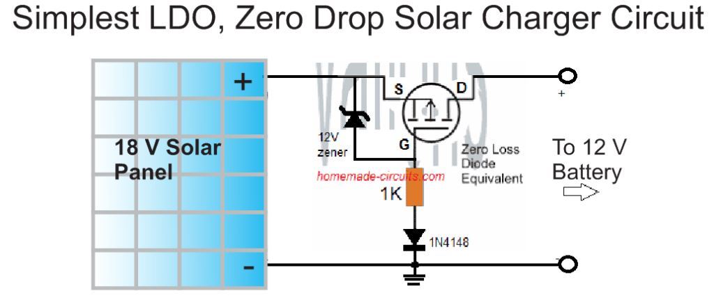
A P channel MOSFET is used as a zero drop LDO switch. The zener diode protects the MOSFET from high solar panel voltages above 20 V. The 1N4148 protects the MOSFET from a reverse solar panel connection.
Thus, this MOSFET LDO becomes fully protected from reverse polarity conditions and also allows the battery to charge without dropping any voltage in the middle.
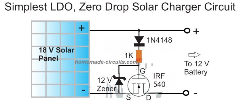
For an N-channel version you can try the following variant.
Using Op Amps
If you are interested to build a zero drop charger with automatic cut off feature, you can apply this using an op amp is wired as a comparator as shown below.
In this design the non-inverting pin of the IC is positioned as the voltage sensor via a voltage divider stage made by R3 and R4.
Referring to the proposed zero drop voltage regulator charger circuit diagram we see a rather straightforward configuration consisting of an opamp and a mosfet as the main active ingredients.
The inverting pin is as usual rigged as the reference input using R2 and the zener diode.
Assuming the battery to be charged is a 12V battery, the junction between R3 and R4 is calculated such that it produces 14.4V at a certain optimal input voltage level which may be the open circuit voltage of the connected panel.
On applying the solar voltage at the shown input terminals, the mosfet initiates with the help of R1 and allows the entire voltage across its drain lead which finally reaches the R3/R4 junction.
The voltage level is instantly sensed here and if in case it's higher than the set 14.4V, switches ON the opamp output to a high potential.
This action instantly switches OFF the mosfet making sure no further voltage is allowed to reach its drain.
However in the process the voltage now tends to fall below the 14.4V mark across the R3/R4 junction which yet again prompts the opamp output to go low and in turn switch ON the mosfet.
The above switching goes on repeating rapidly which results in a constant 14.4V at the output fed to the battery terminals.
The use of the mosfet ensures an almost zero drop output from the solar panel.
D1/C1 are introduced for maintaining and sustaining a constant supply to the IC supply pins.
Unlike shunt type regulators, here the excess voltage from the solar panel is controlled by switching OFF the panel, which ensures zero loading of the solar panel and allows it to operate at its most efficient conditions, quite like an MPPT situation.
The LDO solar charger circuit without microcontroller can be easily upgraded by adding an auto cut off, and an over current limit features.
Circuit Diagram
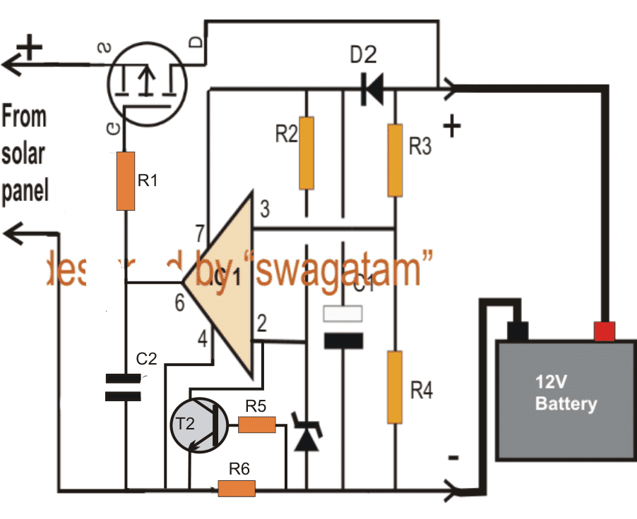
NOTE: PLEASE CONNECT THE PIN#7 OF THE IC DIRECTLY WITH THE (+)TERMINAL OF THE SOLAR PANEL OTHERWISE THE CIRCUIT WILL NOT FUNCTION. USE LM321 IF THE SOLAR PANEL VOLTAGE IS HIGHER THAN 18 V.
Parts List
- R1,R2 = 10K
- R3,R4 = use an online potential divider calculator for fixing the required junction voltage
- D2 = 1N4148
- C1 = 10uF/50V
- C2 = 0.22uF
- Z1 = should be much lower than the selected battery over charge level
- IC1 = 741
- Mosfet = as per the battery AH and the solar voltage.
Using N-Channel MOSFET
The proposed low dropout can be also effectively implemented using an N-channel MOSFET. as indicated below:
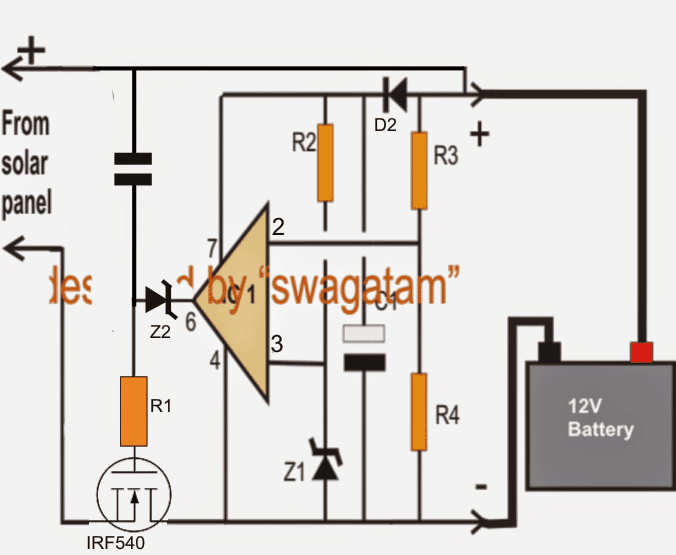
NOTE: PLEASE CONNECT THE PIN#4 OF THE IC DIRECTLY WITH THE (-)TERMINAL OF THE SOLAR PANEL, OTHERWISE THE CIRCUIT WILL CEASE TO WORK. USE LM321 INSTEAD OF 741 IF THE PANEL OUTPUT IS HIGHER THAN 18 V.
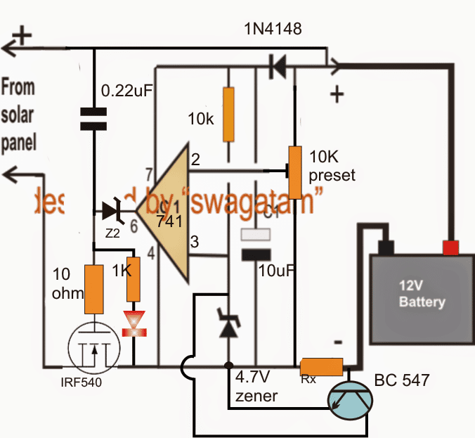
Adding a Current Control Feature
The second diagram above shows how the above the design may be upgraded with a current control feature by simply adding a BC547 transistor stage across the inverting input of the opamp.
R5 can be any low value resistor such as a 100 ohm.
R6 determines the maximum allowable charging current to the battery which may be set by using the formula:
R(Ohms) = 0.6/I, where I is the optimal charging rate (amps) of the connected battery.
Finalized Solar zero drop battery charger circuit:
As per the suggestion of "jrp4d"the above explained designs needed some serious modifications for operating correctly. I have presented the finalized, corrected working designs for the same through the below shown diagrams:
According to "jrp4d":
Hi - I've been messing about with Mosfets (voltage control circuits) and I don't think either circuit will work except where the line in voltage is only a few volts large than the target battery voltage. For anything where the line in is much more than the battery the mosfet will just conduct because the control circuit can't control it.
In both circuits its the same problem, with P-channel the op-amp cant drive the gate high enough to turn it off (as observed by one post) - it just passes the line voltage straight thru to the battery. In the N channel version the op-amp can't drive the gate low enough because its operating at a higher voltage than the -ve line in side.
Both circuits need a driving device operating at the full line in voltage, controlled by the op-amp
The suggestion above looks valid and correct. The simplest way to rectify the above problem is to connect Pin#7 of the opamp IC with the (+) of the solar panel directly. This would instantly solve the issue!
Alternatively the above designs could be modified in the manner shown below for the same:
Using NPN BJT or N-channel mosfet:
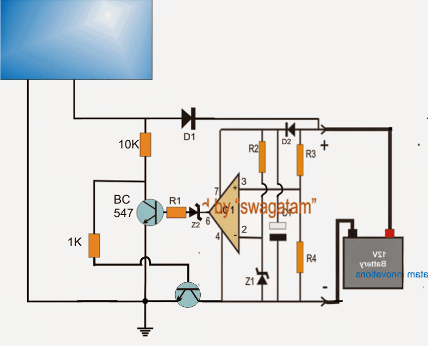
In the above figure the NPN power transistor could be a TIP142, or a IRF540 mosfet .....and please Remove D1 as it's simply not required.
Parts List
- R1, R2 = 10 K
- R3, R4 = use an online potential divider calculator for fixing the required junction voltage
- D2 = 1N4148
- C1 = 10 uF / 50 V
- C2 = 0.22 uF
- Z1 = should be much lower than the selected battery over charge level
- IC1 = IC 741
- Lower Transistor = TIP142 or as per the battery Ah and the solar voltage.
Using PNP transistor or P-mosfet
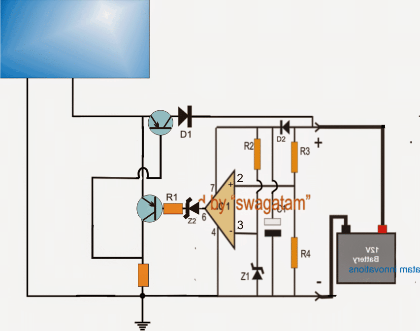
In the above figure, the power transistor could be a TIP147 or a IRF9540 mosfet, the transistor associated with R1 could be a BC557 transistor......and please Remove D1 as it's simply not required.
How to Set up the LDO solar charger circuit
It's very easy.
- Do not connect any supply at the mosfet side.
- Replace the battery with a variable power supply input and adjust it to the charging level of the battery which is supposed to be charged.
- Now carefully adjust the pin2 preset until the LED just shuts off....flick the preset to and fro and check the LED response it should also blink ON/OFF correspondingly, finally adjust the preset to a point where the LeD just shuts off completely....seal the preset.
- Your zero drop solar charger is ready, and set.
You can confirm the above by applying a much higher input voltage at the mosfet side, you'll find the battery side output producing the perfectly regulated voltage level that was previously set by you.




Discussion & Solutions
Thank you Emmanuel, for your kind words, I am always happy to help!
The zener diode is used to block leakage voltage from the opamp output while it is at logic 0V. Because even while it is at logic 0V, it leaks around 1V to 2V, and the zener diode blocks this voltage. The zener value can be a 3V. You can also replace the zener diode with two 1N4148 diodes in series (anode towards pin6).
LM741 is not compulsory at all. you can easily replace it with any other standard opamp or even with a LM393 comparator…just beware of the pinouts which may be different for different ICs.
Thank you sir for always there as a source of knowledge for everyone of us. May God continue to enrich your wisdom sir.
I wish to ask wether Zener diode(Z²) at pin 6 of the ic must be there or not. If must be there, what is the rated voltage of the zener diode.
my second question, at my location, i could not find LM741 ic but i see UA741. what is the alternative ic to LM741 can you recommend please.
Thank you sir.
Diode is not 100% zero drop, but the transistor versions are almost 100% zero drop…
What is the difference?
Yes, better than an ideal diode…
Is this the same as an ideal diode? Do you have an ideal diode topic?
Ok, please remove the 1k from the MOSFET gate…
Thanks sir. 100ah batteries
What is your battery Ah rating? Please remove the gate 1k resistor, and check again…
I made the second to last circuit npn type for a 24v system, it controlled well but when the sun shines for long and it is full, the mosfet gets very hot even with heatsink and fan.
is there anything to do to reduce pressure on the mosfets, I used 10pcs irfp 260 for 150w panels 2 Pcs @ 22.8v
Dan, In that case you can use the previous circuit which I suggested, and connect it between the solar panel and the series battery bank.
Replace the transistor with MJ10022,
Replace the zener diode with a 141V zener diode,
Replace the resistor with a 10k 5 watt resistor.
Yes sir
OK, that means the 10 batteries are also connected in series?
Thanks sir, the panels are connected in series to get 170v, the batteries each is 12v 40ah.
Please tell me how are the 10 batteries connected with the solar panel voltage? And what is the voltage rating of each battery? I will try to solve it.
Thanks, I don’t understand how this circuit will be connected with each battery and the overall 170v solar input.
please kindly guide, sir
You can configure the following regulator circuit with each battery separately.
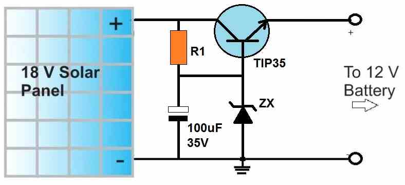
The transistor, R1, and the zener values will depend on the battery specifications.
please how can I reconfigure to do120v input for 10 batteries, with 170 solar input. hope for a favourable response
The mosfet in this circuit will only work when the battery has the lowest internal resistance. Otherwise-overheating and failure.
Mosfet does not have time to give heat to the radiator.
Please replace the MOSFET with a BJT and try again. Let me how it goes.
I try 2nd circuit (Simplest LDO N-MOS) but when solar panel voltage drop below battery voltage, then current flow back to solar panel. I want to replace schottky diode with your circuit. How could I do?
Hi Seun, are you referring to the following circuit?
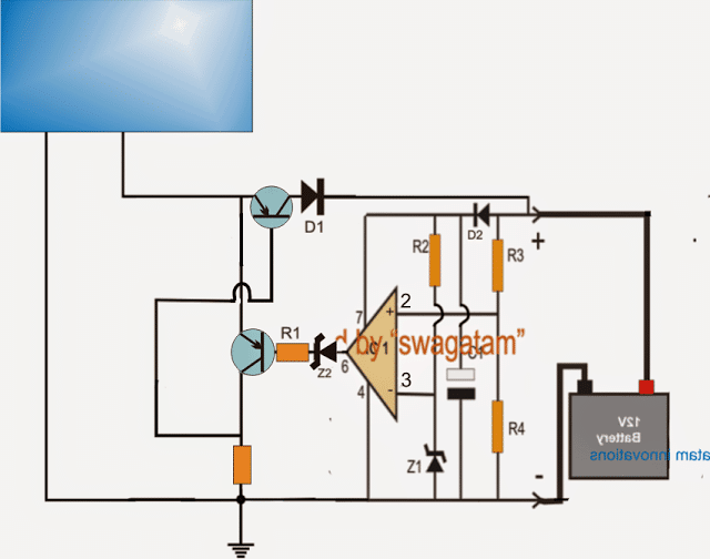
I guess you used the mosfet in place of the upper power transistor.
As you can see that the upper transistor has only the battery as the load. If your mosfet is correctly rated to handle the battery current then it should not heat up much.
You can try using a BJT instead of a mosfet and check the results because BJTs are more reliable and predictable than mosfets.
Try using a TIP36 and makes sure the base resistor (ground resistor) is adjusted correctly for maximum current delivery.
Good day Swag, I designed the second to last circuit for solar controller 3years ago, worked perfectly without fans, but recently I designed same circuit but the mosfets blow without fan. Now I must use fan, please what could be wrong.
For 4 different solar panels, 4 different op amp circuits would be required, a single circuit cannot be used for controlling 4 solar panel systems.
6V can be used but only R3/R4 will need to be changed accordingly.
Using the second to the last circuit here, can one circuit used to drive 4 MOSFETs sets, single for 4 different solar systems, e.g say 1kw solar system for 4 different inverter power systems.
Also, how can I modify it for 6v battery?
Tinu, I did not understand your question…which circuit are you referring to?
Please how can I use one circuit of the n-channel MOSFETs below to control 4 DIFFERENT SOLAR system setups, can it supply adequate voltage to the gate?
Can I modify the circuit for 6V battery, how, Sir?
Thanks
No problem Chris, all the best to you. Let me know if anything goes wrong.
Alright. Mr swag, Thank you so much.
I’d do just that. If I encounter anything else. I’ll be sure to text you.
You can connect them in parallel, just make sure they are mounted on a common single heatsink, very close to each other.
MOSFET source follower will drop around 5V so that may not be very efficient.
Okay.
1. How about in each Solar panel’s circuit, I connect two TIP41c in parallel(just like MOSFETs in parallel). would it help increase the amount of current each circuit would deliver?
Or can I use MOSFETs in the circuits in place of the the transistors?
R1 will need to be experimented to find which value provides the maximum solar panel output current.
TIP41 cannot be used since the 100 Ah battery would require 10 amp current minimum,and each panel would need to deliver 5 amps each….TIP41C cannot handle 5 amps.
Thanks for the response.
1) Please what are the values for R1 and Zx that would give Me the required amount of volts I need for this purpose?
Can I replace TiP35 with TIP41c as this former is not available here, but TIP41C is.
Hi Chris,
Surely you can do that! You can build two of the following circuits and connect their outputs in parallel to feed your controller circuit. Make sure to mount the transistor over a very large heatsink.
Hi Swagatam. It’s Chris ????
I’ve got two solar panels here and both are 150watt panels.
But the problem here is that their voltages don’t match. One has an open circuit voltage of 23.5v(which even rises to 24v most times) the other panel has open circuit voltage of about 21.2v.
Is there a way to connect them both to my solar charge controller so that I can make use of them both to charge my 100Ah solar battery?
Just a suggestion. I was thinking of building your circuit above but with lm324(where I’d make use of two it’s opAmps) for each panel to lower down their their voltages to a common voltage (let’s say 19v or 20v) then connect them in parallel and feed it to the solar charge controller.
Please if you’ve got any other better ideas please help me. Thanks.
Your MPPT should have an internal thermal overload protection which will shut off the charger if the circuit overheats. If overheat protection is not there in your MPPT you can add your own overheat cut off circuit using the following circuit:
Seun, If you want to buy an MPPT then you will have to specify the step control feature to the dealer, he will help you out. Thee should be LED indicators on the MPPT which will tell you about the changeovers.
I discovered that mppt controller also has fan. Sir, if the fan in it stops,what will happen to the mppt.
Please Sir, how can a circuit sense this, and stop the charger.
Thanks Sir, Swag, how will I know Mppt that can handle this stepwise control?
Sure Chris, you can use LM358 or LM324 op amps for your application, instead of 741
Hi swag. Its me again????.
My solar panel’s open circuit voltage is 21.2v, and in your instructions, you said we shouldn’t use ic 741 but rather lm321. Stores here don’t have lm321. So please, what other alternative ic can i use?
Can i use lm324? Or maybe lm358?
No problem Chris, let me know if have any further questions.
Thank you so much Swags.
I really appreciate the quick responses here. When I’m done building this circuit, I’ll let you know.
Actually, an LED connected at the gate of a MOSFET will not illuminate due to the high impedance of the MOSFET gate, so LED cannot be used in series with a MOSFET gate. You can put a zener diode instead as indicated in the diagram. The LED indication can be put between pin6 of the IC and the ground line, if required.
The value of the of the zener can be a 4.7V zener
Okay Swags.
You said in the last two circuits, its mandatory to replace the zener diode with a LED. I actually want to build the 5th circuit in this page, but the 5th circuit has a zener diode, Z2 at pin 6#. Must i replace the zener in the 5th circuit with a LED too..
If yes, please tell me.
If no, Please what’s the value of the zener diode.
Thanks
You are welcome Chris!
1) Yes if you don’t the want the current limiting feature you can remove the BC547 and RX network from the design. The RX can be replaced with a directly link.
2) The shining diode is actually an LED. You can remove that if you don’t want any kind of indication feature in the design.
Thanks Swags for the quick response. Here’s another question.
I intend building the 5th circuit, but for now i don’t need the current control feature.
1) Could i still build the circuit without including the bc547, then ignore Rx and link it directly?
2) There’s this Shining diode connected to a 1K resistor in the 5th circuit beside the IRF540 mosfet. Is it necessary to include it?
*And if yes, what’s the number of the diode?
* if no, can i just remove both the shining diode and its companion(the 1K resistor)????
Thanks.
Hi Chris, The set up procedure is explained for the last two circuits. I am sorry, I forgot to show the positions of the LEDs. Actually in the last two circuits the zener diodes connected at pin#6 of the IC 741 must be replaced with LEDs for the required indications. The polarity of the LEDs will be exactly opposite to the shown polarities of the zener diodes.
2) For the 4rth and 5th circuits using N channel mosfets, the pin#4 can be connected directly to solar negative terminal but nothing needs to be done to the pin#7 because the entire positive line is already associated with the solar panel positive terminal.
Hi Swagatam. I’m kinda new to making circuits.
1) I’m confused on how to setup the circuit. You made mention of using a LED to test the circuit. Where am I going to connect the LED?
2) In your above circuit (after the 5th circuit posted in this page), you made mention that pin 4# should be connected directly to the (-ve) of the solar panel(i.e for the NPN mosfet version). My question Is, should we still connect pin7# directly to the (+ve) of the solar panel as well? Or ignore connecting pin7# directly to +ve of the solar panel but ensure we connect pin4# to the -ve of the panel?
Note: this questions are for the NPN mosfet version.
Thanks.
It will depend on the MPPT specifications. If it is designed to sense and control the 84 amp current in steps, then it can be used.
Sir, can a mppt charge controller intelligently charge the 200ah battery with 84amps?
For controlling 20 amp charging current a single IRFP2907 should be quite enough
Thanks Sir for your reply,
Please which n-channel MOSFETs will you recommend, but even with 12pcs of mosfets, heatsink and fan, the MOSFET got damage.
Hi Seun, applying 84 amps to a 200 Ah lead acid battery will ruin the battery soon. The correct amount of current which could be applied continuously to a 200 Ah battery is 20 amps….which may take more than 10 hours for the battery to get fully charged. On the other hand if a faster charging is required, then the 84 amp may be applied to the battery until it reaches its 60% charge value, and then the current could be reduced to 20 amps, until fully charged
Yes, 14.1 V or 14V continuous charging will not harm a lead acid battery, since its full charge cut-off level is 14.3V. No, once the battery is degraded there’s no way to revive it….the low voltage will not revive the battery condition.
Good day Sir, I noticed some installed Solar panels of about 1.7kw for one 200ah battery, releasing about 84amps to the battery, is it advisable,
Also, what are the advantages and disadvantages of this in the tropical region with high solar irradiance now. Thanks.
OK Sir, thanks. At this damage, is it safe to put it at 14.1v or lesser. If it can salvage the damage.
Hi Seun, according to me supplying 14.5V to a 12V lead acid battery for long hours can be harmful for the battery. Ideally you must have an auto cut off at 14.3V. If you intend to charge the battery continuously without cut off then you can keep the full charge level restricted to 14.1 V.
It seems your battery has degraded a bit and therefore it is unable to deliver its full capacity.
Good day Swag, please I don’t know what happened to my battery bought 2weeks ago.
Initially, with my 900w panels I set to control at 14.5v, and while on load it holds at that for long.
But now on same loads it drops to 14.1v even at peak sunshine. Please what could be wrong?
Th only way to protect the mosfet is by reducing their dissipation by adding more number of mosfets in parallel and by installing them over an appropriately dimensioned heatsink.
Thanks for this circuit, I use it to control about 60amps current from my panels, I used heatsink and fan to prevent the mosfets from getting hot that could lead to damage.
Please how can I safeguard it from sudden failure of the fan, because if the fan stops it damages the mosfets.
Sorry I am not sure how a light sensor can be connected with an MPPT for correcting the issue?
I have a few MPPt circuits posted in this blog, you can find it in the following link.
https://www.homemade-circuits.com/mppt-circuit-using-pic16f88-with-3/
P.S. I expect, that normal MPPT would be to slow to react to shading changes with frequencies of 1/2 Hz or more. So I thought that some lightsensor to measure bright sunlight, partly covered or full covered sky and adjusting to it would be a way.
OK, I understand. Thanks alot.
I am looking into a design which should be imune to rapid changing particular shading.
My idea is to have each cell cut into 40 segments and souldering those in serial. That would make Vmax of about 20 Volt and Imax less than 1 Ampere per 1 cell panel. I expect, that there would be no overheat protection needed for partical shading of a single segment in one of those panels. Panelsize would be around 170×170 mm. Alot of those panels could be in parallel with each a Schottky SMD diode 40V 1,5A in flow to protect from other such panels.
Now I am looking into mppt or other method to charge a lifepo4 battary bank with such an array.
Any ideas?
Hi, Actually, the price is with reference to the high current schottky diodes in the range of 50 to 100 amps. For example a typical 100 amp schottky diode may cost 2 times more than a 100 amp MOSFET such as IRF3205, according to my knowledge.
Hi, Thanks for all the information.
Just for my understanding
Why do you claim at the beginning of this article:
“These circuits can be effectively used in place of expensive Schottky diodes, for getting an equivalent zero drop transfer of solar energy to the load.”
The circuit consists of 3 active components an a resistor. A Schottky diode costs about 0,30€ up to 1,50€ depending on power. I do find the same price range for the MOSFET.
Ideally both the batteries must be charged/discharged at 1/10th value of their Ah rating.
Yes Sir, tubular are better but comparing the safe discharge current of 10A of tubular and 15A for agm from the analogy. Which is better in this regard.
Hi Seun, for all 100Ah batteries except Li-ion or Lipo, the safest charge discharge rate is normally 10 Ah.
2) tubular batteries are better than agm batteries
Good day Swag, please what is best discharge current for 100ah tubular battery.
2. Between 100ah tubular and 150ah agm battery, better?
Thanks Sir
Hello Seun, it is the current output that may be higher or optimum in one of the solar panels compared to the other, which may be causing the difference.
Good day Sir, I bought 2 same wattage and type panels of 2 different brands but one charges faster and better than despite same rating and price.
What factors could be responsible?
Hi Seun, the function of Z2 is to block the leakage voltage from the op amp output from reaching the transistor base. Its value can be 3 V. You can replace it with an LED also for the same purpose. For PNP the current flows from emitter to base, whereas for NPN current flows from base to emitter, that is why the zeners are positioned differently for the two versions.
Good day Swag, please what is the value of z2, it’s function, and why is its direction for pnp and npn different. Thanks
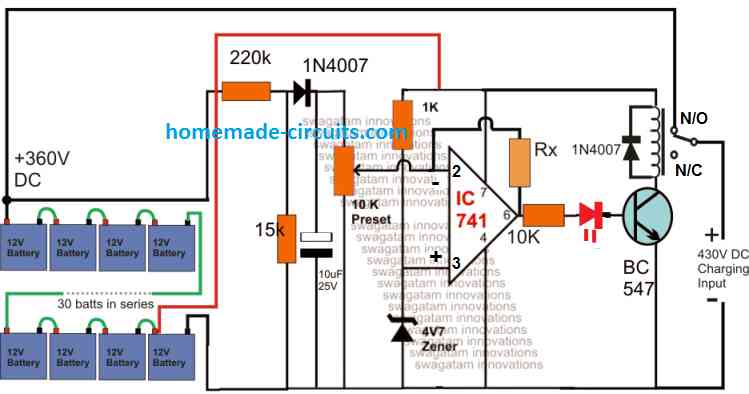
It can be very easily done through an opamp comparator circuit. Clamp pin2 of a 741 opamp with a zener/resistor, and put a preset on pin3 of the opamp. The output pin6 can be configured with a relay driver through a LED at the transistor base. The whole system can be connected to a solar panel.
Maybe high current or voltage sense from solar panel
Should it be a temperature triggered circuit, or a light triggered??
Please Sir, I need a circuit which activate relay when it is sunny but turns off on a cool day.
Thank you for quick answear. Sorry for trouble.
The output will be 18V only, the 12V zener is used only for protecting the FET gate from over voltage
But how first circuit can be considered as zero drop? There is drop from 18V on PV to 12V on zener diod. So there is 5V drop, when PV gives full 18V.
Hi Seun, you can try any of the following circuits:
https://www.homemade-circuits.com/low-dropout-5v-12v-regulator-circuits-using-transistors/
Change the zener to 48 V zener for getting 48V output, or set it as per whatever value you want to get at the output.
Good day Sir, I am trying to design zero ldo controller for 48v system, I tried to connect the 48v solar supply to control circuit of 12v, but couldn’t control it.
So I want to design 48v design, please what are the modifications
Higher values will only help to improve the response!! But it is absolutely not necessary because the improvement is quite minimal….it may slightly help to charge the battery faster
Thanks Sir, for knowledge reason, what’s the effect of value more than 4700uf
Hi Seun, Yes it will have a good effect, the larger the better, in general you can put a 2200uF, or a maximum of 4700uF
Good day Sir, please will capacitor across the battery terminals have any good effect, if yes what value.
OK, then definitely your circuit has problems, because the transistor will block the excess voltage regardless of whether the solar panel voltage is 18V or 22V. You can try replacing the transistor base zener with an LED which will indicate the correct working of the op amp during over voltages above the et value….otherwise your transistor might have gone faulty…
I used the last circuit as a topology for N channel MOSFET
Seun, Please mention which circuit you are referring to, it is not possible to remember the older thread conversation?
Thanks for this article, it is working well. The issue I have is that my panel’s open circuit voltage is 22.5v for 12v system. At peak sunlight, the voltage overshoot the 14.1 set value, but with panel with 18v open circuit, it is well controlled.
Please how can I handle the first panel and the last design
Seun, if their voltage specs are same then you can join them in parallel
Good day sir, well done. I have 5panels 2 150w and 3 100w. Please how can I combine them for my 24v system using the design above, which is not mppt. Thanks
The preset should not be changed once it is set, if you change the preset setting then the cut off level will change and that may not be good for the battery. In winter the current from the panel may drop which may cause slower charging, and the only way to correct this is by adding more panels in parallel, or alternatively you can use a buck converter which will convert excess voltage to current
I used the last circuit as a topology for N channel MOSFET
Seun, which circuit are you referring to??
Thanks so much sir, it is working well with MOSFET. Please how can you help with incorporation of voltage follower, that will help to a automatically adjust instead of using the preset.
I noticed during cool days, the preset needed to be increased which makes it charge faster but needed to readjust the preset not to overcharge the battery.
Thanks sir.
Hi, you can use a suitably rated schottky diode for blocking the reverse battery flow
Hi, can you please help me. I would like a simple circuit that goes between the micro miniature solar strip ( taken from an old not functioning calculator ) and rechargeable batteries ( 1.5 x 4 v ) , so as to avoid current flowing back from the batteries to the solar strip and burning it. They do it on the calculator, so it must be very simple and cheap circuit…… a simple diode will do ? Thanks for helping me out. Cheers. Jack
Seun, that may be surely happening due to the body diode of the MOSFET, otherwise there can be no path for the battery voltage to drain through the solar panel.
Please replace the MOSFET with a BJT and check the response again. You can try a TIP122 for the experimentation.
Thanks sir, I tried the simplest ldo circuit of n channel, I also added LED indicator. But the issues are:
1. The LED is still on at night despite no sun, I observed the positive line is linked between the panel and battery, so I think that may be the cause
2. I don’t know if my n MOSFET has no internal diode, because there is battery drain even when I remove gate voltage supply at night. I have looked into the circuit to know how to circumvent it, no solution. I only disconnect the solar input at night to prevent this occurrence. Please help out
For lightening you must have an earthed rod installed near the panel. And also use industrial based MOV such as below:
https://www.homemade-circuits.com/high-power-industrial-surge-suppressor/
I meant surge from lightning .
Seun, Solar panel will not produce surge, it will produce peak voltage periods during peak sunlight, for that you will need a constant voltage regulator. Please specify your exact load requirement and panel specifications.
OK sir, how can I protect this controller from surge. Thanks
MOVs are not designed for solar panels, it is designed for mains AC applications.
OK sir, thanks. What value of mov can I use to protect the solar system
Seun, it will depend on the wattage of the load, the MOSFET maximum power dissipation rating should be at least 50% of the load wattage
OK sir, thanks. How can I choose a good N-MOSFET with minimal losses.
Use the LDO technique explained in the above article.
Please how can I prevent back flow into solar at night
Yes you can use it.
Sir can i use the circuit uve made using n mosfet 1 diode and 1k and 12vzener diode? Ihave 100ah battery and 150w 19v solar panel is this ok?
Adeyemi, for all systems the gate zener will be 12 V
Please sir, what type of zener diode and resistor can I use for 24v system and 12v system. Thanks sir, Swagatam
The voltage and current specs of the panel must be approximately as per the inverter DC input specs.
How sir, I have 720w panels.
yes you can, as long as the solar panel specs matches the required inverter specs
Please how can I use solar panels and inverter without battery. Thanks Swagatam for your usual assistance.
Thank you! Steve
Hi, No changes would be required in the IRf540 design
Hello – I have a small 6-9 VDC generator charging a 6 VDC lead acid battery C20 capacity: 50 Ah. Maximum charge rate is 15 amps. This is a positive ground system. Would you recommend any changes to the “simplest LDO, zero drop solar charger circuit” above using the low side IRF540 mosfet in a simple charging circuit? Thanks! Steve
Yes the suggested idea will do exactly the same.
Thanks sir, I meant the led will light when sun comes up in the morning and goes off at night when there is no more sun.
You can add an LED in series with a zener diode and resistor. The zener cut off voltage will decide at what solar level the LED is supposed to switch OFF
Hello sir, please how can I add an indicator to show sun is on and off
Thanks Swag.
Hi Allan, it’s actually easy if you understand the basic working of an op amp comparator…you can refer to the following posts for more info:
https://www.homemade-circuits.com/comparators-using-ic-741-ic-311-ic-339/
https://www.homemade-circuits.com/how-to-use-ic-741-as-comparator/
https://www.homemade-circuits.com/how-to-build-simple-electronic/
Hello Sir, can you help me again to use Op-Amp in designing a circuit in making conventional Fire Alarm Circuit Sir? I know that using op amp is the cheapest to be used in making the circuit but i am encountering difficulties in designing th Circuit Sir thanks a lot Sir…
It will restore when the 100K is no longer able to support the latching, when the battery voltage drops to a lower level.
refer to the last diagram from this article for more details:
https://www.homemade-circuits.com/opamp-hysteresis-explained/
“Add a 100K resistor across pin3 to pin6 to latch it OFF once the battery is fully charged.” From your comment up, for the second to last circuit.
If latched how will it reactivate.
which circuit are you referring to?
The MOSFET source is connected with the panel negative, which means during night the supply from the battery will have no effect no the MOSFET conduction. The MOSFET will respond and conduct only to the solar panel voltage, not the battery. The 1N4148 is only for safeguarding the MOSFET gate from reverse polarity.
When the circuit latches at full charged, how will it reactivate charging.
I raised the question because that is the issue I having at night with the circuit. Moreso, the diode in4148 is not in line of the supply, and the source and drain have supply from solar during day and battery at night
The two circuits on top are exactly for this purpose!
Please how can I prevent backflow from battery to solar panels at night, using diode reduces the efficiency. How can it be done that the diode line is activated at night to preserve the efficiency during the day
We have already discussed this, you will need a PWM buck converter which I referred to you earlier…
I need a output voltage of 14.4v to battery at high efficiency of 95% solar conversion. I have tried Lm317 solar regulator which had low efficiency
LM338 is the higher current variant of IC LM317…LM338 is not an LDO, it will control the solar voltage accurately to the battery level. An LDO will pass the entire solar voltage to the battery…what is your requirement??
Ok sir, I have tried lm317 regulator, is 338 efficient like zero ldo
I that case you can use an LM338 based voltage/current regulator.
https://www.homemade-circuits.com/how-to-build-solar-panel-voltage/
I am staying in the tropics with average of 6hours intense sunny day, all things equal, hope this is still safe because 3years ago I connected my panel differently to wet battery, within a month, the battery wet bad.
It is safe since the 18V won’t be constant and will keep getting lower with time…and also if the current is not a lot higher than 1/10th of the battery Ah (lead acid)
As the input voltage from solar is 18.5v, getting to the battery, is it safe for the battery, Sir
Did you check the comparator separately, by connecting it to a normal DC power supply?
see at the end of this video, how LM358 responds to preset turning:
https://www.youtube.com/watch?v=phPVpocgpaI
With the lm358 the output led doesn’t shut off just light on despite varying the preset
You are welcome Nacho!
Yes the MOSfeT is perfect, no problems.
The circuit will be the same for 12V and 24V. The zener and the resistor can be of any minimum wattage. The value of the zener and the resistor will be the same.
Hello,
I must thanks your support which helped charging and discharging 12 V lead acid batteries with different capacity in parallel.
I plan to add current meter, logic switch and Arduino control in the future.
For the N-Channel Ideal Diode (second circuit) I plan to use:
IRFB7437PBF (0,8027 €) -N Channel-
– VDSS: 40V
– RDS(on): typ.1.5mΩ / max.2.0mΩ
– ID (Silicon Limited)250Ac
– ID (Package Limited)195A
For 12 V and 24 V solar panels:
1) Is the circuit the same?
2) Are Zener, Diode and Resistor values the same?
3) Should power values be chosen (Zener, Diode and Resistor) for so high N-Mosfet power?
Best,
Nacho
Tolu, replace 741 with one of the op amps.
Thanks Swag, I got lm358 how can I adapt it for it, having known the inverting, non inverting and the output.
Don’t use the first circuit, use the second last circuit. Replace the op amp output zener with an LED to see the charging status.
Add a 100K resistor across pin3 to pin6 to latch it OFF once the battery is fully charged.
Keep a 1K 1 watt resistor connected across emitter/collector of the lower NPN. This will serve as the float charge voltage supply for the battery.
Remember, while setting up the preset you must keep the 100K latching resistor disconnected, reconnect it once setting up is complete.
For the first circuit where will I put the led bulb to set the battery level.
2. How can I add a float charging feature to it instead of switching on and off.
Thanks
Thank you BB, wish you all the same!!
Sir,
Wish you a healthy and prosperous 2019.
you are welcome 🙂
thank you so much sir..
Hi Allan, you can try the following concept
https://www.homemade-circuits.com/cdi-tester-circuit/
thank you so much Sir, I also have a problem of my Motorcycle’s CDI sir, can also ask your help Sir to come up with a circuit to test the condition of my motorcycles CDI Sir thanks…
Allan, I don’t think that’s possible, because Rf from space could be too weak near the surface of the earth, and may be scattered over a wide area, therefore getting a concentrated amount of RF which could do some useful work looks remote to me.
Sorry Sir, yes sir its radio frequency, i mean those excess radio frequency signal from transmitting antennas sir,..is it possible to harness that sir? thank you sir, i appreciate your immediate response sir..
Hello Allan, did you mean radio waves? I tried to search about radioactive wave but could not find any relevant information, however radio wave certainly is abundantly thrown into the space by the many stars and supernovas and may need a lot of research and investigation to learn about its effective harnessing procedures
Hello Sir, I am thinking about harnessing the excess radioactive frequency in space to be converted into electrical energy but it is too difficult for me to think of a circuit to be used. Can you enlighten me, Sir, if it is possible? I know it is quite a difficult Sir but if it is possible Sir can you help me also Sir in making the circuit Sir THANK YOU SO MUCH…
Hi Rasanga, you can use any of the last two designs for your applications….make sure your panel produces over 15V at 2 amps rate
Hi Mr swargatman.,
I have 50watt solar pannel and 12v/18amp pb- battery.im planing to set up these in a place where sun is shining good 6hours.what changes shuold i do in your circuits.
Hi Andrea, yes you can configure a P channel BJT or mosfet with the positive of the panel and prevent reverse discharging of the battery….
alternatively you can also try a schotky diode for the same
HiSwagatam, Cold I use P-channel mosfet to avoid reverse currant in small panels? I have a very simple circuit with 3v/3w solar panel, a 3.2v lifepo4 3A battery and a stepup 0.9v controller usb. But I'm unable after 7h of full sun to charge the battery more then 30%. Do you have any advice apart how stop reverse current? Thanks in advance for your help. Andrea
Mahesh, I wil reply it here, but for further discussion please post under the same article which we are discussing:
https://www.homemade-circuits.com/2013/04/solar-water-heater-with-battery-charger.html
do not bother about the right side opamp, first make sure the left side opamp operates correctly.
for this apply around 18V input from the solar panel side…then adjust RV1 such that the voltage at the cathode side of D1 becomes 14V…you can connect an LED in series with the base of T1 to ensure that T1 is shunting the excess voltage to ground.
first do this and make sure no matter how much the input is increased , the cathode side of D1 stays at 14V fixed.
this might make T1 very hot…use a large heatsink while doing this.
I will talk about the other parameters once you finish this….
Hi Sir, Thank-you so much for replying,
I made circuit but output 540 burn out after increasing input voltage. but there was wrong wiring connection.
I used Ic lm358 as it is, can I use irf p250n instead of irf 540? I have also connected Ic2 of pin no8 to supply line directly, is it OK? because when input voltage will increase to 100 volt so it may get damaged ics.
There is no voltage on second opamp pin number 7, after turning present of Ic2, and IC1on pin no 5 I am getting 3.5 to 4.5 voltage, currently using 12 and 24 volt DC supply to test circuit, please suggest me what to do?
Hi Mahesh, yes the previous comments are lost due to a change in the site platform, I am sorry about that.
please click on the diagram to get an enlarged view of it and you will be able to see the parts clearly.
the IRF9540 is a P-channel mosfet and TIP147 is a PNP device and both of these will not work….because it needs to be N mosfet and NPN BJT as per the circuit's requirement….so please change them to IRF540 and TIP142
2nos of IC 741 can be used instead of LM358
Hi Sir, Mahesh Lalya here last four days back we talk to you regarding DC voltage control digram for wind wheel generator my generator generates 30 volt @ 4.5 amp normal speed and max may be 100 volt you send me circuit diagram using of solar-water-heater-reg circuit not able to read value of some resistors as flows r7/r6/r9/r10/r11 also can I use opamp as 741 with replacements of LM358 and can I use t1 as IRF9540, & T2 as tip147 and T3 as 840. & D1 as blocking diode,. Or email me on maheshlalya@gmail
Com Z's not able to find that link also because website had changed now. Pls replay soon
Thank you Allan, surely you can use the design for your requirement, however can you please elaborate why you think it's more efficient, because you are yet to test it practically ?? 🙂
just a curiosity, that's all
sorry you cannot replace the opamp by anything else since it's the most efficient and straightforward device than anything other option
hello sir can i adapt your circuit for experimentation sir? i was amazed because it is more efficient as compared to other commercial designs, you're so great sir, instead of an op amp sir what other component can i replace to it?
hello sir,can i adapt your circuit sir for experimentation sir? thanks …
for enabling a reference voltage for the opamp, the value is not critical
why your circuit need to use op amp and zener diode? may I use 3v3 Zener diode?
the max output voltage will show equal to the input voltage from the solar panel
Hi Sir How do I prove there is not voltage drop ?
1) Hi Sir may I use TIP31C transistor?
2) I follow (NPN BJT) construct the circuit only the voltage regulator work only I have no idea.
3) There are extra ground connect below BC547?
4)if the solar panel out greater than 14.4v it will turn off the transistor?
Hi Dwines, It would be difficult for me to judge why the display is not showing the assumed wattage, however the best way to confirm this is by practically checking the voltage and current of each of the panels at a given instant and then comparing it with the display reading, if the display reading shows some other vague reading then it can be considered as incorrect and misleading.
or alternatively you can simply measure the V and I at the junction of the parallel connection and check the actual final wattage delivered at this combined junction for confirming the same…
Hi Swagatam, I want to know your opinion with regards to our solar system. Each panel rated 310W, total of 32 Solar Panels and divided into two groups (16 each) and connected to Growatt 4000. I was wondering, the Power output from the solar produces only around 2289W from the LCD Display. if we total all 32 panels with 310W rating that is around 10KW. How come it did not even reach a 3KW output from the growatt display panel? PV voltage output is 275Vdc (both PV1 & PV2)… Please advise…
Hi Ravipal, I don't think IRF540 is rated at 120V…you may have to go for some other fet rated above this limit…
hi sir,
can i use two or three irf 540 to charge higer voltage and current battries.such as 120 v and 40 amp charging current.thanks
thank you for updating the info, much appreciated.
after testing the Z2 values I found it works with a 12v zener, I also removed D1 so there is zero voltage dropfrom the panel. Ive tested this configuration and works excelent
Thanks for your advise.
I will improve it..
Hi Yasir, In a shunt configuration the relevant parts can be expected to get severely hot, however these must be appropriately rated and suited for the application in terms of current and voltage in order to execute the function correctly…. an SCR may not be the right candidate, a power BJT looks to be a better choice.
the bridge is OK, however it too should be rated at 10 to 20 amp depending on the current for the alternator. For knowing the current you can connect an ammeter in series with the bridge output and check the max current and then dimension the diodes accordingly, and if possible mount them on heatsinks.
Alternatively you can try employing the following circuit and check the results:
https://www.homemade-circuits.com/2013/04/solar-water-heater-with-battery-charger.html
Here T1 will need to be adequately cooled through a heatsink. The "heater" could be a tungsten coil retrieved from a heater coil, or an iron element.
Hi Swag,
Could you please help me?
I have a problem to developed battery rectifier charger in my motorcylce.
The stator produce the voltage too high, 15v up to 100v by three wire. I'm not sure that it is 3 phase.
I had made the rectifier by 6x6A diode full wave bridge configuration and SCR to shunt the current & voltage.
The output voltage is ok is in 12.7vdc, but all parts become hot after 10 second and hotter as long as after.
Please do you have a good formula and circuit to be applied in my motorcycle?
Thank you verymuch, and it will be great if you cc to my email address at denmasyasir@gmail.com
Best Regards,
Yaosir isnan
zero drop charger will only make sure that no voltage is dropped between the solar panel and the load….MPPT is far more advanced…I have already posted a few MPPT circuits in this blog, you can check them out
for 100 watt it will be the same as explained in the last two designs
may i know difference of zero drop solar charger and MPPT
for 100W peak solar panel how to design zero drop solar charger and what is main difference MPPT charger & Zero drop solar charger
In the second last circuit, the 1K from the base of the NPN power transistor can be removed…that's all, nothing needs to be changed beyond this in any of the last two circuits
OK thanks,
In this case, the gate resistor 1K needs to be moved to the second circuit (p-channel)
I will try to implement one of them and let you know.
Regards
for N-channel:
R1=10K
Gate resistor=1K IS NOT NEEDED
Z2=Zener 3.3v, 1/2 W
Z1 Zener connected to pin 2 of IC 741 (previously it was at pin 3)
P-channel mosfet (2nd circuit):
R1=10K
Gate resistor IS NEEDED for safeguarding BC557
Z2=Zener 3.3v, 1/2 W
Z1 Zener connected to pin 3 of IC 741 (previously it was at pin 2)
Collector Resistance of BC557 to ground = 10K
OK, thank you, so let me summarize to avoid confusion
N-channel mosfet (1st circuit):
R1=10K
Gate resistor=1K needed to avoid damage to BC547
Z2=Zener 3.3v, 1/2 W
Z1 Zener connected to pin 2 of IC 741 (previously it was at pin 3)
P-channel mosfet (2nd circuit):
R1=10K
Gate resistor is NOT needed for BC557
Z2=Zener 3.3v, 1/2 W
Z1 Zener connected to pin 3 of IC 741 (previously it was at pin 2)
Collector Resistance of BC557 to ground = 10K
Please confirm, because I am a bit confused with the circuit names, after your reply….
Thank you
for N-mosfet the gate resistor will not be required but for the P-mosfet it will be required, otherwise the BC557 will get damaged…
R1 could be a 10k resistor, for the p-channel version the gate resistor value should be 1k
that's correct no need of the 1K if a N-mosfet is used.
Hello Majumdar
Let me ask some questions:
In these Finalized circuits, I understand Z2 is a zener 3.3V 1/2 W. Correct?
And what is the value of R1 next to the zener?
Also in the p-mosfet version the value of the resistor at the collector of BC557 is 10K. Correct?
And no need for a resistor of 1K at the gate of IRF9540 as in the n-mosfet? Or is not crucial?
Thank you very much!
Hi, thanks for the observations and the suggestions.
I agree with you, I'll try to correct the designs soon….
Hi – I've been messing about with Mosfets (voltage control circuits) and I don't think either circuit will work except where the line in voltage is only a few volts large than the target battery voltage. For anything where the line in is much more than the battery the mosfet will just conduct because the control circuit can't control it.
In both circuits its the same problem, with P-channel the op-amp cant drive the gate high enough to turn it off (as observed by one post) – it just passes the line voltage straight thru to the battery. In the N channel version the op-amp can't drive the gate low enough because its operating at a higher voltage than the -ve line in side.
Both circuits need a driving device operating at the full line in voltage, controlled by the op-amp
It's my pleasure!
a zero drop charger will not drop anything (V or I) between the solar panel and the load, but it's not capable of doing anything beyond this.
MPPT will not drop anything just like the zero drop charger but also make sure that if the load is incompatible with the panel, still it gets the optimal amount of power without loading or distorting the panel output
Thank GOD for your life and you have impacted knowledge into our lives and put food on our table. Now let me ask what is the difference between zero drop charg controller and mppt and their efficiency.
Dear Rickson, thanks for trying this circuit and discussing your problem here.
Could you please try the same using a BJT? I personally do not like mosfets just because of such unpredictable behavior from these devices.
Please try the same with a TIP122 transistor and let me know how it performs, I am sure it won't disappoint you.
If the issue still persists, I'll see if it can be rectified by adding another buffer transistor stage at the output.
Thanks Mark, I might have just missed your comment, saw it just now, sorry for the late reply.
Dear Mr. Swagatam Manjumdar
Thank you very much, I learn lot of thing from your homemade circuit site. I had a wish to assemble a solar charger on my own. Your "Simple zero drop solar charger circuit" made me to assemble it. I did it successfully and made the set up done. The batter charge voltage is 14.5v.
When i connect the variable supply at the solar site for final checking, I shock to monitor the voltage was going more than the set voltage (14.5V) at battery side.
I assembled the IRF540 N channel circuit
Observations
1. The LED shut off at 14.5V
2. IRF540 base voltage is 0 or below 1 volt when Green LED shuts off
3. IRF 540 continuous to supply the input voltage to battery side
4. If i increase the solar side voltage above 14.5v I get the same input voltage at battery side ( if input voltage is 20 out put voltage also 20V – the it is not working as constant voltage out put circuit) I feel as a layman the IRF is not block the voltage at the set voltage point.
I did an addition to check the circuit but that also did not work – the addition is a 1k resistor between S and G of the IRF.
Please help me to complete the project successfully.
Thanks and regards,
Benjamin – rickson.b.a@gmail.com
awesome job Swagatam i was going to try a buck boost circuit but this is more of what i was looking for i might try one down the road, however
Hi Renel
you can use R2 = 10k
Z1 = 6V
R3/R4 calculation will require the input voltage spec, if you can specify the max input voltage I would calculate it for you.
hi sir swagatam,
i have a li-ion battery 12v with 9.8 amp,
can you help me to find the missing value of resistor and z1?
thank you sir…
That's unlikely and cannot happen in the circuits explained above, however a diode may be introduced in series with the battery (+) to avoid discharge through the circuit resistors….
Sir,
Does current flows from drain to source (in nmos) when solar is off? If yes, Why?
Jithin, you can use a 3.3v zener diode, it's not critical…
Sir, How to find the value of Z2 in the modified diagram
Thanking you
it can be a 3V, 1/2 watt zener
for N-ch version, what is Z2 voltage value?
sorry, the above circuit is meant only for regulating the solar panel voltage to the required battery voltage without affecting the solar panel specs….it's not designed to cut off at the thresholds.
Hi,
could you please help to put some LEDs in this circuit to indicate this that battery is charging and one for indicating that it is full?
Belekoy, if the mosfet is switching ON without the gate connected how do you assume it to be OK? A good mosfet will never switch ON without a gate trigger.
Anyway for the time being quit mosfet and try using a PNP BJT such as a TIP127, and check the response
sir, i build this circuit using mosfet IRF9530, problem is output is going as high as 17volts. even i disconnect the gate of mosfet still it is on. i test the mosfet its ok ( switch on when gate goes to 0v and off when gate is +19volts, im wondering what kind of mosfet to use since IRF9540/30 is not functioning correctly with this circuit.
sir, the output of this circuit is not regulating to , 14.4 volts, it goes up to 16.5volts.
sir, I built this circuit but the output does not requlate to 14.4 volts instead it goes up to 16.5 volts, I tried in so many ways to adjust the circuit but I can not simply get the required voltage as explained in your tutorial.
Thanks Pacman,
I think the same circuit which you are presently using for your ARM MCU can be applied for charging your battery also.
Just use a 15V zener and a TIP122 for the transistor in the circuit for the present application, if a 15V zener is not there with you you can put the available zeners in series along with a few 1N4148 diodes for achieving the same.
The concept discussed in the above article is good but the setting procedures could be quite difficult for a novice, that's why I am not recommending the above design to you.
As for D1, it was present in the previous slightly different design which I have modified with the existing one, I'll do the required corrections soon in the parts list, thanks for pointing it out.
Yes 7.5% may be correct but 10% is the recommended value:), so may be you can calculate it as per 10% rate
Hi Swagatam.
The ARM microcontroller is running fine on the solar panel. =)
-So I've now started building this circuit for charging my small 2aH/12V Lead-Acid batteries.
-But I can't seem to find D1. 🙂
D1 is not on any of the schematics. (I'll be using the current-regulated version)
Unfortunately, I don't have the 4.7V zener yet. -But I have a 3.6V, a 3.9V and a 4.3V zener.
Could I adjust the zener using a 1N4148 in series with it ?
BTW: I've read that a 'safe' charging current is 7.5% of the total capacity of the battery.
That would mean for a 2000mAh battery, it would be 2000 / 100 * 7.5 = 150mA.
I've included the formula, so that others can benefit from it.
(My 2000mAh battery says it can handle 500mA charging current, though).
Thanks Pacman, it's my pleasure!!
If 9mA is only that you need then may be just a zener diode with a series resistor would simply do the job….but a zener/resistor config would dissipate some unnecessary energy which could be undesirable….
I have read your other comment will be answering it shortly:-)
Hi Swagatam.
This was exactly what I needed.
I had some idea that it was possible, I just couldn't spot it. 🙂
I have the zener and resistor; and placed an order with the 2N2222 and a SMT version of it in addition.
The ARM microcontroller (NXP LPC1114) only uses around 9mA, when constantly busy at full speed.
So it looks like there will be plenty of current left over, even after the RF-chip have been consuming its part. 😉
You're absolutely a genious and a great teacher!
I learn a lot from looking at your circuits and trying to follow them.
I hope that I can return the favour one day. =)
(I hope I didn't post this twice; my previous attempt was lost; it seems it's a good idea to copy to the clipboard just before pressing "Publish").
..for the TIP122, you can use a 2N2222 or an 8050
Thanks Pacman,
Your problem can be simply solved by using the following circuit, the above circuit is way too complex considering the small voltage level you intend to control.
https://www.homemade-circuits.com/2012/08/simplest-dc-cell-phone-charger-circuit.html
Use a 10k resistor instead of the shown 220 ohms, and use a 3.3V zener in place of the existing zener value.
The output of the circuit then could be directly integrated with your ARM MCU.
I am sure this will work better and be much easier for you to implement.
Hi Swagatam.
This looks like a pretty good circuit.
Thank you both for providing the circuit and answering all those questions.
I've learned a lot from what might sound like silly questions (but I think they aren't).
I'd like to interface an ARM microcontroller to my solar panel.
The microcontroller's job would be to measure the voltage using a resistor voltage divider connected to an ADC pin.
As the ARM microcontroller runs at voltages below 3.3V, I need to regulate the voltage, but I do not want to use a 7812 and a 7805, because they'd use a lot of power.
This is why I started to search for better regulators.
I believe that I could use this as a regulator (and a similar circuit for charging a battery).
My ARM device would then transmit the voltage whenever it changes (max. once per second) via a wireless connection, so a receiving chip would store the results for graphical display.
I could also measure the charge currents.
Without load, my 5W panel gives max. 22.4V; it's intended to be used for charging a 12V battery.
I'd like to ask how low the regulator circuit can go, because I do not yet have all the components required to create the circuit (still waiting for the LM741 / UA741).
Would any Mosfet do; eg. the IRF9530 or IRF9540, for a low voltage like 3.3V ?
(I have a TSM2307 P-channel Mosfet as well, which I would prefer if possible: VDS = -30V max, VGS = +/- 20V max, ID = -3A max, RDS(on) = max. 80…140 mOhm).
As you write… "should be lower than the selected battery over charge level", I believe that the zener can be anything above my microcontroller's minimum voltage level (for instance 1.8V, as the microcontroller's voltage range is 1.8V to 3.6V) ?
you can try IC 301, 318, 709, CA3130, 3140, LF355/356/357, TL071/081 etc
Hi
Can you please give me some alternatives for IC1 741?
Thanks
hello vb,
no changes would be required, you can use the same circuit.
Hello Sir,
Can I use this circuit for 6V/4.5AH Battery. What will be the changes required? Secondly, can I apply say 9V DC at the input in case no solar power available? Thanks.
The above circuit will work for both the inputs.
use an appropriate preset for R4 for getting the desired output voltage
I need these with input of 20v to 40v with an output of 17.5v @ 40amps. Even if a few are in parallel its okay.
Efficiency should be greater than 90%
Kumar
srestimarketing@gmail.com
hi sir
dc input is mppt
use dc in trafo is ok?
Bhanu, yes any P-channel mosfet will work here.
when excess current flows, the base resistor of BC547 develops a triggering voltage for the BC547 which pulls pin2 of the IC to ground, which in turn instantly makes the output of the IC high deactivating the mosfet and switching it off at that instant, the cycle continues keeping the current within the required limit.
Aureliano, the above charger does not include a cut-off circuit, so indicators cannot be used here.
you can use an ammeter and put it in series with the battery positive, when it becomes zero would indicate a full battery
for solar panel working indication you can put an LED across pin6 and ground of the IC via a 10k resistor.
Thank you Sir me bhanu…..
actually TIP 127 is not available but can i use IRF9530 or IRF9540 as i am using 12v 1.3Ah battery for charging…
Sir one more problem i am facing i know you have told that the BC547 is used here for current control, I just cant' understand how it functions…please sir help me….
I am not getting a clear description from the note…
Sir can i use R3 as 10k and R4 as 10 preset as according to comments posted by u…
Thank you sir…..
bhanu, an n channel cannot be used in the above design, it'll require many changes for that
mosfet is not compulsory here, you can use a BJT such as a TIP127 in place of the mosfet
sir swagatam good day
is it possible to add leds to identify solar panel working and to identify the charging status? where shall i put it? thanks again
sir me bhanu actually my problem is I am using here a N-channel mosfet that is IRFZ44N can it be used here…Thank you sir plz help me sir in this….
it's a standard rule.
Hi Swaga
How?formular calcula
for a 12V batery the output voltage from the circuit should be set at 14.4v
Hi khang,
disconnect pin7 of the IC from the shown position and provide the supply directly from the 20V input but through a 7812 IC and check the response.
HI Sir
I built your circuit design. circuit is limited by the charging line. I choose z1 = 6V, R3 = 3.9k R4 = 10k but the charge under 1A . DC in 10A 20V, 100AH battery.
Can you guide me
Thanks
Hi khang,
here negative refers to zero volt.
Hi Sir
that is 741 use comparator circuit.741 use dual volte(+vcc and -vcc).you connect pin 4 in 0v .it cant's produce negative voltage.
Hi khang, the 741 will produce negative voltage….. please go through the circuit explanation.
Hi Swag
sorry, formular wrong . but i think circuits not work because mosfet p channel work in negative voltage.pin 4( ic 741) connection 0V(mass) . mosfet cant's work . currents charger very low.I 'm check in actual
Thank's
Hi Khang,
I have not yet confirmed this formula so canot say about it.
In the above diagram Z1 and R3/R4 form a valid overcut configuration
hi Swag
pin 3(ic 741) calcular:Vbb=((R3+R4)*Vcc)/R3*R4 is valid over charger
is Z1 valid begin charger
Thanks Vladimir,
I have understood MPPT better than anybody else that's why I am trying to prove that it does not have to be all that complex…..and can be implemented by simpler means, although that would come with a few compromises and limitations which are no big deal.
Please read my other articles about MPPT, you will get an idea regarding my knowledge about it.
If you have personal queries about MPPT feel free to ask them here.
Swagatam, good circuit. It seems that you don1t know what mppt cgarging really is. This charger defenently isn`t. For mppt ypu need an inductor and electronics which wont allow PV module voltage to drop below 17.5v +_ 0.5.
Dear <anish,
You will need a 15amp solar panel for charging a 100AH battery.
You can use IRf9540 mosfet
zener can be 6V, 1/2 watt
R3 = 4.7k
R4 = 20k
Dear Swagatam Sir,
I have a 150 w solar panel with VoC = 21 V and IoC = 6.7 A ,
I need to charge 12 v – 100 AH battery
can you help me in determining values of R3 , R4 , Zener Diode No , Mosfet No . & R6 .
I can procure them along with the Other material and start this project .
best regards.
MANISH
Dear Swagatam Sir,
I have 150 w Panel with VoC : 21 V and IoC :6.5 in peak conditions and Battery to be charged is 12 V , 100 AH .
Can you help me in determining values of R3, R4 , Zener Diode No. , and MOSFET No. so that I can procure them .
Best Regards.
MANISH VISHWAKARMA
Hyderabad
Hi Kassim,
You can try swapping the pin2/3 with each other for an nmos at the output.
Hi Swag,
pls i would want to use an nmos instead of pmos in the circuit . How could tha be done ?
Tmx.
yes you can use the above circuit for that purpose.
If its voltage and current ratings are as per your battery charging rate then it is OK.
The zener can be a 6V zener,
10k for R3, and 10K preset for R4. Adjust R4 until you get exactly 15V at the output.
Z1 can be a 4.7V zener, current limit can be easily included by adding a transistor stage, will try to update it soon.
as expressed in the above comment, inclusion or elimination of resistor does not produce any affect in mosfet gate triggering.
A mosfet requires a voltage across its gate and source in order to conduct, positive for N-channel and negative for P-channel
here the P-channel acquires a negative potential via the shown resistor for conducting. It can be replaced with a short still the mosfet would work but the positive from the opamp would get shorted to ground getting damaged, that's why the resistor is included specifically.
When the opamp output goes high it generates a positive potential at the gate and cuts off the negative drive such that the mosfet shuts off and process continues as explained in the article.
You can refer any online source for knowing how mosfets work in details.
It's mosfet gate drive resistor
it's for enabling the mosfet to start conducting, without it the circuit will never initiate when switched ON.
p-channel
you can use a BJT (transistor) in place of mosfet, relay will not work.
good day! presently solar panels will be costly no matter from where you buy it.
I have no idea regarding exact shops who are specialized in the PV field.
You can try ordering it online from any chinese vendor as they are quite competitive.
Hi Rashid,
Use an online voltage divider calculator for determining the values of R3/R4 such that it's junction gives 14.4V at 15V input.
Set it with a ac/dc power supply in place of the solar panel, means after this anything above 15V will be appropriately controlled as explained in the article.
i m tapas
where i will found solar plates…
Hi Sir,
I have a 12V, 130AH battery and a solar panel of 24V 150W.
How do I calculate R3 and R4 ?? Also please help for the value
of Z1 and mosfet ratings.
Thank you in advance.
Rashid