In this article I have explained a simple low battery indicator circuit using the IC 555 and a few resistors only.
Circuit Concept
Many electronic circuits such as emergency lights, battery chargers, UPS systems, flashlights etc essentially require a low battery indication feature in order to avoid over discharge of the involved battery. An over discharge could mean a permanent damage to the battery.
A novel little low battery indicator circuit can be learned here, which incorporates just a single IC555 and a few resistors, it's a simple "plug and watch" kind of circuit.
Audio/Video Representation
Circuit Operation
The circuit functioning may be understood with the following points:
We all know regarding the basic characteristic of the IC 555 when it's being used in the comparator mode: if pin#2 is subjected to a potential lower than 1/3rd of the Vcc, the output pin#3 goes high.
The above fact also indicates that pin#2 responds with reference to the supply voltage applied at pin#8 of the IC, which implies this voltage at pin#8 should be clamped to some constant level.
Therefore in the proposed design the supply pin of the IC is fixed at some reference level using a zener diode.
The battery voltage is allowed to reach pin#2 of the IC via the preset, which must be manually set such that voltage at pin#2 just falls below the 1/3rd of the zener voltage when the battery voltage reaches the specified lower threshold.
The above setting can be done manually by applying a sample voltage to the circuit imitating the lower threshold level.
Suppose, the specified lower threshold is 11.4V for a 12V battery, the applied sample voltage can be fixed at 11.4V and applied to the circuit.
Next, the preset should be adjusted such that the LED just lights up. Now the preset may be glued by some permanent adhesive for preventing the setting from getting disturbed.
The set circuit is now ready to be attached with the battery in question, whenever the battery voltage reaches the 11.4V mark, the LED would light up, providing the required low battery information.
Simple low battery indicator circuit using IC 555 Diagram is shown below:
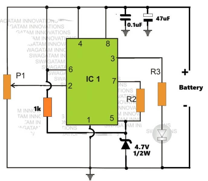
Parts List
R1,R3 = 10K
R2 = 100K
IC1 = 555
P1 = 100K preset
Z1 = zener diode, having voltage lower than the battery voltage.
IC 555 Pinout

555 Low Battery Indicator with Flasher
This 555 low voltage indicator circuit is designed to activate an LED when the power supply voltage exceeds a specific threshold and to make it flash when the batteries require replacement.
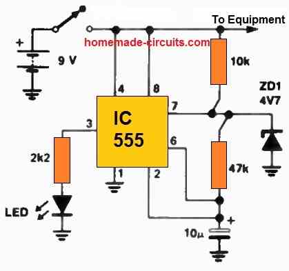
The provided component values are optimized for a 9 V operation. The flashing function initiates at approximately 7.5 V, while the LED won't illuminate at all below 2 V.
The circuit comprises a 555 timer configured in the bistable mode, serving as the driving mechanism for the LED.
The key element here involves connecting a zener diode between pin 7 of the 555 timer and the ground.
During standard operation, pin 7 oscillates between one-third and two-thirds of the supply rail voltage (Vcc). If the voltage at 2/3 Vcc exceeds the zener voltage, it inhibits the 555 timer's functionality.
To adapt this circuit to your specific needs, determine the minimum voltage necessary for proper equipment operation and multiply it by 2/3 to obtain the required zener voltage.
Additionally, you may need to adjust the resistor (R) to match the particular LED you intend to use.
In its original configuration, this indicator circuit drew 7 mA of current at 9 V, decreasing to 5 mA at 7 V.
If these values are potentially problematic for your application, consider using the CMOS variant of the 555 timer, the 7555.


Comments
The first circuit ‘Simple low battery indicator’ is very poor.
a – pin6 at a higher voltage than Vcc will burn out the 555. I caught it when heating up thankfully.
b – it’s very imprecise; Vcc to the chip will change when the LED is lit as the zener is not an ‘ideal’ voltage regulator
c – there is no decoupling (e.g. capacitor on 555 pin 8 to ground) and so oscillation is possible.
Apologies for being negative. On a more constructive note, try using the zener (and resistor to Vcc) to clamp pin 5 (control) and use this as a reference voltage. This worked well for me.
Joe
Hey thanks, You are right, I probably designed it in a hurry, it was a long time ago.
I have corrected the circuit accordingly and have updated it above.
Hi Swagatam,
thanks for your prompt reply and correcting the schematic. Thanks also for your very helpful website.
Joe
You are welcome Joe, I appreciate your kind words, and thanks for your helpful feedbacks…
hello SIR
12 v battery charging auto cut off using ic 555 is possible
Hello Khemraj, there’s one related circuit at the end of the following article, you can check it out:
https://www.homemade-circuits.com/high-current-10-to-20-amp-automatic/
Why we use battery in current detector circuit using 555ic…..without battery we can do that project or not….
Anybody actually built this circuit?
Firstly I burnt out several chips because pin 6 and 2 are allowed higher than the supply pin 8.
After that was corrected the LED just comes on or goes off according to where the preset is set, doesn’t matter what the input voltage is.
It is based on the following day/night switch circuit which is a tested design, you can modify your design accordingly
https://www.homemade-circuits.com/wp-content/uploads/2012/01/lightactivatedswitchcircuit.png
hello Sir swagatam.
will the LED of this circuit blink?,or it will just flash continually.
Hi Joseph, the LED will be constant, it will not blink
Hello, I am hoping to use this circuit to sense if a sensor output has degraded down to an unacceptable level. The sensor is an electrochemical oxygen sensor that initially outputs 0V at 0% oxygen, and 2.09V in air at 20.9% oxygen. I would like to be able to tell when the sensor can no longer generate 1.25V in air. I have 5V power available for the 555 timer (NE555P) and am hoping I can use the 5V to supply the chip with power, and then step the 5V down to 1.25V using a voltage divider, and apply it at the CONT pin. The sensor’s output would then be applied to TRIG and if the sensor can no longer generate 1.25V in air, then an LED is lit from the OUT pin. my questions are: can I use a voltage divider to step 5V down to 1.25V for setting the CONT pin? Why, in your circuit is there a resistor (R2) between CONT and DISCH? Also, why is THRESH connected to battery(+)? Thank you for posting your designs, Swag! This foray into ICs is my first.
Hello Travis, the above design was primarily intended to be used like a darkness activated switch, and is basically configured like a comparator. So the actual attributes of the IC 555 have not been used in this design, that is why pin#6 is disabled by connecting it to the positive line.
Pin#7/5 are joined with a R2 to introduce some hysteresis into the circuit, so that the output does not oscillate during the thresholds.
I personally wouldn’t recommend this design, instead you could try the following ones which can be more efficient with the task:
https://www.homemade-circuits.com/how-to-make-simple-low-battery-voltage/
https://www.homemade-circuits.com/low-battery-indicator-circuit-using-two/
Thank you Swag! I have taken your advice and modeled a new circuit after the IC741 design. Since my application is low power I have substituted LM741 with a Rail-to-rail IC [MCP6241] which accepts +5V. I could not find a Zener at a suitable voltage, and the power supply is regulated, and my application does not require high precision, so I am using a voltage divider to set the threshold (I may use a trim potentiometer until I find the right threshold though). The datasheets for these ICs state that a bypass capacitor is needed between the power rails; is a bypass capacitor necessary for these slow on/off applications? or are they only needed when the circuit is operating at a higher frequency? Again, thank you for developing and posting these designs and for providing useful feedback. =)
You are welcome Travis, all your considerations look OK to me, and will help to provide you the optimum results.
The bypass capacitor also referred to as decoupling capacitor can be used regardless of the circuit specifications, because it is a good practice to have it across the supply rails for every IC, so you may include it.
hello sir
i am simulating the circuit in proteus environment
but it is not giving any output
hello Reader, don't depend on simulators, instead build it practically, you will be able to get the results immediately, provided you connect everything correctly.
It's pointless to use 12V zener with as 12V battery?
if your IC is getting hot with a 12V battery that means either your IC is faulty or you have done something seriously wrongly in the circuit.
alternatively you can try the first circuit from this article
https://www.homemade-circuits.com/2011/12/how-to-make-simple-low-battery-voltage.html
Hi Swagatam Majumdar,
I really like your projects, but can you make a 24v low battery alarm, that will activate at 22V?
Kind regards,
Viktor
thank you beic,
you can use the following circuit for your 24V application:
https://www.homemade-circuits.com/2013/05/low-battery-indicator-circuit-using-two.html
the LED can be replaced with any standard 24V piezo buzzer for the alarm sound
hello sir,
what changes have to be made for using it for 3.7v li-ion battery. say at 3.0v the led glows up.
Hello Gaurav, the above circuit will not work with 3.7V, you can try the following circuit instead, for the intended results:
https://www.homemade-circuits.com/2013/05/low-battery-indicator-circuit-using-two.html
hello sir,
what changes have to be made if i want to uae this for 3.7v li-ion battery.
say at 3.0v the led should glow.
Thank you dear Ankit,
I think an opamp circuit would be more appropriate and easy instead of a IC 555 for the low voltage detection.
You can incorporate the first circuit from the following article, and use the relay set up as given in the second diagram.
https://www.homemade-circuits.com/2011/12/how-to-make-simple-low-battery-voltage.html
you will need to the adjust the 10k preset such that the LED lights up whenever the voltage goes below the intended threshold…for this setting you will need to supply a precise 12V from the battery side of the circuit and adjust the 10k perset to make the LED just light up.
the relay N/C can be then terminated to the 7812 and the subsequent stages.
Dear Sir
your circuits are very useful and also simple enough for DIY hobbyists. Can you please help me with the following
I have installed LEDs and CCFL angel halos in my car as DRLs. These are made to function at 12v and very sensitive. But in car the voltage drops to very low (about 10v) during starting the car and then increases to 14.2v after starting when the alternator functions. This make the leds and ccfl prone to damage.
I will tackle the high voltage with a constant voltage circuit like LM7812, but I need your help for the following. I want to design a circuit using IC555 which cuts off the supply to leds as soon as voltage drops below 12v. (using a relay that gets activated when voltage is below 12v and gets deactivated when voltage increases to 12v again.
Kindly advise. Thanks…Dr Ankit
what part?
Can i replace the zener with another electronic part.
sir i want to use this circuit for DC 12v battery as a low battery indicator. at what voltage it will light up the LED to show the low voltage?
Bilal, keep P1 viper towards the positive supply…connect a 11v supply to the circuit, and adjust P1 until the LED just lights….hopefully this will set up the circuit to respond for a 12V battery whenever it reaches at 11V.
No sir.. capacitor is not needed to power the LED bank.. The capacitor is required only to give the control signal for the flashing circuit.. LED bank should have to be operated using battery power.. The capacitor voltage here acts only as the power source for the control circuits for 5s… When Main power fails.. all the associated control circuits will be powered using the decaying voltage persisting in the higher value capacitor. These circuits will give the necessary control control signals for the intended operations ( say flashing control and Audio Sensor Control ) and these signals are then suitably fed to a transistor driver stage and then it will respond according to these signals on the BATTERY VOLTAGE applied to it which will reflect in the LED bank ( just like when a PNP transistor whose emitter terminal connected to the BATTERY VOLTAGE switches off the LED bank connected between the GROUND and its COLLECTOR terminal when a positive Control signal is applied across its base and ground ) Due to this , all the circuits will stop working after 5 S ( or determined by the Capacitors discharge time ) and thereby saving the battery power to maximum… Battery power will be utilized only when a Manual clap signal is fed.
i am in the middle of constructing a one like that… Will inform you soon about the result.. meanwhile i am also expecting improvements and suggestions from your side too.
sure MIL! we'll wait for it.
thank u very much sir.. i will inform you about the result after making the idea practicalthank u very much sir.. i will inform you about the result after making the idea practical
Yes that's possible!
Sir suppose the current has gone.. Now the entire circuit ( say for illuminating the LED bank 5 times, the timer circuit if any for providing 7s ON time for this LED flashing circuit AND the Clap Sound detecting circuit ) should have to be operated under 3.7 V battery voltage.. Now i am thinking about a large value capacitor ( say 1000 uf or more Capacitance ) which can be used as a power source for these circuits for just 5 S after power failure occurs… My idea is to charge the capacitor at the maximum voltage which can be provided by a DC Voltage source during Mains Power is available ( say a 230 V to 5 V DC converter ) and use the terminals of this capacitor for enabling the above said circuits for just 5 S only after power failure… In any manner, all these circuits should have to be turned off automatically after this 5 s to protect the battery voltage from unnecessary draining. So what is your remark about this IDea ? Can this be done in practical ?
Hi MIL, capacitors cannot be used for powering the LED bank for 5seconds, you might need a 50,000uF capacitor for this
K Sir. Thank you.. I am expecting a good remedy from you soon
Sir while giving the circuit ideas for the requirements i had put forward in my previous comment, you should make 100 % sure that those circuits will be able to work on that much low level of battery voltage ( say 3.8 to 2.8 V range )
I'll see if that's possible or not….
Thank u for the immediate response Sir..
Now i want to think in a different way.. I need a circuit which should operate in the following manner :
(1). When power failure occurs, an LED bank should alternatively switches ON and OFF using a battery backup .. On time of the LED bank should be 1 s while OFF time should be negligible so that we can't feel the OFF time to be too high… This action should have to be done 5 times automatically so that the total time of working of the LED bank shouldn't go beyond 7 s. When the LED bank completes its 5th Illumination it should automatically switched off…
(2). But there should be an option to continue the illumination of the LED bank if any signal is given before the 5th illumination ceases.. That signal should have to be in the form of a Sound Level sensed by a tiny microphone ( used in Mobile Phones )… This means when someone makes a sound ( say Clapping Sound ) before the LED bank illumination ceases at its 5th turn, the LED bank should continue to illuminate even after 5th turn until either its battery voltage falls below its critical low voltage level or Mains power returns..
(3). Can you provide a simplest circuit OTHER THAN the TIMER CIRCUITS to make the 5 times illuminating effect ?
(4). Whatever circuit you are using for creating the illuminating effect, they shouldn't draw any current after their function is accomplished ( say after 5th Illumination or When Clap Signal detected ).. How can this be made into practical ?
My intention is to make a Fully automatic emergency light suitable for working only during night… The requirement given at first is to make sure that no unnecessary power wastage from the battery is occurred due to the unwanted operating condition of the Emergency lamp ( suppose when Main power fails during midnight. We will be sleeping during that time.. So no need of the Emergency Lamp.. )
Therefore no one is there to give a sound signal to the microphone during that time and therefore the LED bank automatically switches off after the 5th Illumination… Even though this method fails when lightning and external noise come into act.. but i am not considering these factors right now..
SO I AM EXPECTING A SATISFACTORY REPLAY FROM YOUR SIDE AS EARLIER AS POSSIBLE.. and remember to use least amount of components and the components selected should have to be simple ones too..
thanks
I'll try to design if possible, and post it in my blog soon…
Sir the higher voltage cut-off circuit using transistors are not working properly because they are not providing a sudden change in output dc level, instead the output of this configuration gradually changes which will not be sufficient to create an abrupt Higher voltage cut-off condition…plz provide me a better circuit to facilitate these requirements, but using least no. of components.. the circuit using IC555 is more accepted.. In the previous comment Music iz life asked you to provide a circuit of HIGHER VOLTAGE CUT-OFF using 555 IC, but you have provided him with the circuit of a Lower Voltage Cut-off
MIL, you can try the second circuit from the following link, it will provide you the required snap ON and snap OFF kind of switching in response to the over and under battery thresholds:
https://www.homemade-circuits.com/2011/12/how-to-make-simple-low-battery-voltage.html
Sir, Can you provide an effective way to build an Over voltage indicator circuit using IC 555 ?
I want to concatenate the Lower Voltage Indicator as well as Over Voltage indicator together on a single 555 IC… IS it possible so ? If your answer is Yes… How ? Plz explain Sir with diagrams…
Hi Music iz life,
Presently I do not have this circuit with both the indications, although I have a low voltage indicator using IC 555 which you can find here:
https://www.homemade-circuits.com/2013/05/simple-low-battery-indicator-circuit.html
Hello Sir,
The simplicity of circuitry & explanation given is great!!!. I wanted similar circuitry for indicating Reserve & Low Lead acid battery charge at 30% & 20% of total charge respectively. Please guide me. Thank you.
Thanks Rohit, you can try the following circuit, it has two extra indication steps that you can use for a better monitoring:
https://www.homemade-circuits.com/2013/06/3-step-dc-voltage-level-monitor.html
Sir I want a circuit in which a relay should be triggered wen batt voltage goes above certain voltage or falls below certain voltage.
aditya, you can try the second circuit from this article:
https://www.homemade-circuits.com/2011/12/how-to-make-simple-low-battery-voltage.html
what modification is required in circuit to connect to a 48V DC supply.
Use R1 = 10K, 1 watt
use one 22k resistor in series with the 100k on its upper lead.
use a 12V zener.
connect 44V and adjust the 100k preset until the LED just lights up