In this post I have explained how to correctly connect an IR photodiode in circuits such as a proximity sensor circuit. The explanation is presented in the form a discussion between one of the dedicated readers of this blog NVD, and me.
Here's the discussion which explains how to connect a photodiode in an electronic circuit.
Verifying IR Photodiode Connection in a Circuit
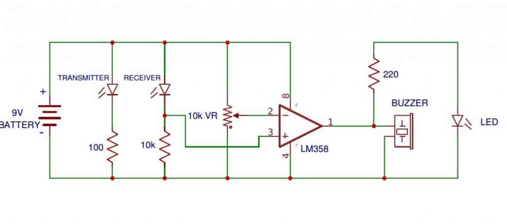
Question: Can you please tell me whether following circuit work or not. I think output of ic is 5v. I want the output to be connected to a 12v relay instead of buzzer..can you tell what alterations should i make in the circuit..
Analyzing the Circuit
Answer:
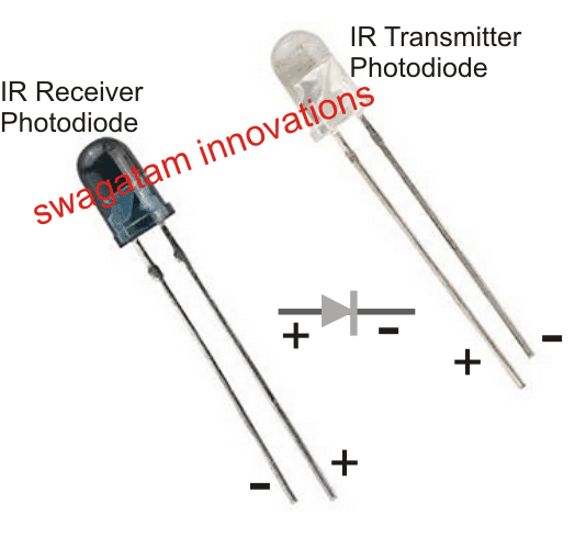
(+) is the Anode, and (-) is the Cathode of the Photodiode. In other words the pin associated with the wider plate inside the photodiode will be be the Cathode, and the pin associated with the thinner plate inside the photodiode will be the Anode
- if it's set correctly then it should work..However the diagram above has many mistakes and will never work. The IR photodiode configuration with the opamp will need some modifications.
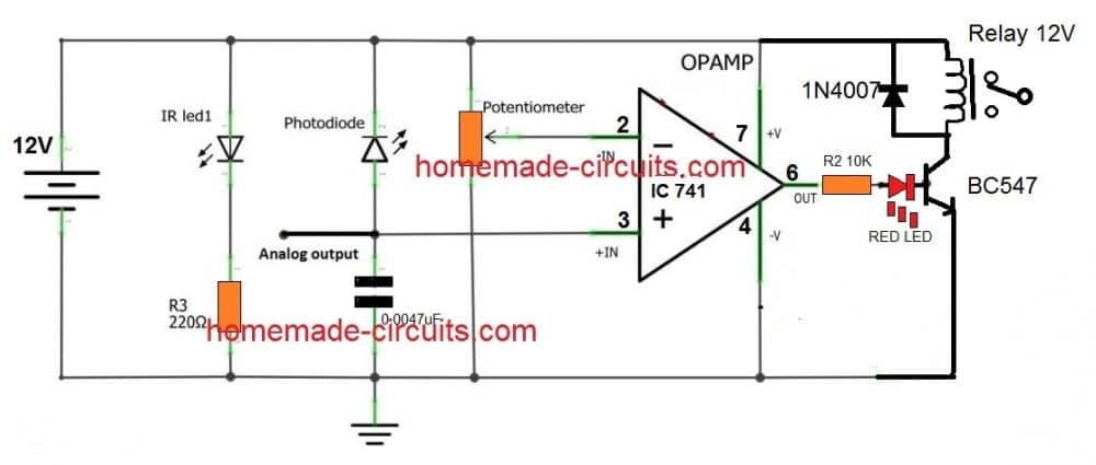
- For configuring a relay, you can use a BC547/relay stage at the output of the opamp, the base resistor cold be 10K
- For a details information regarding the relay driver stage you can refer to the following article: https://www.homemade-circuits.com/2012/01/how-to-make-relay-driver-stage-in.html
Question:
ok is there any positive and negative terminal for IR receiver and transmitter like led. I'm new to to this, that's why asking
Polarity for IR Photodiodes in Transmitters
- just like any other diode, IR photo-diodes also have polarity and must be connected accordingly.
Question:
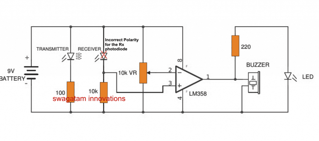
In the circuit, photodiode is connected forward bias. is it wrong? Please check sir.
Circuit Diagram
IR Photo Polarity for Receiver
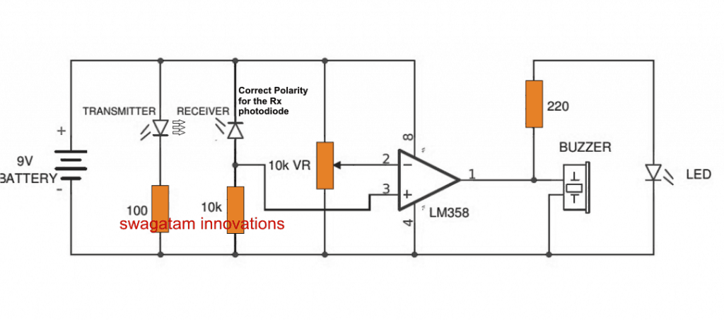
- The transmitter IR photodiode polarity is correct...receiver polarity is wrong, needs to be inverted for the receiver as shown below.
Question:
sir, firstly i forgot to connect IC pin 3 to receiver resistor then i have given a supply of 12V therefore Led lights up only. After that I connected pin 3 to resistor and given 9V. Now led lights when i turn the variable resister to one side. LED doesn't light up when obstacle is brought in front.
Can an IR Photodiode get Burnt
I connected everything properly still it doesn't work, is there a chance of IC or photodiode getting burnt when i connect to a 12V supply. Do you have any circuit diagram for IR proximity sensor.
Please help me sir.
Answer
- The photodiode will never burn as long as its connected in series with a resistor.
So why is the Receiver Photodiode not Responding
Answer:
In the diagram above the photodiode connected with the opamp will never be able to trigger the opamp in response to a received infrared signal, Why??
The Right way to Connect a Photodiode with an Opamp
The voltage generated by the receiver photodiode in response to the signals from the transmitter photodiode will be hardly in millivolts, may be just a couple of millivolts.
Although opamps may be sensitive to detect even to a couple of millivolts, the 10K resistor across pin#3 and ground will instantly nullify the tiny millivolt signal making it impossible for the opamp to detect it.
Therefore we can assume that it is the 10K resistor that is responsible for not allowing the opamp to detect the photodiodes output signal.
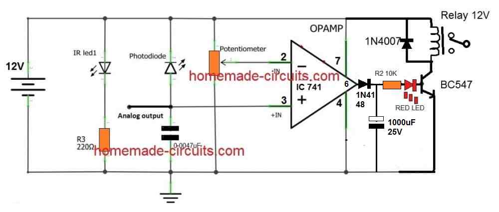
The following diagram shows how to connect a photodiode correctly with an opamp such that it effectively responds to the signals from any IR photodiode transmitter source:
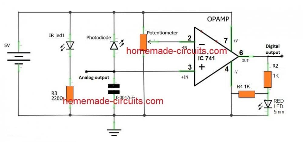
In the above diagram we can see that the earlier 10k resistor at the non-inverting pin of the opamp is replaced with a low value capacitor, and now this allows the opamp to respond to the signals generated from the Rx, Tx photodiodes.
In fact the opamp would still respond without the capacitor, however it is never advisable to keep the inputs of an opamp floating while it is powered, therefore the grounded capacitor makes sure that the concerned input of the opamp never stays floating and prone to stray signals.
You may think that the capacitor could be replaced with a high value resistor, in the order of many Meg Ohms, sorry that might not help either, that would again prohibit the opamp from sensing the signals from the photodiode, and ultimately the low value capacitor results in being the right choice.
Connecting Photodiode for Activating a Relay
The above shown opamp based photodiode detector can be further upgraded to trigger a relay stage by integrating a relay driver stage as shown in the following diagram:
Feedback from Mr. Norman Kelley (one of the avid readers of this blog):
Hi, Swagatam,
I have been looking for a circuit to alert me when someone enters my courtyard and front deck.
Delivery people leave things on the front deck and do not ring the door bell, so I don't know my packages are on the deck. Also, at night, I would like to know if someone enters my courtyard.
I designed a circuit with a PIR and a wireless TX/RX to play a message inside my house. Everything works but there are many false triggers and it drives my wife nuts.
I am assuming that the RF signals are triggering the PIR. I tried separating them a few inches and it helped, but not enough. So, I decided to look at IR to detect the person opening the gate to the courtyard and then wirelessly transmitting that trigger. I wanted to do an IR beam, but it requires more components that I don't have at this time.
So, I decided a proximity IR would work if I placed the sensor at the gate and put a reflector on the gate that would reflect the IR when the gate was opened.
I saw your above circuit "How to connect an IR Photodiode Sensor".
I bread boarded the circuit and it works fine. The only problem is it uses 50ma in standby mode and 70ma when active.
Remote mounting with battery power supply seems to be out of the question unless there is a way to reduce the power requirements or I will have to run low voltage out to the unit.
Any suggestions or comments? Thanks for your help!
Norman Kelley
My Response:
Hi Norman,
The high consumption could be simply due to the incorrect LED resistor values, try using 1K for transmitter LED and also for the indicator LED, the total consumption should come down to around 6mA


Questions & Answers
Hello.today I had an error on my boiler, and the only indication was a red LED on the front of boiler, got cold in house , but wasn’t terrible outside; however, IF this happened on a very cold day/night (I have temperature alarms in my security system ; however, the noise has to get cold before I get an alarm and that can take some time. I would rather find out immediately. I called boiler manufacturer; however, there is no ‘output’ to drive a buzzer, alarm or relay.
I do not want to simply read voltage at indicator LED because it would be a modification of boiler, and if anything happened, it might make a difference on liability.
So I am thinking of just placing a red led receiver in front of fault LED and driving relay/buzzer or connecting to my security system to give me immediate warning.
Thinking of porting led receiver in 3D printed holder that fits easily over the display fault Red LED?
Would above circuit(s) work?
Thank you.
Hi, it can be easily solved using the following circuit. You can position the LDR face to face with the boiler LED such that no external light is able to reach the LDR.
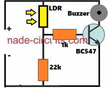
The battery voltage can be selected depending on the buzzer voltage specifications.
hey bro, can you help me,Is it matter that i use LM358 instead IC741? Do i need to use IC741 instead LM358? am pretty tight on budget, i need to make counter with IR sensor for my college assignment, am afraid that if use the wrong one, i cannot buy the another one
Hello Fahmi,
You can use either LM358 IC or 741 IC both will work, but LM358 is a better option because it creates very low output offset voltage compared to 741 IC. Meaning, even while the 741 output is triggered to a low logic it will still continue to show at least 1 V output which can be enough to keep the external transistor/relay switched ON permanently. This might not happen with a LM358 IC.
To eliminate this problem, I normally connect a series LED with the transistor base, or connect a 2.2K resistor across the base/emitter, and a 10K between base and op amp output.
Thank you, and one more thing, can i ask for your opinion about my circuit https://drive.google.com/drive/folders/1EdfqOwbYwhkBgCOG_eW71CSU6XlMRCFw?usp=sharing
The opamp photodiode circuit looks OK to me.
Thanks Bro
I am using IC555 timer and BC 547 transistor but getting wrong output. speaker and led stays on irrespective of IR led photodiode pair
Without seeing the schematic it can be difficult for me to understand the issue. Do you have the schematic diagram?
I have mailed it.
Please try removing the green LED at the emitter of the transistor and connect the emitter directly to ground and check the response.
Can I substitute the IR LED1 and Photodiode with a TCRT5000 IR LED/Receiver? I’m assuming the Collector goes to + and Emitter goes to Ground (-).
Yes you can do that, the emitter goes to the 10K and pin3 of the op amp, collector goes to to the positive.
Thank you sir. I’m using the 12v relay version of the circuit so emitter to pin 3 of the op amp and the 0.0047uF (4700pF) capacitor. Correct?
Hi Stuart, yes, according to me it is correct and should work.
Hello sir!
I assembled the circuit and it works perfectly but not the way I need: when I place a baffle between the IR LED and the photo transistor the relay coil goes off.
What did I do wrong? I want the relay to energize when there isn’t a baffle between the two.
Any help you can give will be much appreciated.
Hello Stuart, to get the mentioned results, you must swap the input pins of the op amp. So now pin#2 goes to the photo diode, and pin#3 goes to the 10K preset, this will allow you to get the intended results.
Thank you again for your timely reply. I reversed # 2 & #3 and it works exactly as I need. Great blog and website Swagatam!
That’s great Stuart, glad my suggestion helped!
I greatly appreciate your reply and a diagram as well, that’s fantastic. I am very enthusiastic about electronics and know what I require in a circuit but am never really sure where to put the components, your assistance is invaluable and very much appreciated, as we say here in Australia, “you are a good bloke” Thanks again, Regards, Alexander.
Thank you Alexander, I can understand your problem, however If you are very new to electronics then I guess you may have to first learn all the fundamentals of electronics, otherwise you may run into problems while making any electronic circuits.
In the modified diagram the pin#6 of the IC 741 is connected with the anode of the diode, and the cathode of the diode is connected with the positive lead of the capacitor. The negative lead of the capacitor is connected with the negative line of the circuit. If you are having difficulty in understanding this explanation then I am afraid you may have to first learn how to read a schematic diagram, unfortunately there’s no short cut to learning electronics…
Hi, I’m sorry but I haven’t mentioned that I am a 75 year old retired, (10 years ago), electrical contractor so I am fairly experienced in electronics but designing circuits is a different kettle of fish these days especially with the introduction all of the new components that are now readily available and their exact location in a circuit, I would have to have had a lifetime of study as you have. I am applying these circuits to my model railway where I used to use magnets, reed switches, ldr’s etc but now I am using ir components, who would have thought, which is very exciting. I can read the majority of circuit diagrams well but I don’t have the knowledge and couldn’t teach somebody else as you can, that is why I greatly appreciate your assistance. With all of the new components available these days I am just keeping my head above water and require a hand on my shoulder so to speak. With 4 children and 10 grandchildren time is at a premium for me to investigate and study the new components and their exact functions. I constructed your time delay relay circuit yesterday and it does exactly as I require thank you and I am now experimenting with the led chaser circuit for the control of a 3 aspect signalling system that I discussed with you some weeks ago and for which you supplied to me modifications for the circuit. Another question if I may, with the time delay circuit can I replace the resistor with a trim pot to make it a variable time delay to allow for the length of a passing train, the main reason for asking these questions is so that I don’t cook or waste any components, even if they are now so cheap. Regards, Alexander.
Thank you Alexander for attempting the circuits from this website and for the detailed feedback, please feel free to ask questions whenever you run into any problems, I will try my best to solve it for you!.
Yes you can replace the transistor base resistor with the trimpot, but make sure to add a 1k fixed resistor with the trimpot, otherwise the transistor may burn if the trimpot is tweaked entirely to the positive side of the supply while adjusting it.
Hello, please can i use IR receiver as photodiode on proximity sensor.
You answer is very important for me please sir help me have a nice work.
Hello Mujahid, yes you can us it as a proximity sensor, but the range will e a lot less. For higher range you must use TSOP based sensor:
How to Connect a TSOP1738 IR Sensor
G’day again Swagatam, I followed you previous advice and am very pleased, all is going well. In the circuit connecting photodiode for activating a relay, will this circuit work on a 5v supply if I am using a 5v relay that I have a supply of and if so would a 5v supply change any of the component values, is the potentiometer, vr, in the circuit a 10k value. Thank you once again for your guidance, Best Regards, Alexander.
Thank you Alexander, yes the circuit will work with 5V using a 5 V relay. No components needs to be changed except the relay. The preset is a 10k preset.
G’day Swagatam, thanks for your reply, just a follow up question if I may, if I want to make this circuit a time delay off relay would I put an rc circuit before or after the bc547, I was thinking of a 1000uf capacitor and a 10k resistor, many thanks again, Regards, Alexander.
No problem Alexander,
you can add the delay OFF feature to the proximity relay circuit using the following modifications:
The diode capacitor at the op amp output provides the required delay OFF for the relay
In this posting it is recommended to replace 10K resistor wit a .0047mfd capacitor because the resistor will decrease the input voltage.
Another site says different
“ The output of the OP Amp is connected to a LED to signal when an object is in front of the two LEDs. The IR LED produces a small current of a few micro amps and the 10k resistor is used to convert it into a voltage. This small current varies as the distance between the object and the LED varies”
Technically a resistor should have worked, but in my experiment it simply did not work until I replaced it with a capacitor. You can try yourself, and provide the feedback here…
Thanks Swagatham. You are a life saver. I replaced 10K resistor with a 3.47 nF capacitor and the range went up from 2 cm to 300 cm. Amazing. The 10K resistor was actually decreasing sensitivity considerably. Unlike your experience it worked with10K resistor. I wonder why people publish schematic with 10K resistor.
Glad it worked for you Thampi. Actually it should work with a resistor also! It is just about measuring the voltages at the pin3 and ground to check how much voltage the IR diode is able to produce and then adjust the 10k preset to approximately this voltage level at pin2. Once this is done the op amp should be able to sense the difference quickly and switch its output accordingly.
However if the voltage is too low around o.1 V or 0.2 V then adjusting the 10k precisely may not be easy, in that case we may have employ an additional preset of 1k with 10k for the coarse adjustment until finally the intended results are obtained.
Can you please tell me how I can connect an active buzzer to the op amp so that the IR turns on the buzzer? Thanks.
Simply connect the positive wire to the op amp output, and the negative wire to the negative supply line….
sir
If use IR receiver and transmitter , the Op amp out will be positive ?
how to set up for a negative switching ? I am using LM393 for switching
Ajitkumar, yes the opamp output will become positive when the IR is active on the sensor.
To invert the situation, just swap the input pins of the op amp, meaning connect the preset with pin3 and the photodiode with pin2
Hello Sir
Can you please tell this ir sensor circuit is working in sunlight / outdoor.
actually i want to make auto sanitizer machine with 1 sec out and then closed.
can i make it without micro controller, if yes then give me circuit diagram or if no then also share circuit diagram with microcontroller.
Hello Indrajeet, you can try the last circuit from the following article;
https://www.homemade-circuits.com/automatic-hand-sanitizer-circuit/
Thanks for reply, but TCRT 5000 is creating problem in sunlight
Then you should cover it from sunlight, cover it in way that it only detects the hand when it comes near the sensor
The circuit labeled “the right way” shows a “Digital output” but when I built the circuit the output is clearly analog. The circuit below adds a transistor used as a switch to drive the relay, and this transistor appears necessary to make the circuit digital.
When an op amp is wired as a compartaor the output will be always digital, because the output can be either high or low in such situations. Slight analogue behavior may occur at the transition but eventually it will a quick high or low….please check with an LED to see the response correctly, if the LED illuminates/dims slowly for the entire course of action then your op amp may be faulty. The base LED of the transistor will actually prove whether the response is digital or not.
hi dear sir thank you so much for your guidance,in the practical work related to photo diod,you directed me to this link,but i want to calculate a pulse with an approximate speed 10 KHz,but the presence of a capacitor in this circuit does not lead to my goal,photo diod is a great suggestion,but it does not have a speed circuit ,i want to make an optocopler with 10cm insulation and high speed,i mean ,i want to count a number of things through an emission pulse to an integrated circuit for example atmega or arm ,so in that case i need to be able to count it as soon as i feel the voltage ,thank you very much,
Hi Sedigh, you can try replacing the capacitor with any resistor between 1k and 1M, and see how it responds. In my experiment the photodiode did not work correctly with a resistor, I am not sure why, but you can try it and check the results.
More info is given here:
https://www.homemade-circuits.com/photodiode-phototransistor-working-and-application-circuits/
Does the addition of the capacitor in the fourth figure “the right way . . . ” affect the response time of the op-amp to a signal from the photodiode?
Possibly yes, the effect may be in microseconds
thanks for the very prompt reply. I suspected as much and I tried to use an online calculator and came up with a similar answer. Microseconds I can live with, milliseconds no so much.
No problem, appreciate your feedback!