In this article, I will show how to construct a couple of easy Arduino temperature meter circuits which can be also used as a LED room thermometer circuit.
The circuit is designed to display the readings in doted/bar LEDs. This project can be implemented for applications where ambient temperature plays a crucial role or it could be built just as another fun project for your home.
1) Using DTH11 as the Temperature Sensor
The heart and brain of the first temperature meter project is DTH11 sensor and Arduino respectively. We are going to extract only the temperature data from the sensor.
The arduino will infer the data and refresh the displayed temperature every few seconds.
We are going to take 12 resolutions of temperature sensor, in other words, we are going to take the temperature range where the ambient temperature usually vary.
If you wish to add more resolution/LEDs, you will need arduino mega to take advantage of whole temperature spectrum of the sensor with modified program.
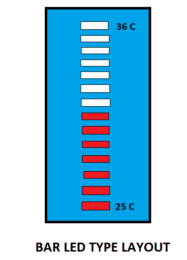
The above illustrated layout may be adopted for best looking for your setup.
The user just needs to enter the minimum temperature range of the room. It can be a rough value, which can be later changed once full hardware setup is completed.
If the temperature range goes below the threshold value that user entered, no LED will glow and if the temperature goes beyond the maximum range (minimum + 11) all LED would glow.
If there are any sensor connectivity issues, all the LED will blink every second simultaneously.
The Design:
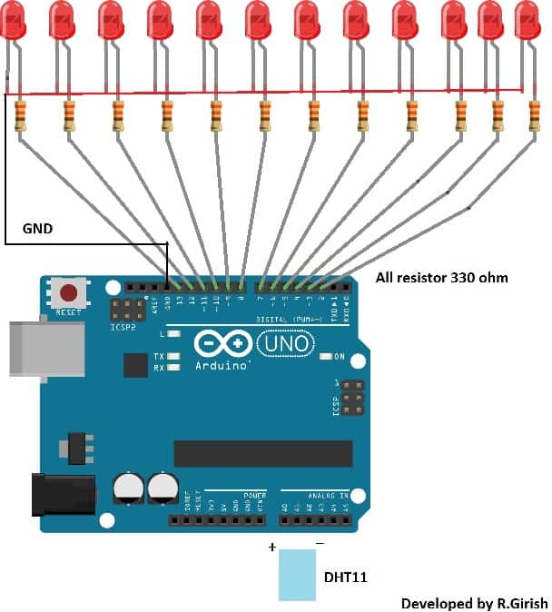
The Arduino LED temperature meter circuit wiring is very simple, a series of LED connected to GPIO pins ranging from 2 to 13 with current limiting resistors, and DHT11 sensor is plugged to analog I/O pins, which is programmed to give power supply to sensor as well as read data.
Thus, your LED thermometer circuit setup is complete and ready to upload the code. It is always recommended to test the circuit on bread board before making it permanent.
Tip: Use different color LED for indicating different temperature ranges. You may use blue LEDs for lower temperature range, green or yellow for mid temperature range and red LEDs for higher temperature. This will make more attractive.
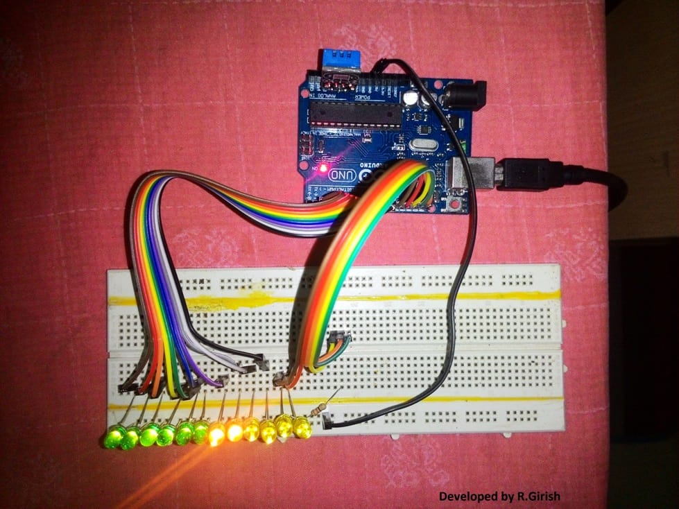
Author’s prototype:
NOTE: The following program is only compatible with DHT11 sensor.
Before proceeding, please make sure to download the library file form the following link:
https://arduino-info.wikispaces.com/file/detail/DHT-lib.zip
Program Code:
//-------Program developed by R.Girish------//

#include<dht.h>

int a=2;

int b=3;

int c=4;

int d=5;

int e=6;

int f=7;

int g=8;

int h=9;

int i=10;

int j=11;

int k=12;

int l=13;

int p=A0;

int data=A1;

int n=A2;

int ack;

dht DHT;

int temp=25;   // set temperature range.

void setup()

{

Serial.begin(9600); // may be removed after testing.

pinMode(a,OUTPUT);

pinMode(b,OUTPUT);

pinMode(c,OUTPUT);

pinMode(d,OUTPUT);

pinMode(e,OUTPUT);

pinMode(f,OUTPUT);

pinMode(g,OUTPUT);

pinMode(h,OUTPUT);

pinMode(i,OUTPUT);

pinMode(j,OUTPUT);

pinMode(k,OUTPUT);

pinMode(l,OUTPUT);

pinMode(p,OUTPUT);

pinMode(n,OUTPUT);

digitalWrite(p,HIGH);

digitalWrite(n,LOW);

}

void loop()

{

// may be removed after testing.

Serial.print("Temperature(°C) = ");

Serial.println(DHT.temperature);

Serial.print("Humidity(%) = ");

Serial.println(DHT.humidity);

Serial.print("\n");

//till here

ack=0;

int chk = DHT.read11(data);

switch (chk)

{

case DHTLIB_ERROR_CONNECT:

ack=1;

break;

}

if (ack==0)

{

if(DHT.temperature>=temp)digitalWrite(a,HIGH);

if(DHT.temperature>=temp+1)digitalWrite(b,HIGH);

if(DHT.temperature>=temp+2)digitalWrite(c,HIGH);

if(DHT.temperature>=temp+3)digitalWrite(d,HIGH);

if(DHT.temperature>=temp+4)digitalWrite(e,HIGH);

if(DHT.temperature>=temp+5)digitalWrite(f,HIGH);

if(DHT.temperature>=temp+6)digitalWrite(g,HIGH);

if(DHT.temperature>=temp+7)digitalWrite(h,HIGH);

if(DHT.temperature>=temp+8)digitalWrite(i,HIGH);

if(DHT.temperature>=temp+9)digitalWrite(j,HIGH);

if(DHT.temperature>=temp+10)digitalWrite(k,HIGH);

if(DHT.temperature>=temp+11)digitalWrite(l,HIGH);

delay(2000);

goto refresh;

}

if (ack==1)

{

// This may be removed after testing.

Serial.print("NO DATA");

Serial.print("\n\n");

// till here

delay(500);

digitalWrite(a,1);

digitalWrite(b,1);

digitalWrite(c,1);

digitalWrite(d,1);

digitalWrite(e,1);

digitalWrite(f,1);

digitalWrite(g,1);

digitalWrite(h,1);

digitalWrite(i,1);

digitalWrite(j,1);

digitalWrite(k,1);

digitalWrite(l,1);

refresh:

delay(500);

digitalWrite(a,0);

digitalWrite(b,0);

digitalWrite(c,0);

digitalWrite(d,0);

digitalWrite(e,0);

digitalWrite(f,0);

digitalWrite(g,0);

digitalWrite(h,0);

digitalWrite(i,0);

digitalWrite(j,0);

digitalWrite(k,0);

digitalWrite(l,0);

}

}

//-------Program developed by R.Girish------//
NOTE 1:
In the program:
int temp=25; // set temperature range.
Replace “25” with your minimum ambient temperature that you have encountered in past with other thermometers or predict a rough value.
NOTE 2: Please verify the temperature readings from the serial monitor and the LED setup.
2) Arduino Temperature Meter Using DS18B20
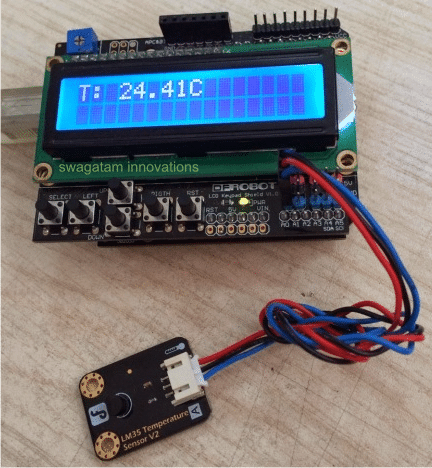
In this second design I have explained another simple, yet extremely accurate Arduino temperature sensor with Indicator circuit, using an advanced digital LCD display readout module.
There's actually nothing too much explainable in this configuration, since everything is module based and simply requires hooking up or plugging-in with each other through the offered male female sockets and connectors.
Hardware required
Four basic materials are required for constructing this accurate Arduino LCD temperature meter circuit, which may be studied as given under:
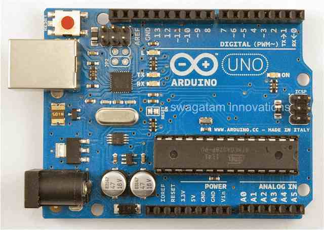
1) An Arduino UNO Board
3) An analogue temperature sensor chip, such as a DS18B20 or our very own LM35 IC.
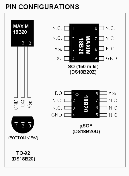
DS18B20 Digital Thermometer Specifications
The DS18B20 digital thermometer assures a 9-bit to 12-bit Celsius temperature specifications and carries an alarm feature with non-volatile consumer programmable higher and lower activation elements. The DS18B20 communicates over a single Wire bus that by description demands a single data line (and ground) for connection with a main microprocessor.
It includes a working temperature range of -55°C to +125°C which is precise to ± 0.5 ° C over the assortment of -10°C to +85°C.
Along with this, the DS18B20 is enabled to acquire power straight from the data line (“parasite power”), disposing the necessity of an
rel="nofollow" outside power supply.
Each one DS18B20 bears a distinctive 64-bit serial code, permitting multiple DS18B20s to work on the same 1 Wire bus. Consequently, it is user-friendly and uncomplicated just one microprocessor to manage loads associated with DS18B20s launched over a widespread location.
Programs that can easily take advantage from this attribute involve HVAC ecological configurations, temperature surveillance devices inside establishments, apparatus, or tools, and process supervising and regulation systems.
Pinout Details
4) A 9V, 1 amp AC to DC adapter unit
Now it's just about pushing in the connectors with each other, do a bit of setting through the LCD push buttons, and you get a full fledged, accurate digital LCD temperature meter at your disposal.
You can measure room temperature with this set up, or clamp the sensor appropriately with any heat emitting device which needs to be monitored such as an automobile engine, egg incubator chamber, geyser, or simply to check the heat dissipation from a power amplifier devices.
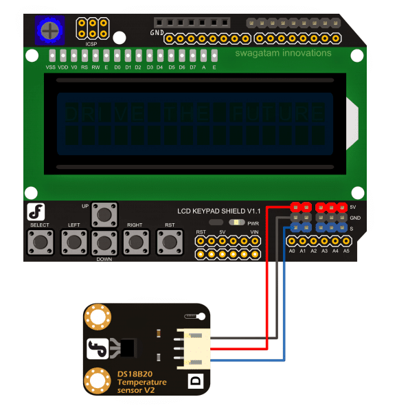
How to Hook Up the Arduino Temperature Meter
The following figure shows the connection set up, where the Arduino board is at the bottom, with the LCD monitor plugged in over it, and the temperature sensor hooked up with the LCD board.
But before you implement the above set up, you'll need to program the Arduino board with the following sample code.
OneWire ourWire(DS18B20);
DallasTemperature sensor(&ourWire);
LiquidCrystal lcd(7, 6, 5, 4, 3, 2);
byte degree_symbol[8] =
{
0b00111,
0b00101,
0b00111,
0b00000,
0b00000,
0b00000,
0b00000,
0b00000
};
void setup()
{
Serial.begin(9600);
delay(1000);
sensor.begin();
lcd.begin(16, 2);
lcd.createChar(1, degree_symbol);
lcd.clear();
lcd.setCursor(0,0);
lcd.print("Temp: ");
}
void loop()
{
sensor.requestTemperatures();
Serial.print(sensor.getTempCByIndex(0));
Serial.println("°C");
lcd.setCursor(7,0);
lcd.print(sensor.getTempCByIndex(0));
lcd.write(1);
lcd.print("C");
delay(1000);
}
Courtesy: dfrobot.com/wiki/index.php?title=LCD_KeyPad_Shield_For_Arduino_SKU:_DFR0009


Questions & Answers
Hey, thanks for the article post. Fantastic.
Hi there,
I am a student doing my B-Tech Mechanical project where I a design a solar tracker system for a parabolic dish, but have not that much knowledge on arduino uno coding, has anyone here ever done project need help please, using 2 stepper motor, one controlled by four LDR, and the other one by a timer.
need help please
Hai ,
i am padmanaban , i have seen lots of interesting projects on the web and giving solutions to the problems also. great and excelent.
can you help me to my circuit problem, here i have attached the diagram , the problem is serial communication ,
i am using atmega 16, AVR Studio, through usbapp programmer , avrdude.exe, this is the code: when i connect to the computer hyperterminal to see serial communication from microcontroller to PC terminal i am getting 95 , 47 instead 65 for A 66 for B on the terminal, BUT for U ie 85 in Decimal;, 0x55in Hex, it is showing correctly on hypertermial as 85 – ie U,
I tried with 8 Mhz, 4 Mhz ,16Mhz, 14.7456 Mhz external crystals,
Can you please Help me where I am doing Wrong,
Thanks ,
below is my Avr code and circuit diagram,
#include
#include
#include
#include
void send_char (char ch);
void mes2usart1 (char *ptr);
int main (void)
{
// initialize serial port
sei();
UCSRB = 0x98;
UCSRC = 0x06;
UBRRL = 103; // 9600 16mhz
UBRRH = 0;
//UBRRL = 95; //9600 14.7456 // 9600 BAU //UBRRL = 51; // 9600 8mhz //UBRRL = 103; // 4800 8mhz
//UBRRL = 51; // 9600 4mhz //UBRRL = 103; // 4800 4mhz
while (1)
{
mes2usart1 ("AB");
// UDR=0x55;
_delay_ms(3000);
}
}
void mes2usart1 (char *ptr)
{
while (*ptr)
send_char (*ptr++);
}
ISR (USART_RXC_vect)
{
unsigned char tmp;
tmp = UDR; // get data received through serial port
UDR = tmp; // send back data to serial port
mes2usart1 ( tmp);
}
void send_char (char ch)
{
UDR = ch;
while (!(UCSRA & 0x40));
UCSRA |= 0x40;
}
Hi padmanaban,
Unfortunately,I have no experience with AVR studio, I can't comment on your issue.
Best regards.
Mr. GR, will look into the issue and will try to solve it for you soon
Hi there would it be possible to get your contact details or pls drop me an email, I have an invention i need to discuss with you – ccjrokafor15@gmail.com
Hi, You can send it to admin (@) http://www.homemade-circuits.com
but the discussions could become a part of this website if it is interesting.