In this post I have explained the making of simple delay timers using very ordinary components like transistors, capacitors and diodes. All these circuits will produce delay ON or delay OFF time intervals at the output for a predetermined period, from a few seconds to many minutes. All the designs are fully adjustable.
Importance of Delay Timers
In many electronic circuit applications a delay of a few seconds or minutes becomes a crucial requirement for ensuring correct operation of the circuit. Without the specified delay the circuit could malfunction or even get damaged.
Let's analyze the various configurations in details.
You may also want to read about IC 555 based delay timers. Recommended for you!
Using a Single Transistor and Push Button
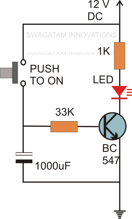
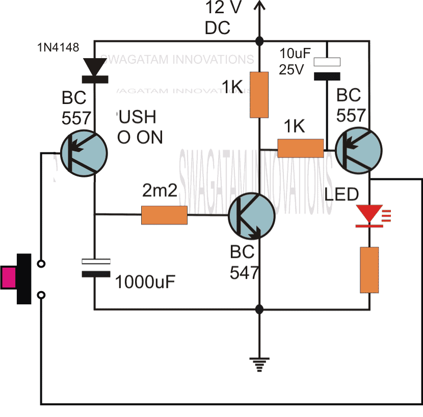
The first circuit diagram shows how a transistors and a few other passive components may be connected for acquiring the intended delay timing outputs.
The transistor has been provided with the usual base resistor for the current limiting functions.
A LED which is used here just indication purposes behaves like the collector load of the circuit.
A capacitor, which is the crucial part of the circuit gets the specific position in the circuit, we can see that it's been placed at the other end of the base resistor and not directly to the base of the transistor.
A push button is used to initiate the circuit.
On depressing the button momentarily, a positive voltage from the supply line enters the base resistor and switches ON the transistor and subsequently the LED.
However in the course of the above action, the capacitor also gets charged fully.
On releasing the push button, though the power to the base gets disconnected, the transistor continues to conduct with the aid of the stored energy in the capacitor which now starts discharging its stored charge via the transistor.
The LED also stays switched ON until the capacitor gets fully discharged.
Te value of the capacitor determines the time delay or for how long the transistor stays in the conducting mode.
Along with the capacitor, the value of the base resistor also plays an important role in determining the timing for which the transistor remains switched ON after the push button is released.
However the circuit using just one transistor will be able to produce time delays which may range only for a few seconds.
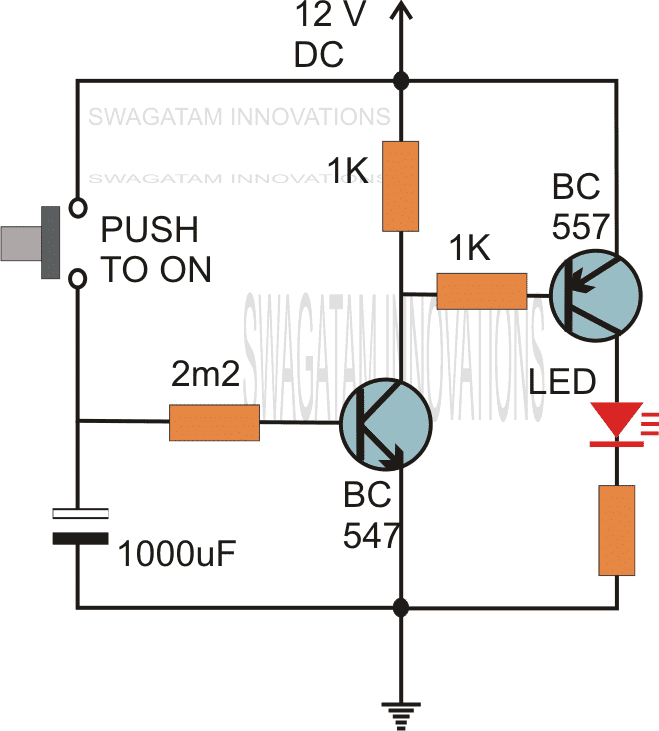
By adding one more transistor stage (next figure) the above time delay range can be increased significantly.
The addition of another transistor stage increases the sensitivity of the circuit, which enables the use of larger values of the timing resistor thereby enhancing the time delay range of the circuit.
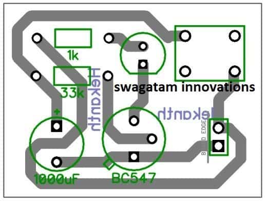
PCB Design
Video Demonstration
Using a Triac:
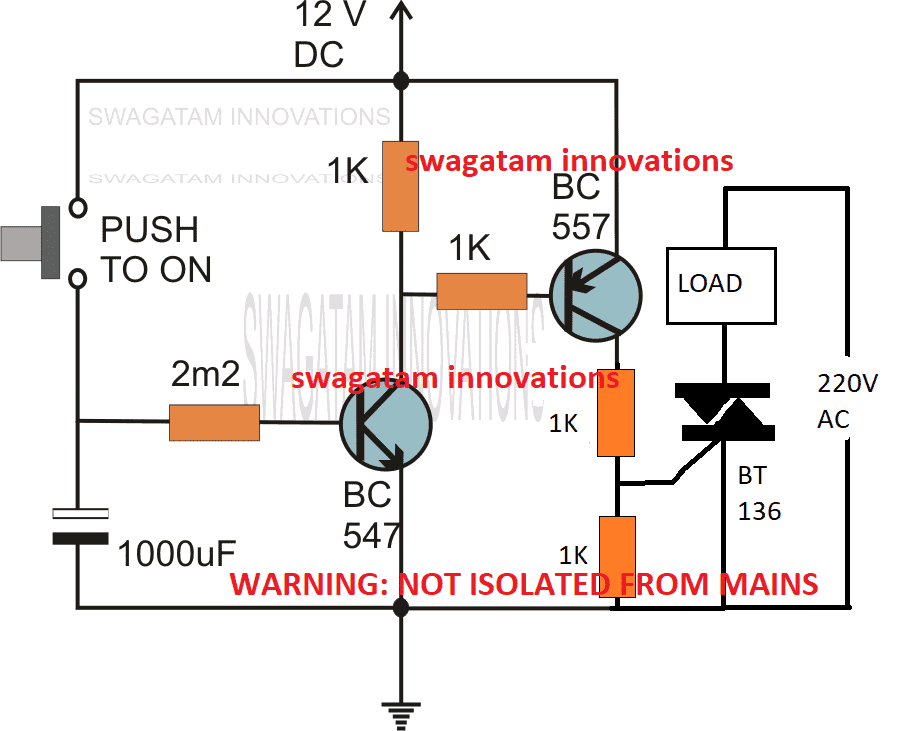
The following image shows how the above delay timer circuit may be integrated with a triac and used for toggling a mains AC operated load
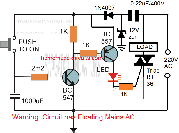
The above could be further modified with a self contained power transformerless power supply as shown below:
Without a Push-Button
If the above design is intended to be used without a push button, the same may be implemented as indicated in the following diagram:
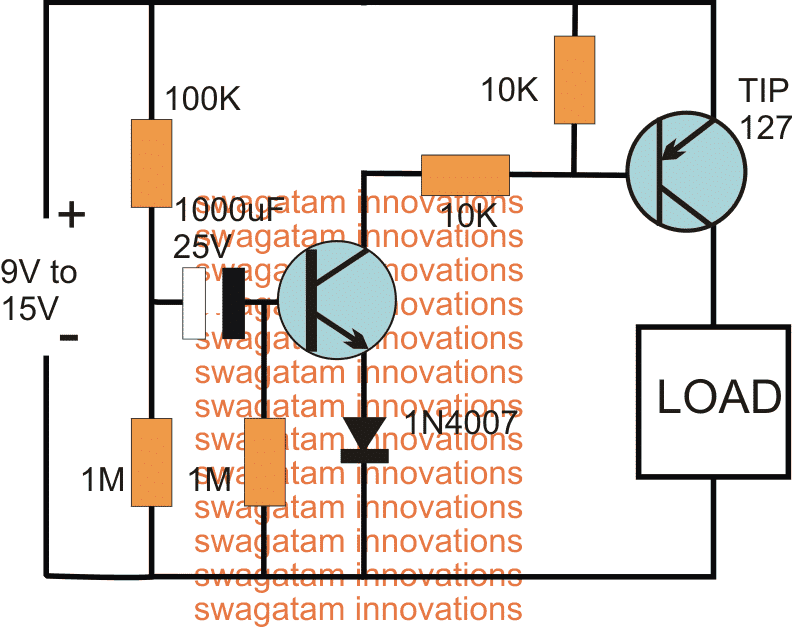
The above delay OFF effect without a push button can be further improved by using two NPN transistor, and by using the capacitor across base/ground of the left NPN
The following circuit shows how the associated push button may be rendered inactive as soon as it's pressed and while the delay timer is in the activated state.
During this time any further pressing of the push button has no impact on the timer as long as the output is active or until the timer has finished its delay operation.
Delay from an External Trigger
Problem asked by Mr. Glen (one of the dedicated readers of this blog):
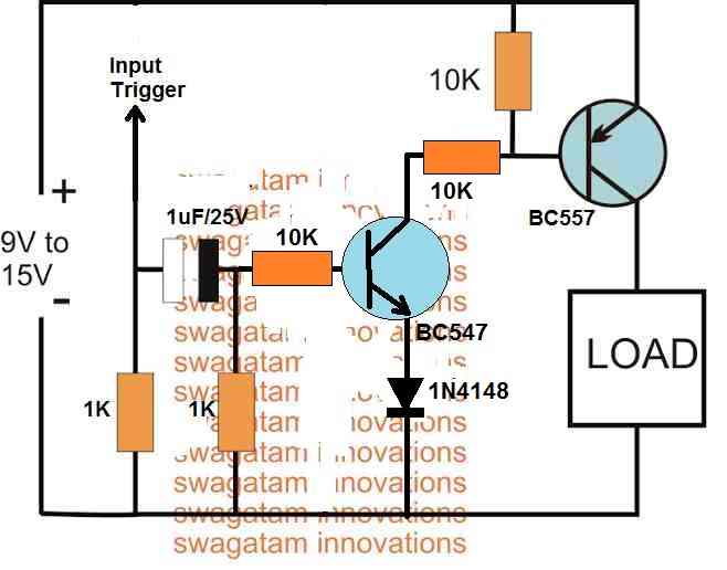
I have a situation where I have a pulse of 12V that lasts about 4 seconds (from a rotary switch being turned by a slow motor) but I only want about half a second pulse (to trigger a mechanical bell/chime).
Is there any way to take a long pulse into a circuit and send a much shorter pulse out?
The solution to the above problem is provided in the following schematic:
Two Step Sequential Timer
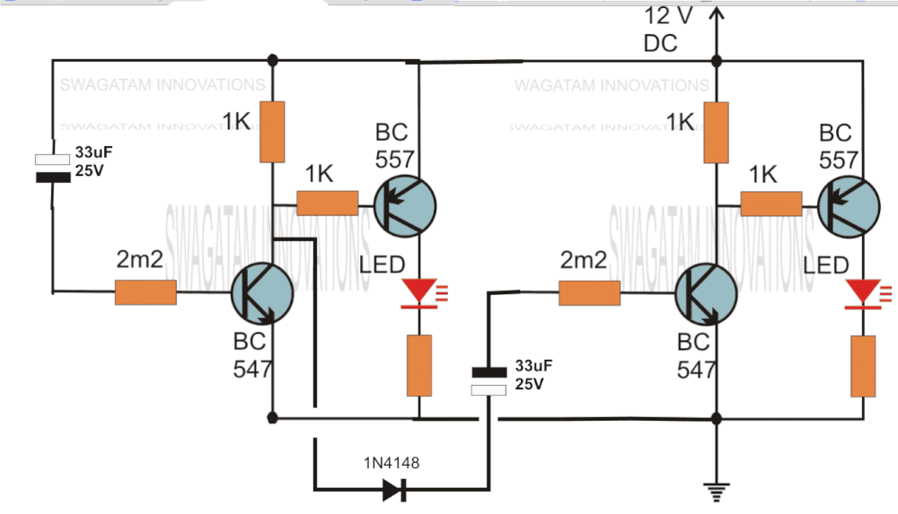
The above circuit can be modified to produce a two step sequential delay generator. This circuit was requested by one of the avid readers of this blog, Mr.Marco.
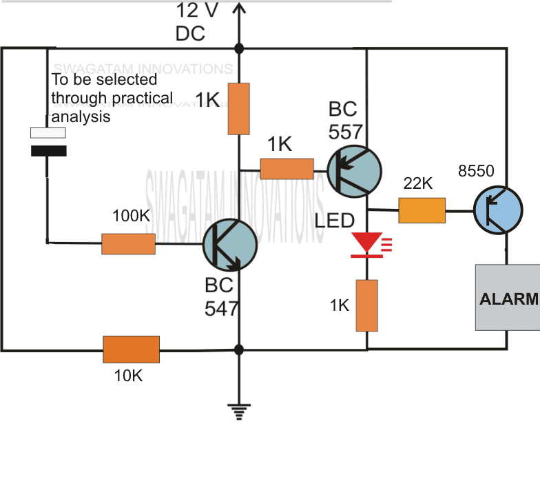
A simple delay OFF alarm circuit is shown in the following diagram.
The circuit was requested by Dmats.
The following circuit was requested by Fastshack3
Delay Timer with Relay
"I am looking to build a circuit that would control an output relay. This would be done in 12V and the sequence will be initiated by a manual switch.
I will need an adjustable time delay (possibly displayed time) after the switch is released, then the output would go on for an adjustable time (also possibly displayed) before shutting off.
The sequence would not restart until the button was pressed and released again.
The time after the button release would be from 250 milliseconds to 5 seconds. The "on" time for the output to turn on the relay would be from 500 milliseconds to 30 seconds. Let me know if you can offer any insight. Thanks!"
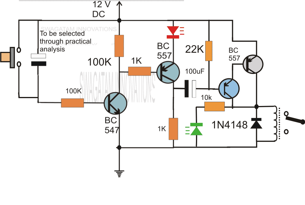
So far we have learned how to make simple delay OFF timers now let us see how we can build a simple delay ON timer circuit which allows the connected load at the output to be switched ON with some predetermined delay after power switch ON.
The explained circuit can be used for all applications which calls for an initial delay ON feature for the connected load after the mains power is switched ON.
Delay ON Timer Circuit Working Details
The shown diagram is pretty straightforward yet provides the necessary actions very impressively, moreover the delay period is variable making the set up extremely useful for the proposed applications.
The functioning can be understood with the following points:
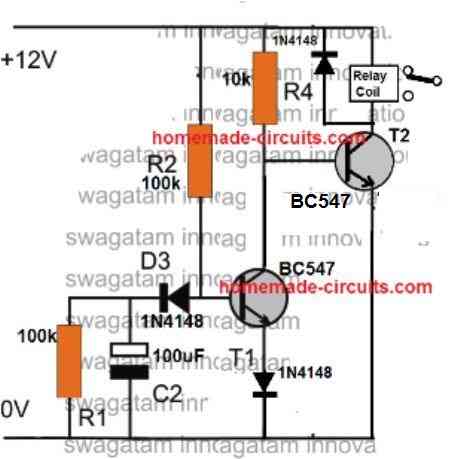
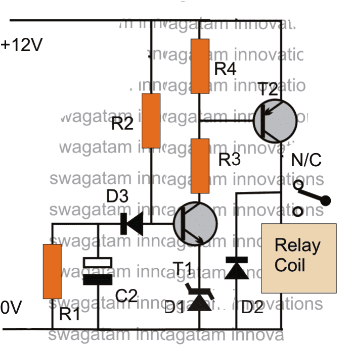
Assuming the load which requires the delay ON action being connected across the relay contacts, when power is switched ON, the 12V DC passes via R2 but is unable to reach the base of T1 because initially, C2 acts as a short across ground.
The voltage thus passes through R2, gets dropped to relevant limits and starts charging C2.
Once C2 charges up to a level which develops a potential of 0.3 to 0.6V (+ zener voltage) at the base of T1, T1 is instantly switched ON, toggling T2, and the relay subsequently....finally the load gets switched ON too.
The above process induces the required delay for switching ON the load.
The delay period may be set by appropriately selecting the values of R2 and C2.
R1 ensures that C2 quickly discharges through it so that the circuit attains the stand by position as soon as possible.
D3 blocks the charge from reaching the base of T1.
Parts List
R1 = 100K (Resistor for Discharging C2 when circuit is switched OFF))
R2 = 330K (Timing Resistor)
R3= 10K
R4 = 10K
D1 = 3V zener diode (Optional, could be replaced with a wire link)
D2 = 1N4007
D3 = 1N4148
T1 = BC547
T2 = BC557
C2 = 33uF/25V (Timing Capacitor)
Relay = SPDT, 12V/400 Ohms
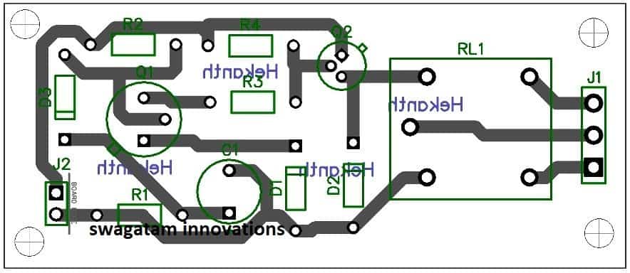
PCB Design
Application Note
I have explained how the above delay ON timer circuit becomes applicable for solving the following presented issue by one of the keen followers of this blog, Mr. Nishant.
Circuit Problem:
Hello Sir,
I have a 1KVA automatic voltage stabilizer.It has one defect that when it is switched on, very high voltage is outputted for about 1.5s (therefore cfls and bulb got fused frequently) after that the voltage becomes OK.
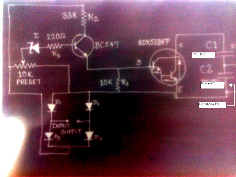
I have opened the stabilizer it consist of an auto-transformer,4 24V relay each relay connected to a separate circuit(each consisting of
10K preset,BC547,zener diode,BDX53BFP npn darlington pair transistor IC,220uF/63v capacitor,100uF/40V capacitor ,4 diodes and some resistors).
These circuits are powered by a step down transformer and output of these circuit are taken across corresponding 100uF/40V capacitor and fed to corresponding relay.What to do in order to tackle the problem.please help me.Hand drawn circuit diagram is attached.
Solving the Circuit Problem
The problem in the above circuit might be due to two reasons: one of the relays is switching ON momentarily connecting the wrong contacts with the output, or one of the responsible relays is settling down with the correct voltages a little while after power switch ON.
Since there are more than one relay, tracing out the fault and correcting it can be a bit tedious......the circuit of a delay ON timer explained in the above article could be actually very effective for the discussed purpose.
The connections are rather simple.
Using a 7812 IC, the delay timer can be powered from the existing 24V supply of the stabilizer.
Next, the delay relay N/O contacts may be wired in series with the stabilizer output socket wiring.
The above wiring would instantly take care of the issues as now the output would switch after some time during power witch ONs, allowing enough time for the internal relays to settle down with the correct voltages across their output contacts.
Feedback from Mr. Bill
Hi Swagatam,
I stumbled across your page doing research on the web to make my delay more consistent.Some back ground information first.
I am a bracket drag racer and launch the car on first sight of the 3rd amber bulb as the christmas tree is coming down.
I use a transbrake switch that is depressed to lock the automatic transmission in forward and reverse at the same time.
This allows you to rev up the engine to build power for launch. When the button is released the transmission comes out of reverse and moves the car forward under high rpm.
This is like popping the clutch on a manual transmission car, anyway my car reacts to quickly and the result is a redlight, leaving to early, and you lose the race.
In dragracing your reaction time on the launch is everything and it is a game of hundreths-thousanths with the big boys, so I have put the transbrake switch on a relay and put a 1100uf cap combo across the relay to delay its release.
Because of the car electronics I don't believe there is a precise voltage charging this cap every time I activate this circuit and precision is key so I bought a power stabilizer off of Ebay that takes 8-15 volts in and gives a consistent 12volts out.
This turned my season around but i believe this circuit could be made to be more precise and to vary the delay time in an easier way rather than swap cap combos.
Also should I run a diode in front of the relay, not currently because all that is there is the on off switch- where will the current go? I am not an electrical engineer by any means but do have some knowledge from trouble shooting high end audio for many years.
Would love your thoughts- thankyou
Bill Korecky
Analyzing and Solving the Circuit
Hi Bill,
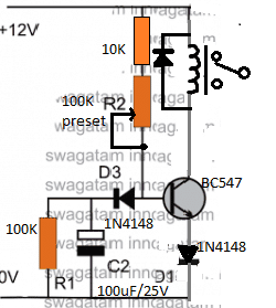
I have attached the schematic of an adjustable delay circuit, please check it out. You can use it for the mentioned purpose.
The 100K preset can used and adjusted for acquiring precise short delay periods as per your specifications.
However, please note that, the supply voltage will need to be minimum 11V, for the 12V relay to operate correctly, if this is not fulfilled then the circuit might malfunction.
Regards.
Simple 5 to 20 Minute Delay Timer
The following section discusses a simple 5 to 20 minute delay timer circuit for a specific industrial application.
The idea was requested by Mr. Jonathan.
Technical Requirements
While trying to figure out a solution to my problem on google, I came across your above posting.
I'm trying to figure out how to build a better Sous Vide controller. The main problem is that my water bath has a very high hysteresis, and when heating from colder temperatures will overshoot about 7 degrees from the temperature at which power is terminated.
It is also very well insulated, with a gap between the inner and outer vessel which makes it act like a thermos jar, because of this it takes a very long time to decline from any excess temperature. My PID controller has an SSR control output and a relay alarm output.
The alarm can be programmed as a below limit alarm with an offset from the set-point. I can use a five volt supply I already have for my circulation motor to run through the alarm relay and drive the same SSR the control output is driving.
To be on the safe side and protect the PID controller I'll add a diode to both the alarm voltage and the control voltage to prevent one output from feeding back into the other.
I'll then set the alarm to stay on until the temperature rises above the set-point minus 7 degrees. This will allow the PID tuning to be adjusted without having to account for the initial temperature ramp-up.
Because I know that last few degrees will be achieved without any power input, I'd really like a way to delay any recognition of the control signal for about five minutes after the alarm shuts off, as it will still be calling for heat.
This is the part I've yet to figure out the circuitry for. I’m thinking of a normally closed relay in series with the control output, which is held open by the alarm signal.
When the alarm signal is terminated, I need a delay on the order of five minutes before the relay returns to its ‘off’ normally closed state.
I would appreciate help with the delayed off portion of the relay circuit. I like the simplicity of the initial designs on the page, but I get the impression they wouldn’t handle anywhere near five minutes.
Thank you,
Jonathan Lundquist
The Circuit Design
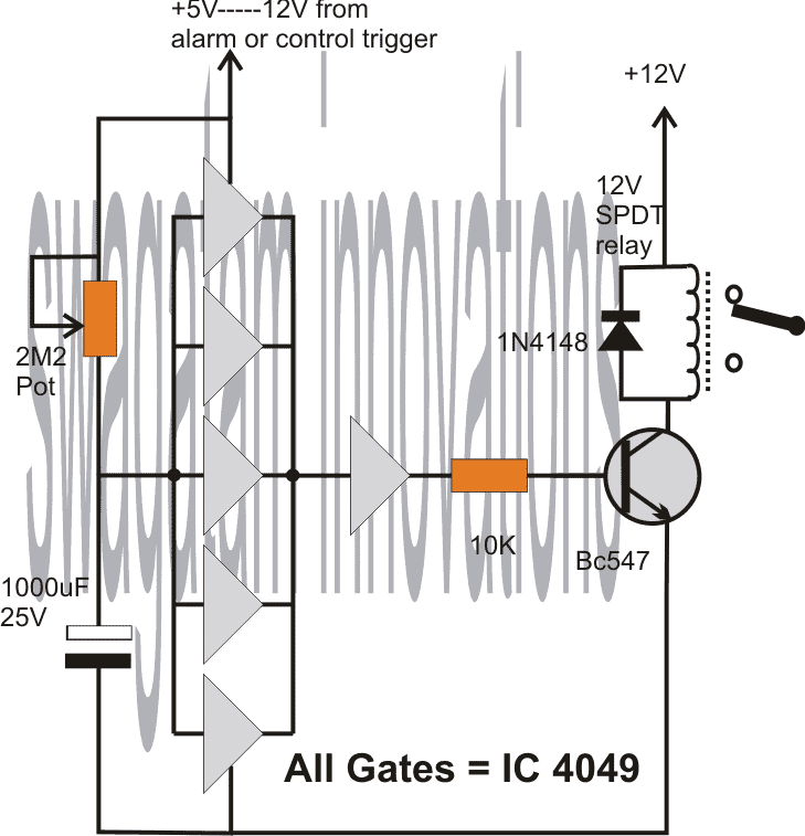
The following circuit design of a simple 5 to 20 minute delay timer circuit can be suitably applied for the above specified application.
The circuit employs the IC4049 for the required NOT gates which are configured as voltage comparators.
The 5 gates in parallel form the sensing section and provides the required time delay trigger to the subsequent buffer and the relay driver stages.
The control input is acquired from the alarm output as indicated in the above description. This input becomes the switching voltage for the proposed timer circuit.
On receiving this trigger, the input of the 5 NOT gates are initially held at logic zero because the capacitor grounds the initial trigger via the 2m2 pot.
Depending upon the 2m2 setting, the capacitor starts charging up and the moment the voltage across the capacitor reaches a recognizable value, the NOT gates revert their output to logic low, which is translated as a logic high at the output of the right single NOT gate.
This instantly triggers the connected transistor and the relay for the required delay output across the relay contacts.
The 2M2 pot may be adjusted for determining the required delays.
Circuit Diagram


Discussion & Solutions
I guess your need matches the one explained in the following article:
https://www.homemade-circuits.com/2013/06/programmable-bidirectional-motor-timer.html
Though it's quite complicated, probably it's the only way of doing it through discrete components.
Hello Sir.
I want this ckt pls help.
Make such a circuit. From which the stopped motor goes 5 seconds forward then stops for 3 seconds and then goes 5 seconds reverse. Then hold for 3 seconds. In this way the circuit continued to work.
Hello Riasat, it may be possible to design this circuit if the 5 second timing is changed to 6 seconds.
Sir this circuit I will use for automatic
Electric swing bouncer for baby.
OK, but the timing sequence should be 6 seconds and 3 seconds, to enable an easy design.
I need on time delay circuit typical of automatic voltage regulator where a single LED used as indicator blinks(flashes in on/ off order) during the delay time and then stops blinking but continues to glow normally when the load is switched ON or load relay is triggered on. Whether transistorized or with ne555 or and IC at all I need the circuit. Please I need this for my project. I will glad when designed.
I guess you had asked this question before also and I solved it for you. Please check your previous comments under the above article
The sequential timer can be surely designed, in fact I have already posted one such design in this blog, however I could not understand the connection between the motor rotation and the timing, if you could clarify that part then I could possibly suggest you an appropriate design.
Replace the push-switch in the second circuit with the tilt switch terminals with a series 1uF/25V capacitor.
I can provide a 4060 IC circuit, not a transistorized one.
Good day,
I have a 24vdc door activation circuit that I need a 5 second timer for. When the push paddles is depressed, I need to activate the latch relay for 3-5 seconds (to hold the latch open long enough for the operator to activate). Can one of your 12v circuits be modified to work with the 24vdc power supply?
Good day!
you can try the second circuit presented in the above article, replace the LED/resistor with the latch relay with protection diode.
The push button may be replaced with the paddle switch.
…the 1000uF cap should be tried with different values ranging from 10uF to 100uF for acquiring the required delay.
YES YOU ARE VERY CORRECT BUT MY PROBLEM NOW IS THAT THE BLINKER CIRCUIT HAS A LED INDICATOR ALREADY AND FROM THE SCHEMATIC DIAGRAM YOU DESIGNED FOR ME THERE IS A LED ACROSS THE BASE OF BC547 TRANSISTOR AND 1N4148 DIODE. NOW MY QUESTIONS ARE: 1 WHERE WILL THE ACTUAL LOAD BE SANDWICHED? 2. IS THE LED THERE ACROSS DIODE AND TRANSISTOR REPRESENTING THE POSITION OF THE LOAD. I AM ABOUT BUILDING THE CIRCUIT. THANKS
The base LED is only for indicating the delay period. I have added one more transistor for the load, here’s the revised diagram which you can build: The transistor can be a 2n2222 for loads below 500 mA and the base resistor can be 10K
Thank very much sir . May your days be long. I will notify you when I have completed the circuit.
You are welcome Moses, please also add a 1K resistor between the collector of T2 and the positive line.
The 12V light should illuminate and timing initiated when the tilt switch is tilted the first time or after its tilted back to its original position??? please clarify this point.
I want to create a small, variable delay. Changing the resister on the transistor base will allow the delay to be adjusted?
Using a 12v supply, can you recommend what resistance and capacitance values I should experiment with to induce a delay between 0.1 and 0.5 seconds?
you can try the second circuit given in the above article, use a 1M pot in series with a 1K resistor at the base of the transistor and a 10uF capacitor
Hey everyone,
I am looking for a time delay circuit that I can use for some drop photography. I am looking to conenct a light gate to it so that when a drop breaks the gate it starts the time delay circuit then triggers my flash gun. (flash gun has a 2 wire cable to connect to circuit). Does anyone know of a circuit which can help me? If you could include the light gate into the circuit would be a bonus.
Thanks 🙂
Swagatam… i need circuit, that after power on the circuit , output should be 5 or 10 sec, delay…Please help.
you can try this:
https://www.homemade-circuits.com/2013/02/make-this-simple-delay-on-circuit.html
Good morning sir,
I am totally confused with so many timer/delay ckts. Please refer me a ckt.
as per my requirements.
1) I want to start a 12v/500mA (max)
d.c gear motor after 40-60sec of switching on and will run untill it is switched off.
2) Another previously related problem.please refer any 12-0-12 a.c to 12v d.c rectifier ckt.with component
list and diagram……thanks…..
With regards,
K. Kausik
Good morning kaushik,
you can try the following circuit, the values of C2, R2, D1 will decide the length of the ON time delay.
https://www.homemade-circuits.com/2013/02/make-this-simple-delay-on-circuit.html
please repeat your previous request, I am not able to remember it.
hi can you suggest to me a simple circuit with 15 components for me as an electronics student …………pls i know u can help me…
hi, you can try the following design:
https://www.homemade-circuits.com/2012/04/semi-automatic-water-level.html
i want to make ten LED light using time delay feature having fed one by one after specific time day.
Hi Swagatam,
I wanted to make a timer circuit which cuts off the supply to a circuit after 5-6 seconds after being triggered , even when the trigger is still on
Hi Shyam,
you can try the following design:
3.bp.blogspot.com/-FHAn8wSZwQ0/UrFIJJpYjgI/AAAAAAAAF7I/M8L5IqLxCwA/s1600/automatic+choke+solenoid+circuit.png
ignore the relay contact capacitors and wiring set up, it was drawn for a different application.
Thank you very much….
Hi Swagatam,
I Tried the circuit which you gave , but the relay never turns off… I have changed the capacitor values ,but also no change…. can you please tell me what could be the problem.
Hi Shyam, I think I misread your requirement, the given circuit is good but is not applicable as per your need.
I'll give you a suitable one but let me know whether it should be a relay operated or without a relay, meaning the current requirement of the circuit is relatively higher or nominal??
Hi Swagatam, I wish to operate a 12v relay with this circuit. the current requirement is nominal.
Hi Shyam, I think the previous 555 based circuit which I recommended is perfect for your application and it'll surely work. Connect the relay between pin3 and ground, and make sure the line connecting pin4/8 of the IC gets the (+) 12V supply….remove the entire relay connections that's shown in the original diagram….your relay must be between pin3 and ground….let the 1N4007 diode be there with the coil, its anode will go to ground and cathode to pin3.
I thought that you wanted the entire circuit to get cut off after 5/6 sec but later realized that you wanted to execute the cut for another circuit via this timer circuit, therefore the suggested 555 circuit is right for the application.
Dear Sir ,it still doesn't work because, as I had mentioned earlier the switch remains on . Only when I turn off the switch the relay gets off immediately,there is no 5 sec delay even then.
Sorry Sir if I am bothering you too much..
Dear Shyam,
It seems there's something seriously wrong in the connections or the IC may be faulty, because the circuit is extremely standard and straightforward and should start working immediately.
pressing the push button should trigger the relay, and switch it off after the predetermined delay decided by the values of the 47K res and 10uF cap, irrespective of the switch position.
3.bp.blogspot.com/-FHAn8wSZwQ0/UrFIJJpYjgI/AAAAAAAAF7I/M8L5IqLxCwA/s1600/automatic+choke+solenoid+circuit.png
Hi Swagatam
Hoping you will be able to suggest a suitable circuit for a problem we are having. We need a circuit that can be fed via an engine ignition switch which will output a 12v feed to a solenoid for a short time, about a second, then power down once the feed from the ignition switch is turned off. Basically we have a piece of equipment that no longer turns off with the ignition switch, our current best option is to directly wire in a switch to the solenoid but if the circuit I describe is feasible then that would be a preferred option.
Thanks in advance.
Hi Hex,
There are a few confusions:
Do you want the solenoid to stay ON for 1 second after the ignition is turned OFF or should it be in response with the ignition switching, or is it regardless of the ignition ON time? Meaning once the ignition is switch ON, the solenoid will switch OFF after a second regardless of the ignition ON/OFF situation??
What kind of solenoid are you using, a spring loaded one or the one which requires a push-pull opposite supplies for locking and unlocking.
hello sir . i need a similar circuit but with 1 hour delay. What changes should i do?
Thankyou
Priyanka, you can try the following design:
https://www.homemade-circuits.com/2014/11/long-duration-timer-circuit-using.html
the 1000uF/2m2 components will need to selected by some trial and error for achieving the desired delay response.
how would i do a circuit like this that turn off 5 seconds after being turned on with a 12v source?
use the first circuit, connect the load or the circuit in place of the LED/resistor
Hi Swagatam
I have a circuit what is exactly like the one in "simple delay timer circuit". The only minor difference is +5V, and the major one is that it has to be approximately 1 sec "Delay ON" and immediately off again.
How would I do that?
Thank you
Hi Detlef,
In the first circuit, you can remove the 1000uF capacitor and replace the push switch points with a 100uF capacitor, now it'll behave in the way you have suggested, you may need to tweak the value of the 33k resistor in order to achieve the required 1 sec timing.
Hai, I need to place three LEDs L1, L2, L3 in a single circuit. So when I power ON the circuit means, the LED L1 should glow after 30 mins and the LED L2 should glow after 45 mins and the LED L3 should glow after 60 mins. Could u pls provide a circuit for that???
Hai, you can use a IC 555 and IC 4017 "chaser" circuit, set the 555 as a 15 minute timer astable and then use the outputs of the 4017 IC for getting the required sequences.
for 30 minutes you can just skip one output of the 4017.
make sure to connect pin15 with pin10 of the IC 4017
Thanx. I tried an 555 astable calculator to obtain 1 sec time high and 15 mins time low. But not able to obtain a correct value for R1, R2, C. Could u pls help me by giving the value for R1, R2 and C for the 555 astable circuit for 1 sec time high and 15 mins time low? Thanx…
15 minutes high, and 1 sec low will also do.
R1 = 1.3 Meg
R2 = 1.5K
C = 1000uF
Hi, Swagatam,
i need a delayed off timer working on 3v dc power supply , kindly share your idea if you have.
Best Regards,
Obaid
Hi Obaidullah, you can try the second or the third design from the above article
Dear Sir Please help me ….
I Want A Circuit Wich can Relay On 6v For 20 Second from get A Puch….
After 20 Second It Will Automatically Goes off
Again push then get on for 20 second
Thanx Sir
Dear Sharoj,
You can make the first circuit from the above article, just replace the LED assembly with your relay
Hi, for the shown circuits you can use any voltage between 3V and 24V
Hi, i need a circuit that has 1 push to make switch but can control 2 things (in this case a water pump and fuel injector) i want the water pump to be going before the injector does its thing to build up enough pressure in the hose and all this needs to work on 12V. Can you help?
Hi you can use the second circuit from top and do the following modifications:
replace the LED/resistor with a relay coil (connect a diode across the coil).
Now connect the pole of the relay with the 12v positive, N/O with (+) of the water pump and the N/C with the (+) of the injector…the (-) wires of the two units may be joined together and connected with the circuit negative.
The above mods will allow you to implement the actions as specified by you…..reduce the 1000uF value for setting the required time delay between the pump and the injector activation.
hi there, i need a 15v circuit with a push-button that when i press and hold for 3 seconds then release the circuit LED will remain on for 10-15 seconds without dimming effects. Is it possible? Thanks for your help.
hi,
the first circuit in the above article will fulfill your requirement, but you won't need 3 seconds to initiate it, just a fraction of a second press will be enough to trigger the LED for the desired length of time…
Hello. Thank you for your designs and dedication! I have 2 questions i would love if you could address.
Talking mainly about the “Single transistor with push button”, but also applies to the circuit with 2 transistors:
1) I see the LED dims at the end of the video, meaning that the voltage drops smoothly instead of abruptly. Wouldn’t this cause a relay connected instead of an LED to start switching on and off randomly when the voltage passes through a value which is undetermined for ON/OFF state of the relay? (let’s say, 8V for a 12V Relay)? Even worst, if used on a dirty power supply like car automotive?
2) I’ve seen some people talking about “memory effect”, which could cause the capacitor to build up enough charge, even when disconnected form +12v, to activate the transistor and inadvertently turn on the device. Is this correct? Wouldn’t this be a problem?
Thank you!
Hi, Thank you for your questions
1) No, the relay will not chatter under any circumstances, since the voltage wold be continuously declining. The relay normally oscillates only if the voltage across it goes high/low at some point.
2) That will never happen either since the capacitor will continue to discharge through the transistor base emitter until its voltage reaches below 0.5 V
To ensure an effective discharge of the capacitor you can add a 1N4148 diode across the capacitor positive and the BC557 collector, cathode being towards the collector. This is obviously for a two transistor version.
hi mr swagatam,
is it possible i add one more LED to the circuit but it will delay on around 2seconds after the 1st LED light up and both LED will off at the same time.
Thanks for your help.
Hi Babusan,
I will have to figure it out, can't able to simulate it quickly…if it's possible I'll produce it in the above article soon…
hi swagatam,
sure, hope to hear from you soon. Thank you in advance.
sure, thanks!
Hi Swagatam,
I am impressed with the simple design you manage to came out to create a time delay without using the common 555 timer IC which most users would have used.
I am interested in the formulas on how did you manage to determine the values of the resistors and capacitors and I believe one does not simply just random pick the values and try it out to determine it. It would be great if you can provide me a rough explanation on the formulas part and also how does the circuitry works
For instance, in the section where you mentioned about adding an additional transistor to the circuit would increase the time delay but why and how does it affect the time delay? Does it have anything to do with the transistor switching on/off and meanwhile does it mean the more transistors the circuit has, the longer the delay it can provide?
Hope to hear from you soon. Thanks:)
Thanks John,
Definitely there should be a universal formula for determining the RC timing values, however determining the same using a practical trial and error method is much simpler than solving the formula.
If you are interested to know regarding the formulas, you can refer to the following wikipedia article:
https://en.wikipedia.org/wiki/RC_time_constant
By adding more transistors we are making the circuit more sensitive to the voltage rise across the charging capacitor…so if one transistor requires 0.6V to trigger, with two transistors we could reduce it to 0.3V with three transistors it can become more sensitive and trigger at 0.1V..this improvement allows smaller capacitors to be used and generate longer time delays…however making the circuit more sensitive can make it prone to false triggering from external spurious signals, that's the drawback, although this can be tackled by adding caps across the base/emitters of the transistors.
Hi Swagatam,
Thanks for the link and explaination on how the side effects it will cause for having more transistors and it really give me a better idea of how the circuit work out. Currently I have another quiry which is why when do you use a pnp transistor and connect in that format instead of using the NPN transistor and connect back the similar connection like in the first circuit?
Does it have any differences? (like lesser power consumption? neater? lesser voltage required?)
Hope to hear from you soon:)
Hi John, the PNP transistors activates in response to a negative (-) pulse at its base…the in the discussed design the NPN is supposed to produce a negative pulse when activated which is intended to be responded by the next stage, and therefore a PNP stage is used in that position.
together they make the circuit more sensitive than a single NPN
Hi,
I need a circuit which has two out on and off.
I mean one on and the other off and reverse with transistor or mosfet.
Thanks
Hi,
I need a circuit which has two out on and off.
I mean one on and the other off and reverse with transistor or mosfet.
So i can pulse it with 555.
Thanks
you can use a 4047 IC…a 555 will not be needed as it has it's own oscillator.
Hey, I need a circuit that can delay a signal output to a electric motor. I would be using a 9v battery to
power the circuit and a contact switch to turn it of and on. I need the motor to turn on about 0.5s after the contact switch is pressed and to stay on until the contact switch is no longer pressed.
you can use the following circuit:
https://www.homemade-circuits.com/2013/02/make-this-simple-delay-on-circuit.html
adjust C2/R2 appropriately for the intended delay period….you can eliminate the emitter zener diode D1, since it's required only for longer delays.
Hi!
I need a circuit with auto stop when the dc motor stops.
Thank you so much for the article! I am working on a analog circuit that controls the glowing time period of a bulb.
I'm using a relay,2 resistors and 2 capacitors,one is electrolytic and the other one is ceramic. I understood the role played by electrolytic capacitor i;e it stores enerygy but I'm unable to figure out why on earth is the other capacitor used for. PLEASE check the link for circuit
Hi Swagatam Majumdar
I find that circuit requested by Fastshack3 is useful to my case, well…. almost, since it require 12V signal to activate. Is there any way to activate the circuit with ground or 0V signal?. Thanks in advance
Hi balakutak,
you can do it by eliminating the BC547 stage and replacing the collector/emitter position with the push button and the capacitor.
the base resistor of the BC557 could require an increase to may be upto 100k
Hello. I am trying to build this circuit –
s768.photobucket.com/user/dpbayly1/media/BMW%20X5%20Folder%20%202/autofoldmirrors_zps53079bfd.png.html – but the problem is, the time delay relays that I am using, does not reset, when the SPDT relay changes its state from NO to NC, as mechanical switch of the central pin is too fast. Is there a way to "slow" down the flow of electricity, when the pin switches? I was thinking about two coils, one at pin 87A and the other at pin 87. what do you think?
you can reduce the current to the relay coils for reducing the electromagnetic pull, but still that would create a difference in milliseconds only….
Good day
i would like a circuit that counts up in hours maybe to a maximum of 5 hours continuously when every time it is switched ON.i have been having a problem with this for a long time now.
Thank you
you can use a 4060 and 4017 timer circuit as given here:
https://www.homemade-circuits.com/2012/04/how-to-make-long-duration-timer-circuit.html
Is is possible to make a circuit that lights up a bulb but then a momentary switch can cut the power to turn the led light off? The tough part would be to keep the light off for longer than when you release the switch. I want the bulb to stay off for 5 seconds before it getting power again.
you can use the second circuit from the above article, and replace the BC557 with another BC547 transistor..after this you can tweak values of the 1000uF and the 2M2 for getting the desired off time delay
Hi, good job on these. Extremely useful, so thanks! Is it possible that when switch is pressed it only charges the capacitor but does not power on the light? The LED is only required on for 5 seconds after the switch is released.
you can try connecting a 220uF capacitor in series with the LED with a 1M resistor in parallel with this capacitor, this will probably take care of the mentioned situation.
I see this is a rather old article, but I have a small project that I need help with. I'm building a "Groundhog day" clock that will play "I got you babe" when the alarm goes off. So I need a circuit that will activate a relay after about 5 seconds and only last about 500 milliseconds. I have both SSD and mechanical relays of different voltages, so I'm pretty flexible with the design.
The reason for the delays is that the MP3 player takes a few seconds to turn on, then I have to bridge the play button to get it to play the song. I have tapped into the alarm clocks pre-amp, so the volume can be controlled by the original knob.
I will post a link to my project, once I have it completed.
Thanks for any assistance.
Instead of the above circuits the following would suit your application better:
https://www.homemade-circuits.com/2013/02/make-this-simple-delay-on-circuit.html
just make sure to add a 0.22uF (arbitrarily selected) capacitor between the base of T2 and the junction of R3/R4, this will take care of the 500ms activation of the relay
I saw that to design a latch you told to use a 100K resistor across the collector of BC557 and the base of BC547 removing the capacitor entirely. Could you please suggest a modification to this design that would de-latch the power to the same led upon click of another button.
you can add a push button across the base of BC547 and ground for the required de-latching feature
Thank you! That was perfect… but I have another question… how do I de-latch by pulling a GPIO pin from low to high? Could you please help me with this..
you can do it by adding another BC547 to the design.
collector to the existing BC547 base, emitter to ground, and the base to the high logic via a 10K resistor
Thanks for this …very helpful..:) With the above latching/delatching circuit, I am driving a microcontroller board instead of the LED. Before connecting the board, the supplied voltage comes across the points. But just after connecting the board, the voltage at the same points goes down by nearly 30% and is not sufficient to turn the board on. Is there a way we can reduce the resistor values in the circuit you provided to avoid the voltage drop? Or any other recommendations?
please try increasing the 1K resistors to 10K and see the response 🙂
what could be written while i submit synopsis for this project ??
Hi Mate,
I was looking for something like this. Can this be modified such that the delay time is less than a second. like 0.1 to 0.9.
Thanks
hi Mate,
Sorry if this is a resubmission. i want to delay the timer to less than a second. I am guessing it can be done by reducing the farad of the capacitor. Could you please advise.
Seen several modules in ebay but did not find anything that could meet my requirement.
you are right mate, just reduce the 1000uF capacitor to something like 1uF, or even less to get the intended small delay effect
Thank you mate. I don't see the 1000uf capacitor that your referring to on the last circuit. Well that is the circuit am after. What if i need to delay the energizing once i hit the switch to about a second or two. i am guessing i need to add a resistor in series to the positive end of the capacitor.
I've also tested a circuit where i just add a 10v 2200uf capacitor in parallel with a 5v Relay. I seem to get what i want, the relay stays energized for less than a second. Would that be ok to operate an ac transformer for a DIY spot welder.
I was referring to the first circuit which looks more appropriate for your requirement….simply replace the LED/resistor with a relay/diode, and adjust the 1000uF capacitor value to some lower level, and you will get exactly what you are looking for.
Connecting a capacitor in parallel to the relay coil will delay the switch OFF as well as the switch ON of the relay which probably we don't want…
Thanks A lot buddy. Your the best.
you'r welcome!:)
Hi,
I'd like to ask if some of these circuits would fit for alarm system? A few months ago my basement was robbed. Now I made very simple alarm system (opened door – ON, Closed door – OFF) and additionally installed "jail" doors. I would like to have delayed-OFF alarm (for one or few minutes), Can anyone suggest some proper and functioning circuit? [Siren properties: 12V; 150mA]
Thank You in advance
Hi, yes definitely you can use any of the first two circuits and use it for the mentioned purpose in conjunction with a reed switch and magnet assembly…I hope you know how to configure the proposed idea.
Thank you. Well I hope too that I know how to carry out. The problem is delay time, if it will be too short what should I change in the circuit to prolong alarm?
the timing can be varied by altering the input capacitor and resistor at the BC547 base individually or together. If you have problems let me know about it, I'll create the design for you.
Hi, So I've done the circuit according the second scheme, but the delay OFF time was very short (~0.5 sec). Then I changed capacitor from 1000 uF to 2200uF and resistor from 2m2 to 3m3, but delay off time extended maybe up to one second. Do you have any suggestion what should I do to prolong alarm? Thank you.
Hi, In the second diagram, using a 1000uF and a 2M2 resistor at the base of the NPN should produce a delay of over 2 minutes….if it's giving 0.5 seconds then there could be something seriously wrong with your circuit…
similarly with a 2200uF and 3M3 the delay should be well over 5 minutes.
I think you might have connected the transistors wrongly or something could be faulty in the circuit.
Hi again, might be I made mistakes, I'll check it later today. Thank you again.
OK, sure! thanks
Hello,
I have a similar requirement, but I need to reset a 5V touch alarm (by cutting power to it just momentarily) after it trips and starts buzzing a piezo buzzer for about five seconds. Thanks very much!
…the solution is also the same as explained by me in the above comment.
you mean, delay on power switch ON?
for that you will need to replace the switch points with the emitter/collector of a BC557 transistor, then connect a 0.22uF capacitor across its base and ground line, and make sure to connect two 10k resistors on either side of the 0.22uF capacitor with their free ends connecting with the positive line.
if you can interpret my advise through a drawing then I could check it and suggest you the needful.
you could send it to my email ID which is provided in my "contact" page.
Hi Swagatam. I have built the single transistor version of this for an application to hold a 3V relay on for å period after a pushbutton is pressed and the timing function works well – I can see the LED growing slowly dimmer. I have connected the relay's negative side (with a diode across to the positive) to the 1K resistor, but the relay does not latch and hold (it clicks though). I also tried reducing and then removing the 1K resistor and even the LED. Still no latch. What am I doing wrong?
Hi Glen, a single transistor will not be enough to sustain the relay operation, you may either try the second circuit or configure another BC547 with the existing one in the "Darlington mode"….this will do the job for you.
A-ha. Thanks, I'll try that.
Thanks Swagatam. I have built a Darlington bridge with two 2N2222 transistors (that's what I had available) and the relay now latches. But I cannot get a delay of more than about 5 seconds (I need 10-15.) I have increased the caps to 3 x 6800uF but when I increase the timing resistor beyond 40K it stops working – the transistor will not turn on. Any suggestions?
that's very strange, because 6800uF is huge and should easily produce above 5 to 10 minutes of delay…I think may be your relay has a low coil resistance which is causing quicker discharge of the cap.
in that case you may need to build the second circuit, and still if it does not provide the required delay then you could probably go for an IC 555 monostable circuit
Since I am now using two transistors as a Darlington pair the circuit is almost the same as your circuit two. See the circuit diagram I sent via Google Drive. I just added your cap and timing resistor and used two 2N2222s.
I agree that the coil resistance may be the problem since when I remove the relay and just use the LED the delay is much longer. The specs for the 3V relay say 60 ohms at .15W to 20 ohms at .45W.
When I replace the relay with the LED I can also increase the timing resistor beyond 40K and the transistors still turn on – why does the relay affect how high the timing resistor can be?
Does the choice of transistors have any effect?
And finally, once we solve this problem, I need to get the final circuit as small as possible. I have read that there are Darlington pair transistors in a combined package. Would these work and can you recommend a particular model?
Yes I saw the diagram in my email, it's good.
However now I understand the real cause of the problem….it's because of the 3V supply which is much nearer to the holding threshold 0.6V compared to 12V…and that's why the capacitor charge is able to reach this limit pretty quickly.
there's one option that you can try to counter this issue….connect 4 nos of 1N4148 diodes in series with the base resistor of the transistor, this will help to increase the delay significantly even with smaller capacitor.
2N2222 is OK, the problem is not with the transistor but the voltage level as explained above.
…sorry correction: the 4 diode in series will not increase the delay in fact it will do the opposite….
Sorry Swagatam I didn't understand your answer to my question above about the 5V alarm circuit. I have a signal coming from an alarm to a buzzer. I want the buzzer to go for 5-10 seconds, then momentarily cut off power to the alarm unit so it resets. Since there is continuous power to the buzzer I don't know how to cut power to the alarm after the delay.
Hi Glen, you can use an IC 555 monostable between the signal and the buzzer. This can be set for triggering for the desired length of time….but I could not understand why the alarm needs to be reset? It should have its own resetting system right?…what kind of alarm circuit are you using by the way?
The "alarm" is actually a capacitance touch board from Adafruit and I have attached it to a metal clock to be used in a sculpture. It goes off when anyone touches the clock, but at the moment it is locking on after the touch.
I could combine your timer circuit with your transistor latch circuit and use the NC relay contacts to cut off power for a fraction of a second. But I wondered if there is a way to use a PNP transistor as an NC contact and when it is turned on after the delay it could reset the alarm? (The alarm takes very little power.)
Yes, I wondered how that would help. 🙂 But I still don't understand why with the relay connected I cannot increase the timing resistor beyond 40k ohms? (The transistor stops turning on.)
The 4 diode idea would effectively work for a delay ON timer, but since here we are discussing a delay OFF timer, the idea would be disadvantageous.
the base resistor directly influences the collector/emitter current specs. as it increases the collector/emitter current delivering capability proportionately decreases.
you can refer to the following article for the formula:
https://www.homemade-circuits.com/2012/01/how-to-make-relay-driver-stage-in.html
OK, you mean to say the system requires a positive pulse for resetting the alarm…which could be probably achieved through a suitable BJT stage as soon as the delay timer is triggered…
yes that's possible.
OK, so it may not be possible to build a 10 second delay timer circuit for a 3V relay because of their low resistance (without using an IC.) Thanks anyway for all the advice.
That's correct, it's because of the higher load current and also the 3V value which is very relatively closer to the holding threshold of the transistor's 0.6V. If supply could be increased then the timing could also be increased
Your reply: "OK, you mean to say the system requires a positive pulse for resetting the alarm…which could be probably achieved through a suitable BJT stage as soon as the delay timer is triggered…yes that's possible."
The alarm just needs to have it's 5v power cut – either + or -. Could you explain what a suitable "BJT stage" would look like? Thanks!
Thanks for the formula Swagatam. I think I found a solution – I also have access to 5V in this project and when I raised the voltage to 5V the delay time increased considerably. I still need a big cap (6800 uF) but I can live with that. Maybe by experimenting with the value of the delay resistor I can reduce the cap a bit. Thanks again!
yes 5V is higher than3V so it will proportionately produce higher delay, in that case if you have access to 12V, you can apply it only to the RC network of the circuit and feed 3V to the relay…this will allow you to get much higher delays without the need of high value caps….or alternatively you can employ a voltage multiplier circuit to raise the 3V to 12V for the RC network.
you can introduce an NPN transistor in series with the negative of the alarm circuit, the supply negative now gets connected with the NPN emitter and the collector to the alarm circuit negative line, meaning the NPN now acts like a switch for the circuit.
the base is connected with the delay timer NPN transistor's collector via a 10uF capacitor, the base also has a 10k resistor connected with positive.
that's all..this would do the trick.
Thanks. But I need the transistor to provide power to the alarm UNTIL it is turned on, then it needs to CUT power to the alarm for a fraction of a second to reset it. Your solution sounds like the alarm circuit negative line would only be connected to negative power when the transistor is turned on. Or am I missing something?
the negative line is also a part of the power line, if this line is cut off, the supply to the alarm circuit also gets cut of
HI, Do you have a variation on this circuit so that after you release the switch, the circuit remains dead for about 5 minutes and then allows the switch to be pushed again?
Hi, It can done but not with few components, it might require the involvement of an IC 4017 for a sequential delay effect, and this could make the above simple design much complex.
Hello, Swagatam, and thank-you for your work on this site. It is very impressive. I wish to make a "firefly" circuit that will light an LED for 10 seconds, turn it off for two minutes, then turn it on again for 10 seconds and so continue. I want to power this by battery and hope that this "firefly" can run for several months before draining the battery. I would like to make many of these and hang them above a street. Can you tell me whether this is possible, and, if so, how would I go about doing it? Thank-you, David.
Thanks David, a 20 second/2minute timing sequence looks too slow for a fire fly simulation, it should be kind of 1/2 second ON and 1 second OFF…to actually imitate a firefly light.
anyway you can try the first circuit configuration from this link for your application, the R1, R2, adn C can be appropriately calculated through the attached software
the LED may connected across pin#3 and ground via a 1K resistor.
sorry here's the link:
https://www.homemade-circuits.com/p/ic-555-calculator.html
I'm hoping you can help me with this …. I want to add a timer circuit to a solar powered garden light. When the photo cell goes dark and turns the LED on, I would like a timer circuit to turn the LED off after an adjustable period of 4 to 5 hours. The lights are powered by a single AA battery. Thanks.
I'll try to design and post it soon….you can check back some days later
Thanks for considering this.
Have you had a chance to look into this yet ?
actually I already had a similar design in this website….I have modified it as per your request and posted at the bottom of the same article, please check out the last diagram posted in this article
https://www.homemade-circuits.com/2014/09/solar-garden-light-with-programmable.html
It would be so helpful if you could tell how to make the time 30 s
Hi Swagatam,
Good day…
I hope you can help me with this, can you make me a circuit where-in when the door open,it will give an alarm so that i can hear it so that i know that what i am doing is already finish. And also,can you put a reset switch to clear the alarm once i attended to it…Thank you very much.
Hi, you can use a reed relay and magnet mechanism for sensing the opening or closing of the door.
the alarm can made by using 555 IC timer, I'll try to update the diagram if possible..
Hi,in the first circuit, once I press the button and release it, is the LED working only because of the potential provided by the capacitor, or does the battery have some effect on LED even when the button is not pressed?
Hi, the capacitor is responsible for the delay only, the LED is getting its power from the supply
Can you tell me how to calculate the time constant for the first circuit? I used the formula T=RC, and used the value of base resistor as R, and got a time constant of 33 seconds, and the time to fully discharge a capacitor is 5T, that is 165 seconds, however practically it took a lot more time to discharge the capacitor. Can you please explain why this happened?
you can find the formula in wikipedia easily…
for discharging the capacitor quickly and effectively you can try the following design instead
https://www.homemade-circuits.com/2014/11/long-duration-timer-circuit-using.html
Sir, I want a simple continuous time delay buzzer ringing every 2 or 3 minutes with volume control, buzzing time 5 seconds. Please provide me Circuit Diagram.
Prachi
praneelpune@gmail.com
Prachi, you can try the second circuit from this link
https://www.homemade-circuits.com/p/ic-555-calculator.html
by some trial and error identify the values of R1, R2, C such that T1, T2 are as per your timing specs…that is T1 could be 150 seconds and T2 could be 5 seconds or vice versa.
once these are fixed you can add a buzzer across pin#3 and ground for the required results
Is there someone here that would be able to give some tips about how design this circuit?
I am building a combat robot for my kids, I am a machinist; this circuit is over my head.
The purpose of the circuit is to activate an air powered flipper on a combat robot.
I need a list of components and circuit diagram.
I can do the soldering.
Here is how it needs to work.
The circuit has 2 inputs:
Input 1 is 24 volts connected to LiPo batteries
Input 2 is a trigger also 24 volts
Output 1 is energized when the input 2 (trigger) is energized. It supplies current to activate an air solenoid that has a 24 volt 24 watt coil. After it is energized, it will stay on for 1 second and then turn off. (this supplies air pressure to raise the flipper)
Output 2 is energized 0.5 seconds after output 1 is turned off. It will remain energized for 2 seconds, then turn off. It also supplies current to activate a second air solenoid that has a 24 volt 24 watt coil. (this releases air pressure to allow a spring to lower the flipper)
Should I be able to do this with a circuit directly or should I expect to make the circuit low amps and use external relays?
you will need two of the following circuits
https://www.homemade-circuits.com/2014/11/long-duration-timer-circuit-using.html
and integrate the relay contact with the second circuit for executing the mentioned procedures.
please make a single module….. test it if you succeed then we can proceed for the final integration.
the 2m2, and the 1000uF will need to be drastically reduced for achieving the 1 second relay ON/OFF time….
Hello there, I am student in electronics, and I was given this circuit (Two Step Sequential Timer) to rewrite it on SPICEnet, and do allkinds of simulations on it. I would like to know if any of you have any xperience in SPICE and how to simulate on it. If not I would apreciate if anyone could atleast explain me how the circuit works, and wich are the cruical elements in it.
Thanks!
Why i can't use dc motor with first circuit? It work fine with led but it didn't work when i replace a dc motor for led.my dc motor even work with 1.5v voltage.what can i do? Thank u and sorry for my bad english
because motor require much larger current than LED….just replace the BC547 with TIP122 and it will start working
HI, the circuit I am looking for is a latch which will toggle states as a flip flop will, but will not change states unless the button is held down for say 4 seconds. This is to emulate the digital life we have become accustomed to. State does not change unless we long push. I'm sure many of us wanted this circuit without knowing we did. Thanks
you can make the following circuit
https://www.homemade-circuits.com/2013/08/single-push-10-step-selector-switch.html
connect a series resistor with the push button and dimension this resistor value for getting the 4 second delay
and replace pin#10 with pin#7
ignore the relay stages, you can replace them as per your preference.
helo sir i made circuit very last one 4.bp.blogspot.com/-TFvftGeJn-4/UUVoW5r9OvI/AAAAAAAADmo/JxjM1N5U5Vk/s1600/sequential+delay+relay+circuit.png
and found an error that relay continously turning on and off i mean it is triping again and again also please tell me capacitor and resistance values for veriable timing range 10 sec max thanks in advance.
one more thing that i want to turn manually on the circuit and after pushing the button it turns the relay on for 3 to 10 sec varible and then turn the relay off and when again i push the button it again run relay for required time and then set the relay in off state… can this ciruit will work( very last one)
the relay cannot oscillate since there's no feedback loop in the circuit…I am not sure what may be causing this. The concept is very simple and is explained in the article.
you can connect a 1n4148 diode in series with the BC547 base and see if that helps to rectify the issue.
Hi,mr.Swagatam,I'm looking for a substitute for a NipponDenso starter relay, which is used on a Kubota truck to shut down the diesel engine after switching the contact key to "0" position. In order to do so, after turning off thr contact key, the original timer relay activates a valve in the high-pressure fuel pump for few seconds, which leaves it without fuel and the engine shuts down. The sequence can be repeated only if the key is switched back to "ON" position, and then to "OFF".
With other words the circuit I need should activate the output relay (and hence the shutdown valve) for adjusted time only by passing the control input (the contact key) condition from "ON" to "OFF" and not the opposite otherwise the engine will not start.
As long as I can see, the last shown circuit (requested by Fastshack3) does the right sequence of actions for me. Correct me if I'm wrong. Thanks in advance!
Hi Ivan, sorry I am finding it difficult to compare your existing relay sequence with your required circuit sequence.
Do you mean to say that you want the delay timer relay to be controlled through an external push button and not directly by the contact key?
or is it the entire sequence that you want to control through a push button by completely replacing the NipponDenso starter relay
please clarify so that I am able to help you further.
if possible please provide a step by step operational details of the circuit
Sorry for the missunderdtanding! I'll try to explain better.
1) The Denso relay is burned out and is out of production (nowhere to find it), so I need another circuit to repeat it's functions.The Denso company names it "starter relay", but in fact here it's used as a shutdown one.
2) The external signal of 12V that controls the relay comes only from the contact key, no buttons of any kind.
3) The diesel engine has a 12V electromagnetic shutdown valve which purpose is to stop the fuel to the injection pump, so the engine stops working when the user desides to shut it down.
4) The relay should close the circuit of this shutdown valve for few seconds only when the contact key is switched from "ON" to "OFF"(i.e. the engine is working and it needs to be shutdown). It (the relay) should not do anything when starting the engine (i.e. when the contact key is switched from "OFF" to "ON"), because if it closes again the shutdown valve for few seconds in this case, the engine will not start.
OK got it! for an accurate performance you may have to employ an IC 555 based circuit as shown in the first diagram of this article:
https://www.homemade-circuits.com/2016/11/intruder-position-indicator-security.html
Here please remove the piezo which is connected with R2, and feed the (+) input from the contact to this R2.
The LEd and its resistor will also need to be removed and replaced with a relay, as shown in this example article:
https://www.homemade-circuits.com/2014/06/input-trigger-synchronized-monostable.html
please see only how pin#3 of the IC needs to be connected with the relay, ignore the rest.
that's all, this will take of your requirement.
In the diagram from the first link, R3/R2 and C2 can be tweaked for setting up the desired delay time.
Hi Swagatam, congratz on the good work. I also look for a same solution, in the reverse of the above.
I have simple $5 dollar alarm which is activated when a cord is pulled.
I do not want the alarm to ring for more than 2 minutes (100dB)..
When we replace the push button for the capacitor, will the capacitor create a currentleakage and drain the battery in a few days time?
Thanks, Ronald
Thanks Ronald, no it won't drain the battery, because as soon as it gets charged it will behave like an open circuit across its terminals.
Hi Swagatam,
I build the simple delay timers. They work just fine with the push button. Nice work!
However, as you have explained it is possible to remove the capacitor from its position and put it in place of the push button. This way the delay on-switch will result in the reverse, that is, in a circuit that will switch off in 2 minutes after giving power.
I removed the switch button and replaced it with the capacitor. However, it does not seem to work; the LED keeps on lighting infintely. How is this possible when the capacitor is fully loaded after a few seconds and should not feed the base? (also, after a few seconds the LED looses a little bit of intensity)
What I am looking for seems simple, my 9V boat alarm to shut down automatically after 2 minutes, so when I am not at home, the neighbourhood does not go completely haywire. The alarm gives 145 dB and will scream for hours! I only need to scare away the burglers.
Can I build this with a capacitor-transistor solution, without the use of a relay?
It looks the solution might be simple.
Thanks again.
Hi Ronald,
Both the designs will behave in the same manner, that is they will switch ON initially then switch OFF after the predetermined delay.
I think your capacitor could be leaky, because normally any capacitor once charged fully will not conduct any further…to prevent this leakage you can try adding a diode in series with the emitter of the NPN transistor….I'll try to update a more appropriate circuit soon in the above article for your reference.
Hello Sir,pls What Is The Value Of The Unknown Transistor?
which resistor are you referring to?
Hi,
I have this device which runs on 3.7v li-ion battery
Require a simple button to activate the Same.
How much power will the first circuit consume during idle mode
Hi, all the circuits shown will not consume any current during idle mode, however these are delay circuits, pressing the relevant buttons will produce a specified delayed output
hello sir, I’m planning to build my breaklight to perform like this clip (F1 style)
https://www.youtube.com/watch?v=PQh-0bRqx3c
I did manage to buy a tiny circuit that do the flashing part, but it flash continuously
So I’m in need to build a dead simple relay circuit to perform the steady lit part, with a delay of 2 sec after connect the power supply
My led array consist of 16 leds, and there is not much room left behind the board
Could you give me a hint?
Hello Minh, due to my slow internet I could not watch the video, are you looking for a relay oscillator circuit that will switch your existing flasher after certain time interval? Just like we have in police car strobe light flashers where the lamps flash rapidly between their ON/OFF intervals??
I hope I understood your requirement.
Hi Swag, I want my brake light to operate like this: [hit and hold the brake] > light flash flash flash (maybe for 1 to 2 seconds) then lit up steadily
The “flash flash flash” part was solved with a little prebuilt circuit ($1.5), wired serial in between the power source and the light
Now I need a delay circuit to bypass it after 1 or 2 seconds to get the “steadily lit” part
Thanks in advance
Ok got it, instead of shutting the lamps during the intervals you want them to stay solid ON, this can be done using any standard IC 555 flasher circuit as shown in the below article
https://www.homemade-circuits.com/2016/07/alternate-switching-relay-timer-circuit.html
ignore the existing wiring of the relay contacts, and replace it as given below:
connect the N/O and the pole of the relay with separate wires and connect the ends of these wires across the transistor which is controlling the flashing of your lamps, or whatever “switch ” that’s used for the flashing of the Lamp
…sorry I thought you wanted the process to keep repeating…if the lamps are required to stay ON permanently as long as the brakes are applied in that case the above circuit will not work…instead you can try the first circuit as given in this article:
https://www.homemade-circuits.com/2013/02/make-this-simple-delay-on-circuit.html
wire the relay contacts exactly as explained previously
I see, so instead of using a relay to turn off the flasher and switch to continuous power source, you just let them run in parallel. So the led will be solid on after the time is up and the continuous power is on, am I right?
yes that’s right, just make sure the delay timer’s PNP is appropriately rated to handle the LED current.
so to get a 1 sec delay with that circuit what value of R2 & C2 should be used? base on your experience
Since I don’t have all those parts around to test which suit my need and have to buy them new in bulk quantity
R2, C2 will need to be experimented to get the required delay, and since 1 sec is very less, you can replace D1 with a short link….you can even eliminate the relay if you are able to configure the PNP transistor’s collector with your lamps.
the 12V to this circuit will come from your brakes….
in the end, I still have to go along the try-redo way
about the “PNP transistor’s collector” you mentioned, I have almost no knowledge about it since I’m new to this electronic stuff and still learning
All my electronic knowledge came from the days at elementary school, now it comes from gg 😀
Thanks alot for your help. Good day, sir
it’s always fun to have try-redo in electronics, and for this circuit it could be just a matter of minutes to finalize the delay parts.
If you can explain how your LEDs are configured with your flasher circuit, I may try to solve the PNP configuration details for you.
my led array consists of 16 leds, divided in to 4 parallel rows.
in each row there are 4 leds with 1 330ohm resistor wired in serial.
the array is running fine with 12v source from my brake switch for 3 years
hope you can figure it out, thanks
OK, but how is it connected with the flashing circuit, through a relay or transistor?
right now it connect directly in serial with the flashing circuit, no thing in between
use separate diodes for supplying the positive voltage to the LED module, one from the flasher and one from the delay timer, this will do the job.
meaning, break the existing flasher positive connection and put a diode in the middle.
next connect a diode from the collector of the delay timer PNP and join it with the LED positive line
Hi Swagatam, I am trying to built IOT with esp8266-01 (wifi module) to operate the 5V relay my circuit. Every think is working fine but if I will restart the system wifi get stuck (may be the drawback from load). If I remove the esp GND from relay GND wifi restart normal and after few seconds connect the GND again and working normal.
I want to add delay for 02 Sec between esp and relay.
Thanks,
Hi farid, you can try the following delay concept and see if it works for you?
https://www.homemade-circuits.com/2013/02/make-this-simple-delay-on-circuit.html
Sir,
I would like to make a 10 minute delay circuit to be fitted via a relay of 3v, to power up the water motor pump. It should use either button cells of 3v or 6v. Can you suggest a suitable circuit so that when powered on the water pump will run for 10 minutes and shut off.
Gyaneshwar,
you can try the following concept:
https://www.homemade-circuits.com/long-duration-timer-circuit-using/
make sure to replace the BC557 base 10K with a 1K
Thank you Sir for responding very very fast.
My circuit design will require to use buton cells to power up the circuit. This circuit will have to switch off the AC motor pump after exactly 10 minutes. So please let me know whether such circuit is available to run a relay of lower battery voltage.
If the supply is rated at minimum 6V, then a 5V/6V relay can be tried, however this will demand relatively high current from the cells and can deplete it quickly.
you can go for a triac instead, that will work better.
Thank you Sir for the reply. Can you name a triac to be used int he circuit instead of the transistor (i.e. label of the triac). The circuit will remain the same and the TR will be replaced by the TRIAC. Right!
Hello P GNANESWAR , I have updated the required diagram for you, in the article
I need a circuit for solar panel of say 12v to power a sump motor pump of 0.5hp. Could you please suggest any so that I can build by myself at home.
assuming your motor is rated at 220V, you will need a 500 watt inverter, a 12V 150 AH battery and a 18V 20 amp solar panel which you can directly connect with your battery for charging it, although a having a controller would make things more favorable for the battery…
I seek a simple transistor-based timer circuit for use in a car. There is a light which has two functions: one is to illuminate the rear number (licence) plate and the other is to illuminate the boot when the boot lid is raised and the general car lighting is off. I want the light (drawing about 1 A at 12 volts) to switch on when the circuit is first powered by opening the boot lid, and for the light to stay on for five to 10 minutes then switch off while the circuit remains powered (boot lid open and switch still ‘on’). The circuit would be reset when the boot lid is closed and the circuit is open again. In the particular car there is also a small relay which is, I think, normally closed, linking the light to all other lighting in the car. I assume that when the boot lid circuit is powered, it goes open and isolates the light from the rest of the car’s lights.
Thank you.
you can try the following design
the trigger from the boot lid cab be connected to the base of the BC547, this will switch ON the connected LED at pin#3 of the IC, and will keep it ON for a time period determined by the values of the 100K pot and the 220uF capacitor.
I have an LED light strip that has white and red LEDs. In order to light the colors independently, the manufacturer suggests using an on-off-on rocker switch. The LED strip has three wires.
However, in my application I can only use a simple on-off switch.
I’m looking for a circuit that would allow me to achieve this:
Turn switch on: RED lights
Turn switch off then back on within 4 seconds: WHITE lights
If more than 4 seconds go by after the switch is turned off, the next time it turns on: RED lights
I have some bulbs from a company called Imtra that does this, but they do not make light strips and I would like to achieve the same results.
Can you help? Thanks!!!
It will require some thinking…it seems it can be accomplished with a 4017 IC circuit and a delay timer…
Hello, for the last diagram, what is the number unknown transistor
It is also a BC557
Hello, for the last diagram, what is the number unknown transistor in dalinton pair with Bc557 on the relay coil
Hi,
could you please suggest me a simple circuit for “Delayed ON IC”? ( The IC should get the supply or turn ON after 3 seconds after switching ON the circuit)
Can you tell me the IC number because different ICs may have a slightly different way of implementing this….a general way can be to connect the positive supply pin of the IC through a 10 k resistor, and add a 100uF capacitor across this supply pin and the negative line
Am using IC 4093. +’ve pin is pin 14. The should get the +’ve supply after 3 seconds. So can I implement the same as u said?
yes for IC 4093 there’s no other way but to use the resistor capacitor method which I suggested earlier
Thanks. Will try. The connections is like , from the +’ve power supply to the 10k resistor, from 10k to the IC pin and the capacitor is between +’ve and -‘ve or IF and -‘ve?
yes 10k between positive line and Vcc pin of the IC….capacitor across the Vcc pin of the IC and the negative supply line of the IC
positive of the capacitor will connect with the junction of Vcc pin of the IC and 10K
How to make the IC555 to get the power supply after 5 Seconds? I tried the above one as mentioned in the previous comment with resistor and capacitor. It doesn’t work.
one of the above circuits will definitely work if you appropriately modify the design it as per your needs.
anyway you can also try the last circuit from the following article:
https://www.homemade-circuits.com/make-this-simple-delay-on-circuit/
replace the relay with the IC 555 supply pins, meaning connect the IC 555 +Vcc pin directly with the positive line, but connect the negative pin#1 of the IC to the collector of the BC547
I would like a circuit to be built to control water flow from sump to overhead tank. The sensors should be positioned in such a way that it should be installed in the sump as well as overhead tank. In the sump to ensure the motor does not run dry. In the overhead tank to ensure it does not overflow and also not emptied fully.
Actually I already have quite a few similar circuits, these can be suitably combined or modified for any preferred water level control operations..
Hi,
I am looking for a way of delaying a signal so that large relays get the time to switch on, they are then latched with one of there own contacts.
The action comes from a sensor on a garden railway track that pulls a wire to 0v when a train passes over.
At present, sometimes the train is too fast to close the relay.
Your first example here would be fine, I reckon it would work with the 24v we use.
Unfortunately it needs to have an input that connects the 0v just for a moment instead of connecting the 12v to the base of a transistor and the capacitor, is this possible?
Thanks.
Hi, You can probably try the 5th diagram from top with some further modifications:
ignore the push button, connect the base of the BC557 with the 0V input source through a 10uF capacitor, positive of this capacitor should go to the base of the BC557. Make sure to connect a 220 ohm resistor in series with this 10uF just to safeguard the BC557 from high base current.
Also connect a 1K resistor from the outer negative end of the capacitor to the positive line so that the capacitor is able to discharge after the completion of each trigger
Hi Swag,
Thanks for the reply and sorry for my delay. I am now going to try to implement the delay.
Can I just confirm the drawing we are looking at is the one called the ‘two step sequential timer’?
Do I disregard the connection to the anode of the led and just connect to the base of the left BC557 with the capacitor and resistors?
Thanks.
Hi Bob,
you can try the following design
yes you can disregard the feedback loop and configure the base of BC557 as per your requirement.
However the feedback ensures that as long as the LED is ON, the circuit would remain locked and not respond to any spurious or accidental input signals.
i want a circuit which having a user defind relay.
There is push button in the circuit.
If i press the button for X time the out get high after x time.(Simply on led after x time).
If i press switch for 1 second then led will be on after 1 second……
sorry that looks difficult using discrete parts, a microprocessor based circuit could possibly solve it..
thank you for your reply.
Yes,it can be done by microcontroller….
Maximum delay is 5 sec ….
Now can it be possible by discrete parts ?
I think it can be possible using discrete parts, but while pressing the button some time will be used, so that much time may affect the end result…suppose you take 2 seconds to press the button 5 times, then this 2 seconds will affect the output delay time. so there should be another button which can be pressed after the trigger button is pressed 5 times, this idea may help to get the correct delay results.
Hello Swag,
Thank you for your reply,
Actually in my application, i just Have to Flash a LED.
Now the LED need to be flash at a perticular time after pressing the switch. (We need to creat a ON time dealy)
Ex :- If I press the switch for 1 Second, The LED need to be flash only after a time interval of 1 Second (After releasing the switch).
During this time(1 second) the switch will be press one time only.
Hi Ashok, OK I understood.
What will be the maximum time delay range, is it 5 seconds or more? please specify.
maximum 5 sec……
OK, but the delay ON timing will start after you release the button…
yes ,delay time start after releasing the pushbutton…..
OK let me think, I’ll try to find a solution using discrete parts
Hello swag….
Is there any solution for our application….
You can try the following design
all the diodes are 1N4148.
The IC 555 output timing must be adjusted to precisely 1 second ON + OFF
The output capacitors must be also selected such that each capacitor produces a delay of roughly 1 second.
The circuit interconnections which are not shown with black dots are not connected.
Hi
Im mark
Im trying to make a circuit that will send an OFF signal after x1 seconds then send ON signal after x2 seconds
And loops
I thought bout the 555 timer and a relay but how bout looping
Could u help me with this
Hi Mark, you could try a 555 and 4017 chaser circuit, pin#2 of 4017 would then give you the first x1 OFF time, next pin#2 could be combined with pin#4 using diodes for getting the 2X ON time. The subsequent Pin#7 could be connected with pin#15 for the looping action.
Hi
Your designs are so simple and effective. But For the above delay on circuit i am not able to find R1 – 610k anywhere in market. could you please help me out.
Thank you, glad you liked my circuits. The 610K is not critical, you can use any other value depending on how much delay you need at the output. Higher values will produce higher delays and lower value will give lower delay intervals.
I am sorry, R1 is for discharging the capacitor so that the circuit becomes ready for the next cycle, it is not for the delay periods, R2 decides the delay…you can use 100K for R1.
I am trying to design a circuit (I can use a 555). But I am getting lost. I need to
Output is off on power up and until I “trigger”
The trigger (which is momentary switch) (Can pull high or low)
Delay (from 250 msec to 750 msec – by swapping out resistors/capacitors)
After the delay, the output switches on – can use a FET. (I need to drive about 500ma on the output)
Ideally, I would like operating voltage from 1.5v up to say 16v and be able to have +/- 10% on the delay timing
Can you help me out or give me some thoughts on this
With a IC 555 the output will be ON for the set delay period and then switch OFF, but you want the output to be permanently ON after the delay has elapsed which looks difficult using a IC 555, but can be done using a few BJTs.
HI, I’m new to electronics but have played around with 12v relays and LEDS for various projects for awhile. I came up with a project to make an automatic chicken coop door. I used a pre-built light sensor relay to open and close the door via double pole latching relay (relay acts to forward and reverse the motor to the door) My issue is the chickens never get in on time and often 2-3 are trapped outside looking through the perspex door. I have been researching using IC555 chip along with a IC4020b to make a timer (standard flexi/interval timer project). I stumbled across your site and thought I could adapt the “delay on” circuit I just need to incorporate an LDR so it delays about 1hr after dark to move the relay from NO to NC and then during the day the LDR allows the relay to go to NO. I know I need a configuration of an LDR and transistors to make this work, could you offer any advice.
Hi, for the mentioned requirement you can modify the delay ON timer by including another BC547 transistor. Connect its collector/emitter across R1. Next connect its base at the junction of an LDR and a 100K resistor. The LDR will be on the positive line side while the 100K will be at the ground side.
When the light is insufficient on the LDR, the BC547 will slowly switch off allowing C2 to get charged via R2, and finally switching ON T1/T2. The relay will be at N/C during day time, and at N/O during night
Thanks, I’ll go buy the bits tomorrow and give it all a try. Hopefully have happy chickens before the weekend.
Sure, wish you all the best!
Please sir I want you to suggest a simple circuit out of these to on for 5secs and off for 5secs continuously. Thanks
Hi Favor, these are one shot timers, you will need an astable, as given here:
https://www.homemade-circuits.com/timer-ic-555-explained/#How_Astable_Mode_Works
I have a question, how can i activate a simple delay timer with a relay that designed for 12 volts by 24 volts .Can i change the values of the resistors by doubling there values and change the relay to 24 volts keeping the RC time same thanks
You can do that, but doubling the resistor may not necessarily produce the same delay.
With the arduino based inverter circuit, is it practical to use the arduino to control the relay rather than a delay circuit? In the software, maybe after the first full loop turn the relay on?
No it won’t be a good idea, because we don’t know how the Arduino outputs would respond while booting…it could begin with both the outputs ON.
Thanks for putting all this together, its been very helpful for furthering my understanding.
I am trying to put together a project involving a raspberry pi running on a battery, charged by solar.
I want the raspberry pi to turn off when either the battery gets low or the solar panel is actively charging. The charger I am using has an output pin that turns on under exactly those circumstances, and I believe I can use that on a GPIO pin on the RPi to request a safe shut down. But when the RPi is “shut down” it apparently still draws like 100mA, which is far too much for how thin of a line I am walking with charging and power consumption on this project. The voltage booster between my battery and my RPi has a pin that will allow me to turn off power completely, but if i just cut power to the RPi it can cause corruption.
So I need to be able to request an orderly shut down via the GPIO pin, then wait long enough for the pi to turn off, and then cut its power completely.
Then, when the solar panel turns off, I want that to trigger the RPi to turn back on. I think I have figured out how to do that with 3 relays, but I think one of them needs to have a short delay.
It seems like some of the circuits you’ve described might be exactly what I need, but I’m so far out of my depth I can’t tell which one or how I would need to apply it to my situation.
Any advice would be appreciated.
Thanks Kyle, glad you liked my posts.
I tried to understand your requirement, but I am having difficulty in getting and executing the stages together in my mind.
However, if you are looking for a delay timer that would switch ON a desired relay after some predetermined delay, this can be simply implemented using the following concept:
This will switch ON the relay after some delay as determined by the values of the upper 100K, and the capacitor
Good day swag I am a solar IT student and am working on a solar powered water level indicator this indicator have the ability to auto switch ON/OFF the pumping machine and alarm to alert the use that the water un the over head thank is full. The alarm peeps continuously so am trying to control the alarm at least to peep for like 30min to 40min. Pls can you help me with a solution on how to add a delay timing ic on the circuit to control the alarm. Thank you.
Hi Joseph, can you please provide the details regarding how the alarm stage is switched ON from the control circuit? Is it through a HIGH output logic or a LOW logic, and what is a specifications of the alarm device…Once I know these I’ll b able to solve it for you.
Hi Swag
Greetings from South Africa. Thank you for the informative article. I need to pick your brains for a little project I am trying to put together for my kids. I am a chemical engineer, so electronics are not part of my comfort zone. So “Idiots-Guide-Style” answers would be appreciated.
My kids practice fencing and I want to put together portable signal boxes that would register when they manage to score a hit on their opponent. They are using epees where the tip of the sword acts as a push button switch, normally open. I am cabling the sword’s body wire to a 9V battery powered circuit. The idea is that a closed circuit lights up an LED and sounds a buzzer.
I had the circuit all worked out with LED, buzzer and the relevant resistors and was going to test whether it would work better in a parallel or series configuration. Then it dawned on me that the circuit would only function as long as the tip of the sword was in contact with the opponent, which would only be a fraction of a second.
So what I need is a circuit that would allow the LED and buzzer to stay active for 2 second or so after the switch has re-opened. The first circuit you showed, with the single transistor, would seem to fit the bill, but I have no idea which transistor and capacitor to use. I also do not know if a capacitor can charge up in the short time that that the sword tip would close the circuit.
The other idea I had was to have the sword tip activate a 555 timer which would then let the LED/buzzer come on for 2-3 seconds. Problem is I have no idea which 555 to use. The LED’s are C515, 30 mA for the one indicator box and D105, 20mA for the other. The buzzer is a 5V, 25mA max unit. Resistors are R1 5W for the series option and R47 0.5W for the parallel option.
Could you please give me some advice on what would be the best type of circuit to put together for this application?
Thanks Nils,
yes you can use the first simple circuit. For the capacitor you can use a 100uF/25V, and for the resistor you can test different values from 1M and downwards, until it gives you the required 2 second delay OFF timing.
You can also use an IC 555 based monostable design as shown below:
Ignore the 2M2 resistor and the LDR. The input trigger can be applied to the transistor 10K end. Also connect a 10K across the base/emitter of the BC547.
Thanks a stack for the detailed response.
On the first simple circuit, where should I put the 5V buzzer?
If I understand the intruder alarm circuit you posted correctly, I would leave out the LDR and replace the 2M2 with the connection to the epee tip. Two question I have is where would the LED fit in, and to connect a 10K over the base/emitter of the BC547, can I simply put it in place of the LDR or must the base connection be between the existing 10K and the base?
In the first diagram, you can add the buzzer in place of the LED/resistor.
In the 555 link, after removing the 2M2 and the LDR, the 10K end of the transistor can be applied with a momentary positive trigger for activating the 555 output. The external trigger source negative and the 555 negative must be linked in common, otherwise the 555 won’t respond….same applies for the transistor circuit also.
The other 10K must be across the base directly and the ground line, not in the LDR position.
I have drawn up a diagram of an adaptation of the first circuit. Is there any way I can send it to you to see if it would work?
You can upload it in any “free image hosting site:”, and provide the link here, I’ll check it.
Can I request a circuit where you push a button then ON and OFF are delay powered only with 3v 2032 cell
And also a Delay ON powered only with 3v 2032 also.
Thanks..
Cheers Swagatam!
Thanks Zerfallen, all the above circuits are rated to work with 3V and above, you can use them as per your specifications.
Hi,
I need a circuit 1 or 2 for driving a Picaxe micro processor (14M2/28X2, approx. 5v supply) and keep it running for about a little more than 80 sec. after interrupting the supply. That seems far off the values in your circuits. Can you suggest values to experiment with?
best regards
torben
Hi, you can try the 2nd circuit from this article…you can get even up to 5 hours delay by suitably adjusting the 2M2 and the 1000uF capacitor values
https://www.homemade-circuits.com/how-to-make-long-duration-timer-circuit/
Dear Swagatam . Could you please help me? second circuit (Delay off timer with BC547 and BC 557) . If i use 6 volt DC and If i change the LED and RESISTOR with a 6 volt relay (120 mA of coil) would it work?
thank you.
Dear Vahid, yes definitely it will work.
Hi Swag –
I’m looking for a Power-On Timer solution that may be a variation of the Section 2.3 Without-a-Button circuit. I’m powering a 12VDC 2A (sustained) solenoid. I would like the solenoid to activate when power is applied (no trigger button) and stay on for at most 10 seconds (6-10 seconds set via RC would be okay). The solenoid would then deactivate, even though power is still applied, until power is removed and then reapplied. If power is removed before timeout, the solenoid would deactivate (expected because there’s no power). I like the 2.3 circuit but I’m wondering if it could be done with just one transistor since the delay is less than 10 seconds. I prefer a transistor/triac/opto output and not use a relay (for reliability due to sparking). I will/can put a flyback diode across the solenoid coil since it does have some bite on discharge! Any ideas? Thanks!
Hi Ron, you can use a single transistor, a Darlington type such as TIP122, or TIP142 for a higher current load. You can also try a MOSFET such as IRF540 for improving the results.
Sir can you give a schematic diagram for this? How to connect MOSFET in the said circuit? I also need an automated spray (no switch button) the spray will be on due to the PIR sensor. The process must be, when the PIR sensor detects a person in front of the door, theres a 5-10 seconds delay to trigger the dc pump which will cause the spray. And i need the spray to be on for 3-5 seconds before it turns off.
Hi Jill, you can try the following schematic:
I forgot to show a 1K resistor across gate/source of the MOSFET. So please add it. The 10uF will need to be tweaked appropriately for getting the mentioned delays.
Sir can I ask on how this works? Like can you explain what happens to every component on this circuit? I wanted to know the working principle of each components. Thanks sir
When PIR detects humans, it sends a positive bias signal to T1 base, but due to C2 T1 does not conduct immediately. When C2 charges fully T1 conducts, which switches ON T2, the MOSFET and the solenoid.
When the human leaves, T1 stops conducting but T2 continues to hold the solenoid until T2 base capacitor discharges fully.
Thank u sir. But how did you come up with the certain values of capacitors and resistors? Also sir what specific model of transistors should I use for the BJT and MOSFET. Like their max current and power rating (I have no idea on this)
I have selected them approximately due to the wide tolerance range for transistors. The base RC decides the time delay with respect to the collector load. The basic formula can be studied in this example article:
https://www.homemade-circuits.com/universal-high-watt-led-current-limiter
Also sir If i were to use a dc pump what the minimum or maximum ratings should i consider? Like its min/max current, voltage and power?
I have not yet investigated charge pump circuits, so can’t suggest about it.
Sir do you know any other simulator application? I’ve tried Proteus 8 using the circuit u gave me, but it does not run the circuit. It says “AVR: Program property is not defined” and also “Real time simulation failed to start” because due to quarantine, we cant try it with the components. Hope u could help me sir.
Jill, build it practically with real and good quality components, you will get the desired results without fail. I have never used simulators because I feel they are far inferior compared to a human mind simulation and tests
Yes ur right sir, but due to the quarantine we cant go out and buy such components.
Sir is my explanation correct with regards to the working principle of the circuit “When IR senskr detects a motion, it sends a positive bias signal to T1 base, but because of C2, T1 does not conduct immediately. The RC network plays the role for the delay on timer because when the IR sensor detects motion, current begins to flow into the capacitor via the resistor, the capacitor gradually charges up through the resistor until the voltage across it reaches the supply voltage of the battery, and the resistor reduces the flow of current to the capacitor to slow down the time it takes to charge the capacitor. Then, when C2 charges fully, T1 conducts which switches on T2, the MOSFET, and the DC Pump. In addition, T1 will stop conducting but T2 continues to hold the DC Pump until T2 base capacitor discharges fully which is responsible for the delay off time.” Hope you could confirm it sir if my explanation is accurate. Thanks a lot!
Hi Jill, Yes your explanation is correct, except the C2 charging, which has to charge only up to 0.7 V to switch ON T1, rest everything is correct.
Sir why did you use transistors? Did it act as a switch? Why use transistors in that circuit? What is its purpose? Hope you can explain it to me
Thank you
Yes transistors are used as switches. When the base voltage rises to 0.7V across base/emitter, the collector emitter switches ON. The delay in reaching the 0.7 V level is controlled by the base resistor capacitor values.
Hi, I bought a 240v ac adjustable electronic repeat cycle timer, when buying it I didn’t realise it was 240v ac as I need 24vdc. I can supply 24vdc to it and get it working but the moment I put any load on the output it instantly drops from 24vdc to almost no volts. Can anyone please let me know what needs to be done to the pcb to fix my issue. I can supply photos of the pcb if needed. Thanks
If you apply 24V Dc in place of 240V AC it won’t work. You must find out the operating DC of the circuit and the supply lines of the PCB, and then apply the specified amount of DC across the DC supply lines of the board via a protection diode.
Hi Swagatam,
I am looking for a circuit for my DIY hand sanitizer. Could you please help me to figure out this issue.
Power supply for this circuit is 12V (because I am using 12V pump).
The input is from an IR obstacle avoidance sensor that will produce 0V when detecting hands and 12V in normal condition. The function is as following:
1. Pump is in standby mode.
2. When detecting hands, pump is activated immediately and running in 2 seconds.
3. After 2 seconds, pump is deactivated in 3 seconds (this will prevent pump working continuously), even IR sensor detected hands or not.
4. After 5 seconds (2 seconds activated and 3 seconds deactivated), if detecting hands go to step 2, if not go to standby mode.
I attached a diagram for better understanding.
https://photos.app.goo.gl/NCCPTeyArYRLCruh7
Thank you and hope to receive your feedback.
Rgds,
Muoi
Dear Mr. Swagatam
Appreciate your detailed responses and feedback to each query received.
I need help with the following application.
A 220 VAC load needs to stay off for a 15 second delay and then stay on for 30 minutes. This should happen on switching on a main power supply to the load.
Pls do help me with the correct circuit for the same. The application is Industrial in nature. The load current is not high (1A) and can be switched via a PCB mounted relay
Thank you Dear R Fernandes,
you can try the following concept:
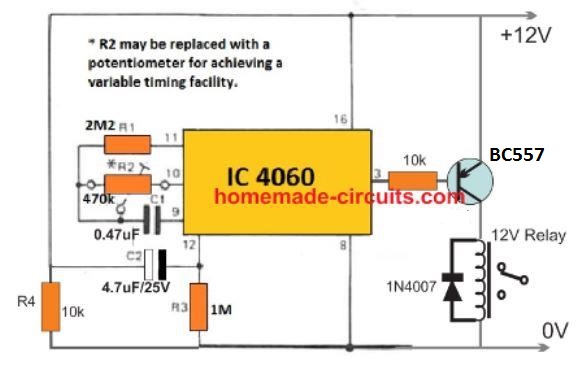
C2/R3 decides the delay ON time (15 seconds)
C1/R2 decides the OFF time.
I forgot to add a 1N4148 diode across pin3 and pin11, so please add it. Cathode will go to pin11
The timing parts are arbitrarily chosen, so you will have to tweak them to perfection with some trial and error.
Dear Sir
Your promptness and attention to detail are impeccable. Thank you very much for the help. Will have this tried and will revert with feedback once the markets open here for component procurement.
Best Regards
No Problem dear Fernandes, please feel free to revert if you have any problems or doubts regarding the project, I’ll be happy to help!
dear sir i have made above IN4148 circuit. with 2N4401 and 2N4403 transistors. but LED is always on when power supplied. any reason for that sir?
Hi Jayanath, are you referring to the second design? It requires a push button, which is pressed momentarily and released, which keeps the LED illuminated for sometime then shuts it off. If you keep the NPN base permanently connected to the supply then the LED will stay always ON
HI Swagatam
Is there a circuit you can provide that will do the following please?
1. I want a relay to operate when my cars ignition (+ve 12V) is turned on.
2. The relay is to remain on for around 5 seconds, then it will release.
3. It will not then re-operate due to the ignition switch still being on.
4. It will only operate again once the ignition has been turned off, then turned back on again at a later time.
Thanks
hi Dave, you can apply the first circuit from the following article with a little modification:
https://www.homemade-circuits.com/input-trigger-synchronized-monostable/
Please connect a 10uF/25V capacitor across the points labeled as “Left Pins”
That’s all.
You will also have to adjust the values of R2, and C1 to get the required 5 seconds precise output
The 12V supply to the circuit must come from the ignition switch
Excellent, thanks so much Swagatam for that and for coming back to me so quickly.
I have now got all the components and will put it all together in the next couple of days.
Cheers
Dave
That sounds great Dave, let me know if you have any problems!
Hi again Swagatam,
Made up the circuit on a spare bit of Vero board I had, then tested it’s functionality under all conditions. And the verdict….perfect!
Thanks again Swagatam
Now all I have to do is wire it into the car.
Thanks Dave, and glad you could build it without any issues, hope it works in your car also.
I sincerely appreciate your circuits for the delay on or the delay off. Would it be possible to show a circuit that does both – a 3 second delay on (no momentary switch) before turning on the led and also supports a 3 second delay off (when the power of 3v is turned off) before turning off the led? Not looking to cycle the on-off but instead support a one time delay on and if on long enough to charge the capacitor, also support a delay off. Would this be possible with the fewest electronics?
It can be probably achieved with the second design through some minor modifications, as I have explained below:
The switch points should be shorted. The 2m2 should be replaced with two series 1M resistors, and the capacitor should be placed across the junction of these two 1M resistors and the ground line.
For an enhanced effect, the emitter of the NPN could be connected to the negative via a 1N4148 diode
Thank you Swagatam for the super fast response.
Two questions:
1. For the first two diagrams, I was able to get them to work perfectly at 12V. Very nice. What would change for only 3V (actually 2.1 to 3V) rather than 12V? (This application uses two AAA batteries that may be rechargeable to drive the led, hence the low voltage).
2. I tried making the changes you suggested to the second diagram but when I move the capacitor to the junction of the two 1M resistors, the led fails to go on at all. If I move the capacitor back, only the delay off portion works as before but no delay on. Would it be possible to email a diagram that supports both a delay on and delay off that works for 3V?
If the requests are out of line, no worries, please let me know and again thank you for all your help.
No problem Bob, however the two resistor and a center capacitor network should definitely work, regardless of the supply voltage.
You can try reducing either the resistor values or the capacitor value and check the response, you may find the circuit working exactly as per your required specs.
For 3 V the emitter of the NPN must be directly linked with the ground without a diode.
Hello, Good morning…
Wow, lots of questions and comments.
I’m trying to find one of your designs and suggestions in here to power a computer ON and OFF with a IR remote. Not sure if this is the best way the go, but i would like to find out if possible.
The computer power button use 5v, when pushed it shorts the connection (like 0.5 sec needed).
Could you suggest a best option/design to accomplish this, please.
Or you think will be best to go a different route like using a 555 or perhaps an Attiny85 mcu, or ???
I have see many circuits, getting confuse which way to go.
Thanks a lot for your time and any suggestions.
Good Day
Hi, if you are sure about 0.5 second ON/OFF trigger for the button start then it can be easily done with a 555 IC based IR remote control or even an ordinary RF remote control, which looks more convenient since the whole module can be cheaply procured. In fact the momentary ON/OFf system is already included in those systems.
Please how can I restart the 2nd circuit without discharge the capacitor, because it works first, but doesn’t restart after reconnecting without shorting the capacitor to discharge it
The answer is given in the transistorized version presented in the following article:
https://www.homemade-circuits.com/how-to-make-long-duration-timer-circuit/
Hi Swagatam,
I have been working on an alarm that will drive a prerecorded Chinese music alarm chip. The alarm chip needs clean 3v to operate correctly. The alarm would need a delay when power was applied so the alarm module could be placed. The alarm would need to be activated by light. For example, the alarm would be powered on and placed inside of the refrigerator. when someone opens the refrigerator door, the alarm would sound and if they close the door, the alarm would continue to sound for say 1 minute. and then would shut off and not reset. The circuit would have an led to indicate that the alarm had been triggered. This led would be a flashing red led and would only light when the alarm had been triggered. I built the alarm with a LM358 using one side as the alarm trigger and the other side as the delay. I tried adding your latching transistor circuit and it worked. The problem with my circuit is if you block the LDR the alarm goes silent and it doesn’t shut off after 1 minute. Once the time delay is over the circuit remains high forever. I have the output from the LM358 feeding a NPN transistor that grounds a 555 one shot, but it never shuts off due to the input from the LM358 being continuous. I tried adding a 0.1uF capacitor with resistors on both sides to the positive rail and it still would not shut off. The grounding resistor from pin 2 of the 555 is driven from pin 1 of the LM358. Do you think you will have time to design such a circuit and post it on you site? Thanks for your assistance.
Hi Norman, I don’t think op amps would be required for the application, you can probably use the following 555 monostable for the purpose:
The LED can be added in parallel to the speaker for the blinking effect.
Hi Swagatam,
I forgot to mention that I will be powering this circuit with 3 AAA batteries. The chip will work on 3-4.5v
Hi Norman, if you apply the circuit suggested by me, you can use a CMOS IC 555 and use a 4.5V comfortably.
Hi Swagatam,
The circuit you suggested works great for the delay off for the alarm. What would you suggest for the delay on part of the circuit? I need to be able to power on the circuit with a delay so I can place it in the dark space without the alarm sounding prematurely. Thanks!
Hi Norman, You said that
“the alarm would be powered on and placed inside of the refrigerator. when someone opens the refrigerator door, the alarm would sound and if they close the door, the alarm would continue to sound for say 1 minute. and then would shut off and not reset”
The 555 circuit would do exactly the same…. I cannot see the delay ON action need anywhere in your requirement…
Initially, for the first time the alarm will sound while installing the system inside the fridge, but once installed, the 555 circuit will sound only when someone opens the fridge door.
Hi Swagatam, I found a delay ON circuit that works. It is another 555 circuit that has pin 7 not connected. Pin 2 and 6 are shorted together. A 470uF cap in connected to pin 2 or pin 6 with the negative leg and the positive leg connected to VCC. A 47K resistor is connected from pin 6 or pin 2 to ground. When the circuit is powered the capacitor keeps pin 2 positive until the cap reaches a point and stops transferring to pin 2. The 47K resistor allows pin 2 to be grounded and then pin 3 goes high. Pin 3 is connected to the base of a BC548 with a 1K resistor. The emitter of the BC548 is connected to ground. The collector of the BC548 is connected to the base of a BC327 with a 1K resistor. The emitter of the BC327 in connected to VCC. The collector of the BC327 is connected to the positive rail of the circuit you gave me. The negative rails are common. I tried this with out the transistor pair and it worked, but was weak, so I added the transistor pair. I also added the same transistor pair to the output from your circuit as it provided a little more power to the music siren chip. I love your circuit. I tried to find it on your site so I could understand exactly how it works, but I couldn’t find it. Would you mind explaining how your circuit works. I understand some of it but the diodes are confusing to me. Thanks again for your quick response. You are the best!
H Norman, that looks just the opposite of a monostable operation. As long as the capacitor keeps the pin2 high, the output pin3 remains low, and as soon as the pin2 becomes low, the output pin3 is pulled is high permanently.
Hi Swagatam,
OK, I am still working on the Refrigerator Alarm. The delay circuit and your one shot circuit work fine. I wanted to add a latched LED (Flashing type) to indicate that the alarm had been triggered. I have tried several circuits with no success. The most promising looked to be using a BT169. I connected it with a 10k resistor from the transistor pair from pin 3 to the gate. I connected the LED from 5v to the anode and connected the cathode to ground through a 2k2 resistor (to protect LED). It works until the 555 times out and then the LED is off as the alarm is off. If I remove the 1uF capacitor from the circuit, it works. The LED flashes even after the 555 times out. which is what I want. It indicates the alarm has been triggered. The problem is ,without the 1uF capacitor, the alarm will sound anytime it receives light. So when the mother comes home and opens the refrigerator door, the alarm sounds and she has no idea if the kids have been in the refrigerator. I am sending by email a schematic of my circuit. I hope this is not aggravating you. Thanks for your help!
Hi Norman, do you mean the whole circuit should be latched and “frozen” when the door is opened by the child, until reset manually.
So when the child opens the fridge door, the alarm sounds and latches the LED. Next, when the mom opens the door the alarm does not sound, and the mom sees only the flashing LED, realizing that the fridge had been opened before by someone.
Yes, exactly!
This can be achieved through a single IC 4060. Use its pin3 to activate the buzzer, also connect a diode from pin3 to pin11 for latching the buzzer.
The buzzer should be connected across positive line to pin3. The LEd could be wired across pin4 and ground for getting the flashing effect.
Hi Swagatam,
I really don’t understand your last comment with respect to the cd4060. So, I used the first 555 delay circuit to allow powering alarm without the alarm sounding on power up. I then used your 555 one shot circuit to allow the alarm to activate with light and sound for a preset time and then not re-alarm when light is present again. I then used your transistor latch circuit to latch a flashing LED, which indicates the alarm has been tripped. The circuit works good and I am sending you a schematic by email. Thanks again for you help!
Hi Norman, If you connect the IC 4060 exactly as suggested by me, you would be able to get all those required features through a single IC.
Hi Swagatam,
Ok, I bread boarded the 4060 circuit as you suggested as follows: The positive for the KD9561 alarm is connected to the positive rail. The negative of KD9561 alarm is connected to pin 3 of the 4060. The LED is connected from positive rail to pin 4 of the 4060. The 4060 will not sink enough current to play the KD9561 alarm, so I added a PNP transistor. Pin 3 of the 4060 is connected to the base of the BC327 PNP transistor with a 1K resistor. The negative of the KD9561 alarm is connected to the emitter of the BC327 PNP transistor. The collector of the BC327 PNP transistor is connected to ground. When power is applied, the KD9561 alarm sounds until the 4060 times out and the diode latches it with a high output from pin 3 of the 4060. The KD9561 alarm stops and the LED stays lit, which is correct. I can add my delay-on 555 circuit to allow powering on the circuit without the KD9561 alarm sounding, but I still need a way to only turn on the 4060 when LIGHT is present. I haven’t been able to find any example circuits using LDRs to activate a 4060 IC. Maybe I’m missing something. Assistance please. Thanks!
Hi Norman, for LDR triggering, connect pin12 of the IC to ground through the LDR, and also connect a 220k from pin12 to the positive line.
Hi again Swagatam
Having now completed a timer circuit based on your design, I now want to build a door alarm circuit that will be triggered by the opening of switch (maybe a reed switch).
This will set of an alarm by the operation of a relay for a set period (maybe 30 seconds) then it will turn off.
I see that you have done circuits for the above however using the 555 but I cannot see one that will fit this final requirement.
That is, once the alarm has completed its operation, then I do not want it operating again, even if the door (reed switch) is left open or is closed or opened again. The circuit can only be reset by manually operating another switch.
The circuit can run off a voltage of 9 – 12 dc volts.
Regards
Dave
Hi Dave,
You can try the second circuit from the following article:
https://www.homemade-circuits.com/loop-alarm-circuits-closed-loop-parallel-loop-series-parallel-loop/
You can eliminate the extra switches S3, S4, and replace S2 with your reed relay.
The SCR can be a C106
If you want the reset switch to be a push-to-ON type, then you can use the same in parallel to C1, and replace S1 with a wire link.
Hi Swagatam
Thanks for the quick response.
I understand that the alarm will be audible until such time the reset switch is activated in this circuit. However I maybe didn’t make it clear that I only wanted the alarm to be audible for around 30 seconds and then turn off. Then it would require the manual reset switch to restore the circuit back to its normal state where its waiting on S2 to open.
Regards
Dave
Hi Dave, I got it, you can try the following circuit with some modifications:
Replace the switch S1 with the anode/cathode of an SCR.
Next connect the reed switch across the positive line and the gate of the SCR, and connect a 1k across agte and ground of the SCR
Hi Swagatam, I’m slightly confused about the reed switch going between the +ve rail and the gate of the SCR. Because the Reed switch will be normally closed when the door is closed, which will mean that a positive voltage will be applied to the gate of the SCR turning it on and causing the 555 at 3 to go high and activate the alarm. Or have I got something wrong?
Regards
Dave
Hi Dave, In that case, simply reverse the configuration. Connect the reed between SCR gate and ground line, and connect any resistor between 1k and 10k between gate and positive.
Hi Swagatam,
Ok, I have now tested it and found the following.
When the reed switch opens the SCR latches and applies a low state to pin 2 of the 555. Then Pin 3 goes high and operates the relay. All good so far. At Pin 6/7 the voltage then gradually rises until it exceeds the 2/3 supply voltage. But Pin 3 stays high and the relay does not release.
Is this because the SCR is still latched until the supply voltage is disconnected, so it will continue to supply a low state to Pin 2?
In a separate test with the reed switch closed and the SCR not latched, I momentary applied a low state to Pin 2 and the relay operated then released after the timeout. All good.
If the SCR being permanently latched is causing the relay not to timeout, then what I would like is for the relay to operate after the reed switch opens then for the relay to release after the timeout period. Irrespective of how many times the reed switch closes and opens during the timeout period or after the relay releases. Its only by removing the power supply and reconnecting the supply that it will restore the circuit to normal.
Look forward to your thoughts on this.
Cheers
Dave
Thanks Dave, I think the following modification in the previous diagram should perfectly take care of the issue that you facing.
The capacitor in series with the pin2 of the IC ensures that the latching of the SCR does not have any effect on the pin2 of the IC 555
Hi there,
I’m not sure if this is entirely relevant to this article, so apologies in advance, but looking for input/ideas from someone that knows far more about electronics than I do! I’m wondering whether it would be theoretically possible to do some of the things mentioned above for a potentiometer (for an analog stick on a video game controller). Essentially, I’m wondering whether its possible to create a circuit where moving the stick (say to the right) will register an input for a very brief window (say 1/60th of a second) before instantly returning it to the neutral voltage of the potentiometer (as if the stick was in its neutral position) despite still being held. Then, when the stick is released physically, it would be ready for this process to repeat. This essentially would work to eliminate the “hold” input of the stick and simulate it being a very precisely timed button press.
Sorry, I’m aware this is a very poor explanation; I’m not an electrician! This is more of an academic interest with a mind to modifying my hardware if its within the realms of possibility!
Thanks very much for reading!
Hi, do you mean creating a momentary time delay pulse of 1/60th second through a pot movement at its extreme end?? Yes that can be done through an op amp attached with the pot resistance..
Hi and thanks for such an informative article. I’d like you to please help me with this, at it seems I’m not able to get a solution.
There is a microprocessor that needs a delay to be set when being powered up. The BE line needs to be switched from low to high 100 ns after the RESET line.
I explain again: when being powered up, the RESET line switches from low to high (0 to +3.3v). And 100 nanoseconds *later* the BE line also needs to be switched from low to high.
How can I achieve that
Thanks.
Hi, thanks, you can apply the +3.3 V to the BE line through a PNP transistor and delay the transistor conduction through a resistor/capacitor network at the base of the transistor
My fridge at start up draws much power. i need a simple circuit design to control it from getting damaged as i feel it may. pls is it adviceable to keep using the fridge that way or to get a deigned circuit to cause a delay of inflow power in it?
Thanks
Ugo
That looks quite normal to me, fridge motors or any other motor will always draw higher current at the start up. If you prohibit this it can cause malfunctioning of the system
Hi,
Like most people I am flicking through the internet looking for a solution to a particular problem.
I want to monitor a train on a model circuit, when it goes over a sensor (in this case one track connected to the other by the train wheels, the common rail has 0v on it so the input to the circuit would start its timer when it sees a 0v signal) nothing happens initially when the train leaves the section and the signal is no longer there then a relay is closed for a second (after a short delay, say 3 seconds, to cover for a dirty rail).
The way I am trying to do it is to charge a capacitor and keep it charged while the signal is coming from the track, if the wheel misses for a second the capacitor would start to discharge but it will see the signal again and recharge so not get to the point when the relay closes till it has seen no signal for about 3 seconds.
Would the delay on timer circuit above do this?
Thanks.
Bob.
Hi, I have never used a model train, so I am having difficulty in understanding the situation, there are many things which are not clear, like, where should the circuit be, inside the train or outside the train, what is a dirty rail? what is the wheel supposed to miss and where?
Alternatively, if you can explain how you want the timer circuit to work, or the specifications of the timer circuit, It would help me to understand the situation better!
Thank you for the reply.

What I am trying to do is produce a small circuit that receives a 0v input from a garden railway.
The system works on 24v and has a number of small circuits consisting of a resistor and relay in series like this.
The relays I am using have four sets of contacts, the other three are used for changing the signals from green to red and back.
Points A and B are connected to one rail, the other rail is connected to 0v. A train goes over the point A and connects the bottom of the relay to 0v, this energises the relay. As the relay coil signal goes through one contact the coil is now latched on. When the train goes over the point B it puts 0v on the top of the relay and the relay de energises.
What I would like to happen is the train crosses point A and a 0v signal is sent into a circuit, if the 0v stays on (or keeps appearing because due to dirty rails the signal may not always pass cleanly, there may be a break of, say, half a second) then there is no output from the circuit, i.e. a capacitor keeps getting charged or discharged. When the train leaves point A the capacitor gets the chance to discharge or charge far enough to produce a signal that will show on the relay to energise it. This will indicate that the train has passed the point A and moved to a point between point A and B. A similar circuit could be used at point B to do the same thing.
OK thank you for explaining in detail,
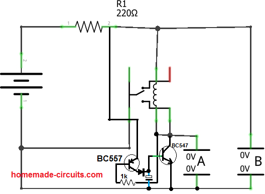
I think I got it now.
You can probably do the following modification to your existing circuit:
The base diode can be a 1N4148, and the capacitor can be a 1uF
Thank you, I will try that and get back to you.
Bob.
Thanks Sir for this article, I tried the “without push button” circuit, but it was was even on for more than 10minutes and never became deactivated ‘forever’ I don’t know why is not going delay off .
I want a without push button circuit, please help out.
Seun, you can try reducing the 1M base resistor to 100k or lower and see the effect, or you an also try reducing the value of the 1000uF to 100uF
No I have not built the circuit. I have been busy with other things. I will let you know as soon as it is built. Thanks.
Okay!
Good day Sir, please I need a circuit that when DC supply is given its relay is activated and deactivated immediately. Thanks Swag
Seun, just connect a 47uF capacitor in series with the relay coil, and a 22k resistor parallel to this capacitor, this should fulfill your requirement…
Thanks Sir, it worked, but how can I make the on and off 3secs interval for the relay push button.
Glad it worked seun, the value of the capacitor determines the ON/OFF delay time, higher values will give higher delay time and vice versa
Hello
I’ve built a muting circuit to mute audio on startup of an amplifier by grounding the outputs and then releasing the grounds once the circuit trips the relays. The problem is only one relay is activated, the other one sometimes works many seconds later or not at all.
Is there a way to post a schematic?
Hello, you can post the schematic on any free image hosting site and provide the link here, I will check it out…
Here’s a link to the image of the schematic.
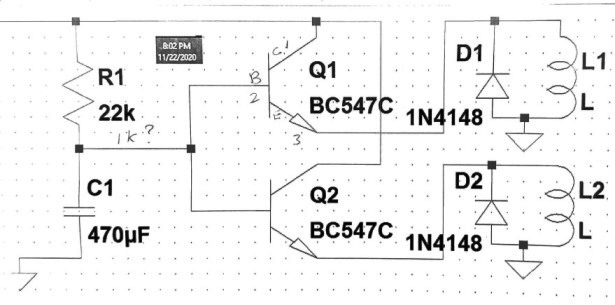
A relay should be always connected to transistor collector, not sure why you have connected them to the emitters. Anyway, in the present set up replace R1 with 10k, and add a couple of more 10ks one each in series with the bases of the two transistors, an see if that solves the issue….
Thanks for the reply.
I was following someone else’s schematic. So it’s ok with the relay coil connected to the emitter?
I have the 2 transistors on a stripboard with 2 bases on the same strip. Could i just use one 10k resistor going to both? If not I’ll have to redo the layout.
Using two separate base resistors ensures uniform sharing of the current and equal response from the transistors, if you use a single the condition may not show any improvement.
Ok so after marking those changes. I can hear the relays clicking between 7 and 10 seconds. Strange how they don’t all fire at the same time. Perhaps it’s just the relays? They’re 5v telecom replays and are brand new. I would like the delay to be 10-20 secs. How can i achieve this? Thanks for your input.
It is because the characteristics of the transistors will be always slightly different and will react differently to the relays. Additionally The relay resistances will be also never be exactly the same which may further add to the discrepancies.
I think you should go for a DPDT relay, which will enable you get a synchronized switching of both the relays. Otherwise you may consider shifting the relays on the collector sides for the same.
Thank you for the explanation.
As soon as i get some 10k resistors. I will give it a try and report back.
Sure, no problem!
An electronic device employs a timer circuit of a kind shown in figure. RC circuits are used to
create delay for alarm, motor control and timing application. The given circuit is part of building
security system. The input of the RC circuit is a 20 V and the capacitor value is 40 μF. When
the door is opened, you have a specified number of seconds to disarm the system before
alarm goes off. Determine the value of resistance required to create a delay of at least
25 sev ± 0.5 sec. The threshold voltage to activate the alarm is VC = 16V ± 0.05 V
Dennis, any SSR will require just a few mA to switch, which should not cause any loading on the driver circuit unless the supply current is too low, or the SSR itself is faulty.
You can also check if your SSR connections are correctly implemented, the (-) should connect with the ground, and the (+) should connect with the collector of the PNP transistor.
OK that’s fine, but for driving an SSR TIP127 won’t be required, you can simply use a BC557 instead, or any similar small signal PNP
That’s great Dennis. To increase the timing you just have to change the 100k resistor to 1M….the other 1M resistors shouldn’t be changed.
Additionally you must also change the BC557 base resistor to 100k each…please do these changes you should be able to get the desired delay.
If still you are not satisfied then you can try the next circuit just below the circuit being discussed.
Thanks for informing, hope you succeed with the project soon!
Dennis, in the following circuit, both are NPN because here we are looking for a delay OFF effect, not delay ON. Meaning, the relay should be ON initially then OFF after the set delay is elapsed.
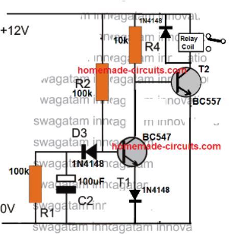
This circuit will allow you to get a more accurate control of the desire delay. You can easily get 30 seconds by adjusting the values of R2 and C2.
yes, it is wrongly printed as BC557 for the T2, which should be actually BC547
hi.
After energizing a dc voltage regulator, I want to open it a few seconds late.
how can I do that?
thank you.
which DC regulator?
MIC29302WT
try putting a 100uF parallel to R2
I am looking to build a momentary foot pedal switch in a audio application. I am using a condenser mic which requires 48V DC. I would like to build a foot pedal that allows me to use a single xlr input but has two xlr outputs. 48V “phantom power” comes from the mixer via pins 2 and 3. I need to be able to add about a 5 millisecond delay when the switch is pushed in order to keep from causing a “popping” noise. Have you ever done anything like this?
I appreciate any help you can provide.
Do you want the delay for the 48V DC input or the music input? If it’s for the 48V Dc, it can be done, but not for the music!
I have been looking at another option that may be easier. If I used a constant 48V power supply upstream of a DPDT momentary switch that would keep me from having to use the mixer 48V power. the problem is that switching the signal from one channel to the other would possible cause a popping in the sound. is there way to stop the 48V from traveling back thru the switch? From what I have found, I sound be able to short the signal for the “off” channel to pins 2 and 3. I hope this makes sense.
I will have too see the schematic drawing to understand the positions of the signals, only then I can suggest a solution. A popping sound may possibly arise due to the sudden switch ON of the 48 V DC, not the audio signal.
If you want the 48V to reach the other side slowly or exponentially, then that can be done with a transistor capacitor and the popping sound could be avoided.
Swagatam, look at the performance and mastery of the timed states, it seems they are your strong suit … I am fond of them, this delay for ignition plays in different projects, it is dynamic … hello, do not forget the washing machine type with delay of the start of the other turn … type washing machine …
great description and circuits.
I am try to make circuit in that, when we press button turn on led for some millisecond and turn off even if button is still pressed.
please help me on it.
Thank you, just replace the 33k with a 0.22uF capacitor in the first circuit, and remove the 1000uF capacitor.
Dear sir,
I required off delay adjustable timer circuit 0-1hour
Input 230v AC
Output 12v DC
With 555 or if any
Dear Kamesh,
you can try the first circuit from the following article:
https://www.homemade-circuits.com/interesting-timer-circuits-using-ic-555-explored/
Adjust R1, C1 values appropriately to get the 60 minute delay.
Hi, very interesting circuits. Can you help me to build a momentary switch activated by 220v or 12v please, after a few second??
I just need it to replicated a push button, and then Off, so disconnected.
Next 220v or 12v applied, the switch close itself again, after a few second delay, and again off.
Thanx
H, you can try the following customization
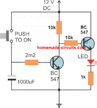
For loads other than the shown LED, must be connected beyween the positive and collector of the right side NPN….
Thx you, your site is a MUST for an electro lover!!
I will try the schematic you gave, and I read down that you also advise to try first circuit, just replace the 33k with a 0.22uF capacitor, and remove the 1000uF capacitor.
So I will give a shot to both and see which suits my needs.
Thx you very much!
Thank you, I am always glad to help!
I would like to backlight a desktop calculator with el wire and a timing circuit. Is it possible to have the LCD screen trigger the circuit, switch on the el wire device and then turn off after 1 minute of inactivity? The wire is powered by 5v usb.
You can try the following one:
The Diode shown at the collector of the transistor should be replaced with the EL lamp, cathode towards the ground side.
The EL lamp will light up when it detects the LCD screen light, and will remain ON for a minute after the LCD is turned OFF
Hi Swagatam,
Nice work you doing here, answering all the guys with patience…
I tried to find the nearest related circuit to make it easier finding a solution.
I will try to use this in my bathroom to activate a fan which I need to run immediately as soon as it sees some light and switches off after the person left the room and switched off the light.
I am thinking of replacing the diode which you told to replace with the EL lamp by a Relais which will power the Fan.
My questions are:
1. am I correct if I increase the capacity of the 470uf capacitor to increase the time for switching off?
2. R5 is a regular LDR ??
Thanks in advance..
Thank you IŞIL AYLANÇ,
If you intend to use a relay as the collector load, then you can simply connect the relay coil parallel to the existing diode, and use its contacts to switch the lamp.
You are right, increasing 470uF will increase the delay OFF time.
Alternatively you can replace Q1 with two BC557 connected in Darlington mode and then increase the 27K value to 100K for getting a higher delay OFF time
R5 is an ordinary LDR
Dear Mr Swagatam ,
Thank you so much for the above timer circuit.This is what i have been looking for.
Someone brought to me a Qlink stabilizer which couldnt enter delay to repair.I have concluded to use a timer switch to repair it by which the output wire of the stabilizer will pass through the relay of the timer circuit,to delay the stabilizer about 5 seconds.please i need the formular for the time calculation.
Should i go ahead or what do you suggest,Thanks.
Hi Patrick, do you want a delay ON circuit, meaning do you want to modify the existing relay inside the stabilizer with a delay effect of 5 seconds?
helo mr swag,
I forgot to ask where i should i tap the 12v to suply the delay circuit from the stabilizer circuit board
Hello Sir ,
No,not to modify anything in the stabilizer circuit,but to construct a different 5 seconds delay ON circuit board with its associated components and relay. I plan to pass the output of the stabilizer wire through the relay of the timer,so that when the stabilizer and the timer are powered ,the timer circuit switches ON output after 5 seconds. That is the circuit delays the switching ON of the stabilizer immediately when power ON switch is pressed.where do i tap the 12v to relay of the delay circuit. I hope i sound clearer now .Looking forward to your answer. Thank you.
So this delay is required only during the initial switch ON period… or during the entire voltage up/down fluctuations also??
Helo sir
I expect the delay circuit to energize the relay after about 5 seconds and remain on indefinitely nuntil the stabilizer is switched off again,because the stabilizer output wire passes through its 12v relay.the delay circuit having its own relay,is energized and the its relay allows the stabilizer output wire to pass through after like 5 seconds.
Patrick, I think it is just a delay ON timer circuit that you want, you can find it under the heading “Delay ON Timer Circuit Working Details”
The D1 zener can be removed and replaced with a wire link.
Adjust the values of R2/C2 appropriately for getting the 5 seconds delay
Hello Swagatam. I want you to help me with a simple diagram that has a relay without a push button. When we connect it to a 12 volt source it gives one pulse and stops working even if the circuit is not disconnected from the source.
Thank you very much.
Hello Abuesak, the solution is already given under the heading “Without using Push-button….” in the above article.
You can use the second diagram. and adjust the R2/C2 values for getting the 1 second ON time.
Dear engineers Swagatam
Please help us to get a analog circuit diagram of a Beeper.
Periode :3000 ms
– Thin beep duration 1000 ms
– Bass beep duration 2000 ms
Thank You very much for your answer.
Institute of Biophysic
March. 28.2021
Sorry Hamid, I do not have this circuit with me at this time!
I am in need a a delay on/delay off timer. Upon input contact closure I need a 1 to 2 second delay before the timer contact closes (and stays closed) and then upon the original contact opening, a delay of 3 to 5 seconds before the timer contact opens. Thoughts on how that might be accomplished?
Thanks!
You can try the following design:
Sir can you make a diagram for adjustable on and off timer. Please for saving electricity of cooler water pump.
Abhay, you can try the second concept from the following article using IC 4060:
https://www.homemade-circuits.com/how-to-make-simple-versatile-timer/
To know more about IC 4060 you an read the following article
IC 4060 Pinouts Explained
Hi prince of electronics mr swagatam, ever glad to hear from you. Please can you help me
to connect a two segement diplay on the the circuit of 5 to 20 minutes timer delay on?
I will be grateful for your support as usual. Thanks.
Thank you Kaluya, You can refer to the following article, it shows how to make a digital timer using a two segment display.
https://www.homemade-circuits.com/simple-digital-timer-circuit-with-2-digit-display/
Hi swagatam,
Can you please make 555 timer based ON time delay for 5min adjustable with 12v powering the circuit.
Actually many circuits i saw is delayed ON after pressing the push switch. But I need the circuit without using push switch. If powered the circuit, it should automatically start timer
As same like a stabilizer works.
Thank you ????
Hi Vamsi, do you want the timer output to switch ON after some delay? Normally the output becomes ON immediately when the switch is pressed and then switches OFF, so do want the opposite.
Hi swagatam
Yes. Exactly. I want the timer output to switch ON relay after some delay. But here I need the circuit without push button.
That means same just as like a telivision stabilizer.
If powered the circuit it should start timer and after 5min. delay then the relay should stay activated.
Thank you very much for the reply
Hi Vamsi, I think the following IC 555 circuit can work to provide the inverted delay ON output.
The diodes are optional, they can be ignored and removed…..
Sir,
Here why a 1k resistor used in between 12v and out / 547 transistor….?
And R3 1meg and C2 470uf both the components are for setting delay right sir…?
Thank you
Hi Vamsi,
The 1K provides the positive output after the delay is over.
yes R3 and C2 are for the time delay adjustments.
I truly appreciate this post. I have been looking all over for this! Thank goodness I found it on Bing. You have made my day! Thanks again
I am glad you found the post useful, thanks for your kind feedback!
Hi,
After days of research, i finally saw this article and its very interesting and helpful at the same time.
Being a mechanical engineer, i have not much knowledge about electronics. But i always fascinate how simple components does the trick and operates from simple to complex logics.
My intention is to build a tennis ball throwing machine.
My requirements are, once the machine turns left it should press the limit switch and in turn should stop the turning motor (M1) only for 2 seconds and the should start the motor again in order to crank the machine towards right(changing of dirrction will be done by mechanical crank and levers). And then same thing should happen again over the right side.
Also at the same time, the either limit switches should stop the supply to a proximity sensor installed at motor M2 only for 0.5 seconds and then the supply should start again as normal.
Supply would be 12V dc.
Kindly advise, thanks..
Hi, I will try to design the circuit soon, and post it as a new article. However it won’t be a simple design rather a complex one involving 3nos of IC 555 circuit
Is there an inexpensive way to set up a cascading digital data delay so that the original signal is delayed in several discrete stages? My proposal is to delay by hours to days an identical action taking place in another unit, followed by another identical unit with the same delay. The loads are LED lights, a small water pump, and a small fan. The application is in a series of planters where a computer turns on the PLC controlling full spectrum lights and simulates wind with a small fan and waters as necessary using a pump on a moisture control. I want the same action taking place in the other units by delay.
If these are simple logic levels, then it can be delayed using a 4017 IC, but if the data is a complex information such as a set of signals or frequency then it cannot be delayed by a simple method
Thank you so much for this lucid lecture. Please sir I need an ON delay timer circuit diagram whereby during delaying a blinking LED will be glowing and after delaying it switches off while the ON LED starts glowing. My DC supply is 12v. I need it for my project. Thanks.
Thanks moses, what is the range of the delay time….if it is short then a transistorized circuit can be applied, if it is much longer then an IC 4060 will be required….let me know about it!
Thanks sir The delay time is 5seconds. I need the circuit diagram for that. That blinking effect of the LED marking when the delay is on is very important for the project. And again the blinking LED should stop or switch off when the delaying has stopped and the load is now activated with ON LED now glowing. Thanks.
Hi Moses, you can try the following design:
for the blinker circuit you can try the following design:
Single Transistor LED Flasher Circuit
….T2 should be BC547, it is mistakenly shown as BC557. T1 can be any other powerful transistor such as TIP122 etc. depending on the load. The actual load can be connected between the the positive line and the collector of T1
Thanks a lot sir.I hope the blinker LED will go off as soon as the load becomes activated.
yes it will go off when the delay is over, and the load is On
Thanks a lot dear,am grateful. I think there is a natural calling dimension of what you here. You will continue to increase in wisdom as you do this. God bless you richly.
No problem Moses, God bless you too!
Good day sir. I need a similar circuit you designed for me but this time an ON delay timer circuit with blinker LED that blinks for 5seconds and then continues glowing without blinking any further as soon as the load becomes activated. God bless you.
Hi Moses, did you try the previous circuit, is it working?…..the new circuit can be designed only once the previous circuit is tested and confirmed!
Hello Chinomso, you have posted your question under the wrong article, the above article is about simple delay timer, so please post it under the relevant article, if possible I will try to help!
Thank you sir, but I don’t know the right platform for this, for this is very crucial for my inverter circuit. i have actually benefited from a lot of your posts, and I will appreciate it more if you put me through on this. Thanks again
Chinomso, please use the search box at the top of the page and type the required keyword for getting the relevant posts, and then you can select one of the relevant posts to ask your question.
Hi, I’m looking for a simple 12v timer circuit that delays turning off a relay for about 5 seconds (easily changed if longer delay needed),
ie turn a main 12v power switch on, timer circuit/relay turns on and controls another separate event, after 5 seconds, relay turns off, but main power is still on to the timer circuit powering the other equipment. Only turning off the main power switch and starting the sequence again will it reset and allow the delay time again.
I was looking at either of the “Without a Push-Button” circuits, would either of these work as above description?
Or is there something better?
thanks in advance.
Hi, you can try the 6th circuit diagram from top. This should be able to solve your query:
R2, C2 can be adjusted for getting the intended delay
thanks, with the R100K, C100uF values shown, what would the delay be?
what values would be suitable for approx 5 sec?
thanks again
Calculating would be difficult. you will have to experiment it practically and check.
Pls I need either an equivalent or another transistor to replace this b1398… I found it damage in my car stereo and we can’t find it in our local store.
You can use TIP32 as a replacement
Hi sir, pls I need delay diagram with note that will work for 8 hours and off 16 hours.
Thanks sir
Hi Zuredu, you can try the first circuit from this article:
https://www.homemade-circuits.com/how-to-make-simple-programmable-timer/
use 20 nos of parallel 1uF non-polar capacitors for C1, and use 4M7 pot for P1
Hi Swagatam. My old HVAC thermostat had separate switches for Auxiliary Heat and for Emergency Heat. When I bought a new brainy thermostat, it has regular heat and Aux heat, but no connection for emergency heat. The instructions say to simply wire the aux and emergency heat wires together. Well, that means that when aux heat kicks on, it runs both heat strips. So I was thinking…if I had a delay circuit between the aux and emer heat wires, set for, say, 6 minutes, then when aux heat kicks on, it would also energize the timer and not kick on emergency heat unless aux heat couldn’t raise room temperature in 6 minutes. Voltage is 24VAC. Heat strip relay coil is 24VAC 1 amp. So circuit would have 24VAC IN, and delayed (+-6 minutes) 24VAC 1 amp OUT. Timer would reset when 24VAC input went to 0 (thermostat kicked off). Can you help me? Thanks.
Hi Jim, you can try the design which is given under the heading: “Delay ON Timer Circuit Working Details”
You will have to disconnect the R2 upper end from the supply line and connect it with the supply voltage that would appear when the the AUX heater kick in.
However, the input to R2 must be DC and not AC from the AUX heater.
Thanks. The 24VAC aux voltage is only present when the Aux line gets energized by the thermostat. So are you saying I need two voltage inputs…one constant 12VDC source for R4/T2, and one switched 12VDC source for R2? Can’t I take the 24VAC from the aux line, rectify it, drop to 12VDC, and use that as my input voltage for the circuit? Why do I need two voltage sources?
Can the circuit handle 24 V or do I need to step the voltage down to 12 V?
–Jim
OK, in that case you can rectify the 24V AC to DC and feed it across the supply lines of the delay timer. For this you don’t have to change anything in the circuit, no need of disconnecting the R2. However, if 24V DC is used then the relay will also need to be a 24V. Alternatively the 24V DC could be stepped down to 12V through a 7812 IC for using with a 12V relay.
I like your delay timer circuit without a pushbutton. I think this would be perfect for a project that I am working on. However, in order for me to utilize this design, it need to be powered by a 24 volt DC, 1 amp power source. Can this be modified to work on the above power requirements? \And if so, how?
Yes, the same circuit can be used with a 24V supply also, without any modifications.
Congrats for this page… Swagatam
My problem is as follow, I have 5 volts and 12 volts at disposal (both are available if needed), I can use either transistor or 555 timer.
Only one push button. I Press one time the relay switch ON. I press another time: one TTL output (transistor ?) immediately advise a microcontroler, X seconds after (around 30 secs but may be less) the relay switch OFF. and so on
Any help will be fine
Thanks and Regards
Thank you Noxam, is the relay supposed to latch when the push button is pressed for the first time. Should the 30 second delay happen only after the second press??
Dear Sir,
Initial state
1) Press button relay switch ON
2) Press Button -> immediate advise MCU and relay switch OFF after 30 seconds
3) Go to initial state
Thanks alot
Yes I have understood, but what happens if the button is not pressed for the second time? does the relay stay ON permanently? When should the delay start, after the second button press or the first button press?
Yes the relay stay ON permanently, the only way to switch OFF is to press again the second time.
The delay start after the second press. May be I was not clear but there is only one push button here.
1) Press BUTTON relay switch ON forever
2) Press BUTTON -> immediate advise MCU and start delay to switch OFF relay (30 seconds)
3) 30 sec
4) Relay is OFF
5) Go to initial state
Best Regard
Thanks, I am working on it!
Great it is not an easy case
Thank you
Yes it was not easy but I managed to do it…I hope it will work.
You can find the complete design in the below shown diagram:
Pin#4 can be used for triggering the microcontroller
Great I will immediately try a prototype.
Which Components determine the 30 secs time ?
Regards
Sure!
The 100K and the 1000uF at the base of BC517 determine the delay output….but I have selected them randomly, they will need to be adjusted with trial and error.
Really Excellent work
Good day Sir,
I have the following problem, hope you can help me with the circuit. I need to get a push-button effect when apply 220v current to the circuit, and another push-button effect when I disconnect the 220v.
Thank you very much for your support.
Hi George, you can try the following concept:
Please enlarge the image, since it is too small to see.
Thanks for your efforts on this page! I haven’t seen what looks like a solution to my case, but I may have missed something. If I may, additional information on the behavior and application of each of your examples would be helpful. The descriptions are rather terse.
There are many solar powered lights on the market, and many of them have a dusk-to-dawn feature using a photovoltaic cell (whether the battery charge lasts that long is another matter). What I would like is to switch off the power a configurable length of time after the circuit is activated. For example, I’d like the light to run for one hour after the photovoltaic sensor switches on. Thus, I need a timer that operates from the moment power is applied and does so using the low power from a battery.
I imagine using a relay to control the power delivered to the light(s), but the relay control requires a timer that activates the relay initially and deactivates it after the delay (or vice versa, depending on the relay). The result will be used to illuminate a chicken coop at dusk long enough for the chickens, which have very poor night vision, to make their way inside without my having to switch lights on and off at the right time.
Thanks for your help!
Sure, that is possible using a IC 4060 circuit as described in the following article:
https://www.homemade-circuits.com/how-to-make-simple-versatile-timer/
You can try the relay based circuit, with the following modifications:
Connect the output from the dawn to dusk circuit to pin#12 of the above circuit through a 1N4148 diode.
Make sure the output from the dawn to dusk circuit is high during daytime, and becomes low during dusk or in the absence of ambient light.
Alternatively you can simply connect an LDR across the positive line and the pin#12 of the above IC 4060 circuit an get the very same results.
I want to make a delay push circuit in which Led should stays ON as long as push again for few seconds to turn it off.
what you are asking is a flip flop circuit, not a delay circuit:
https://www.homemade-circuits.com/build-these-simple-flip-flop-circuits/
Dear Swagatam
Appreciate you can please assist, your guidance, thanks!!!. I want to charge a capacitor e.g. 16 V, 8 F from a car alternator and discharge the capacitor into a battery bank that is separate, not connected with the alternator. I want to, after the capacitor is charged up, electronically disconnect the alternator charging circuit from the capacitor and a few seconds thereafter electronically connect a seperate discharging circuit with the capacitor, discharging the capacitor into the battery bank (battery bank and alternator not connected). It is important that at no instance the alternator capacitor charging circiut and the capacitor discharging circuit into the battery bank will not make contact, not be connected. in contact. My question how to design the electronic alternator capacitor charging on off and the electronic battery capacitor discharging on of circuits. Apologise if this is off topic. Thanks, Regards
Thank you Andre, However this seems to be totally off-topic. If possible please post it under the following article, I will try to help:
https://www.homemade-circuits.com/multiple-battery-charger-using-dump-capacitor/
What is the 2m2 resistance value shown in the circuits above?
2M2 = 2.2 Meg ohms
Thanks.
In the schematic where it says: “The following circuit shows how the associated push button may be rendered inactive as soon as it’s pressed and while the delay timer is in the activated state.”
Where is the load output pins?
[img] [/img]
The load output is between BC557 collector and ground.
In the schematic where it says: “The following circuit shows how the associated push button may be rendered inactive as soon as it’s pressed and while the delay timer is in the activated state.” How many seconds of delay we are talking about, I need about 5 seconds delay, Can a potentiometer be added somewhere to make time delay adjustments?
I don’t remember the timing that can be achieved from a 2m2 resistor and a 1000uF capacitor. You will have to confirm it practically. You can replace the 2m2 with a 2m2 pot and a series 1K resistor. If a 2m2 pot is not available you can try a 1M instead. Remember to put a 1K resistor in series with the pot.
I also have a concern about the load resistance, I got a solenoid of 9.4 ohms with a tested 1.4 amps under 12V, do you think this load can be handled by the circuit?
If the load resistance is high, then the BC557 can be replaced with TIP127 or any similar transistor.
The load resistance is low (9.4 ohms pull solenoid), I was told by a forum member at eevblog that it will overload the T3 base even when a relay is used to energize the load.
T3 refers to the BC557 next to the diode.
You can use 10K resistor for the base of BC557 if you are using a relay. If you want to use the load directly at the collector of the transistor then you will have to calculate the base resistor, although it can be also estimated through some practical experimentation..
Hi Swagatam, Im working on a ac led strip my aim is to achieve the maximum efficiency..that means I want this circuit(AC strip) to work till 300v I have also designed a circuit but there is no way that i can share it with you… How can i contact you? I hope you get my mail when i post this comment… Hope you’ll reply..
Hi Manav, you can upload it to any free image hosting site online and provide the link to me here. Make sure to remove https while providing the link.
And please post it under an LED driver article, because the above article is related to timers not to LEDs.
Hello,
Please, Can you explain how to use the rotary switch on timer to set the time interval for a semiconductor timer such as AB 700-RTC11200U1. Practical examples would be appreciated.
Thank you.
Hi, sorry I have never used the mentioned unit, so have no idea about it.
Hi!
I am currently working on a device that controls two 6VDC pumps, where the pumps are triggered with an IR sensor. The sensor will start the first pump and run for 1-2s, then with a time delay of 2-3s the second pump should start, while the first one has already stopped.
Do you have any tips how I could accomplish my goal? I was thinking of using capacitors and transistors for the time delay, but I’m not sure how I can make sure that the first pump stops before the second pump starts.
Thanks in advance!
Hi, How is the sensor supposed to start the timer, is it through a momentary pulse? And what happens after the second pump stops?
Yes, the sensor will cause a short pulse. After the second pump stops, the system should become idle and wait for a new trigger of the sensor – then the pumps should be activated again.
This device should work similar to an automatic disinfectant dispenser. I hope my description is understandable!
OK, understood, and how is the second pump triggered, is it through a second subsequent pulse from the sensor? And a 3rd pulse for resetting the circuit?
The second pump is not separatly triggered, it should just start after the first one has stopped. It would be great if there is no need for a pulse to reset the circuit, but if thats not possible then I will use a second pulse for now.
It looks difficult without a manual triggering for the second pump. However it can be perhaps accomplished using a 4017 IC along with 4069IC and a couple of transistors. The sequence will initiate through the sensor’s negative edge signal, meaning, when the sensor switches ON and OFF then the sequence will be triggered.
Hello Swagatam, I am trying to design a circuit similar to an automatic nightlight. The difference being that it needs to be off when the room lights are on, then switch on for about 10 seconds only when the lights go out, then switch off fully until the room lights come back on without doing a fade out. The other requirement is the light sensor section be powered by a solar battery and not draw off of the LED batteries, or some other type of light sensor that draws a miniscule amount of current (photo transistor?) when no light is detected. I figure there will be a capacitor in the sensor section, but I can’t figure out how to charge it without the LED’s switching on, or keeping the LED’s off when the capacitor becomes fully charged and as long as the room lights are on. I was planning on using a 2N2222 NPN transistor for the switch. The lights are 8 LED’s wired in parallel. The batteries will supply 4.5 volts. I really appreciate your help on this.
Hello T.C., you can probably try the following circuit for the mentioned application: I have used IC 555 monostable since a fade out effect is not acceptable on the LEDs. R1 and R5 both can be 10K resistors.
Thank you for your reply. The circuit you have provided is very informative, but not quite what I need. The voltage requirements in the schematic is 5-12 volts. The maximum voltage available for my project is 4.5 volts, reducing to the minimum required to light the LED’s as the batteries drain. Could you please explain the function of the 2 NPN transistors in the input circuit? If I were to use the CMOS version of the 555 (to reduce voltage requirements and current draw) the solar cell should be enough to trigger it, or am I missing something here?
Yes CMOS version of IC 555 can be used which will work with 4.5 V easily. The BC547 connected with the solar cell ensures that while light is present it remains turned ON, and keeps the other BC547 transistor turned OFF. As soon as light is switched OFF, the left side BC547 associated with the solar cell turns off which turns ON the right side BC547, which in turn causes the pin#2 of the IC 555 to be grounded, initiating the timer action. Pin#3 now turns ON for sometime turning ON the TIP122 and the LEDs until the time elapses and the systems is completely switched OFF, until the external lights are turned ON again. The solar cell is enough to trigger the BC547 since it only required 0.6 V for the process.
I pretty much understand now, but still have one question. With a 10k between Vcc and the second transistor base, and a 2.2k going to ground, wouldn’t the greater negative potential prevent the second transistor from ever being able to switch on?
The BC547 requires just 0.6V base voltage to switch ON, which can be easily acquired from the shown resistor set up, it is fine according to me.
Hi
I am a member of a model railway club and for signalling we use inductive sensors in the rails. The sensors are npn i.e. when the wheel of an engine passes the sensor grounds a relay coil, the other end being connected to +12v. I am looking for a circuit to delay the on time of the relay for say 1sec. with an output from the sensor going from 12v to zero to activate.
All the above use circuits use plus volts to trigger.
Hi,
You will need to do the following modifications to your NPN transistor for getting the 1 sec or more delay:
For 1 sec delay the value of the capacitor could be around 100uF, however the 10K might need to be increased to 47K
Hi
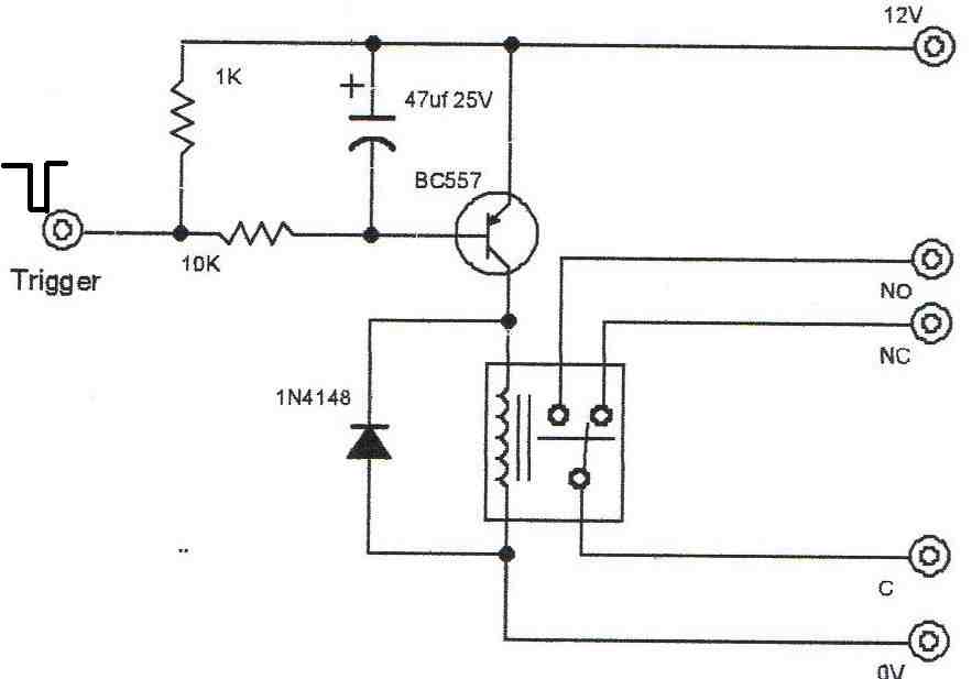
This is as far as we have got, looking to hold the relay on for 0.5sec. This is by trial and error, we cannot measure the time on, what do you think.
Hi, It Looks good to me,
You can use a Darlington transistor and increase the resistor value to 100K, for getting higher delays.
Thanks, I may follow up that idea.
0.5s on and 0.5s off circuit?
you can use the following circuit, just press calculate
https://www.homemade-circuits.com/transistor-astable-multivibrator-amv-calculator/
Hello.
I appreciate your hard work.
I’m going to construct the following circuit.
I am going to drive a 12V relay using a 12V power supply.
If you press the button, the relay turns on after 0.5s
If you release the button, the relay will be turned off after 0.5s.
I need your help.
Thank you.
You can try the second circuit from top. You will have to disconnect the capacitor from its existing position and shift it across the base/emitter of BC547.
The 2m2 could be reduced to 100K, and the 1000uF which is now connected across base/emitter of BC547 can be reduced to 33uF/25V….the values will need to be experimented.
The LED/resistor will need to be replaced with the relay….the relay coil must have a freewheeling 1N4007 diode.
Hello.
Thank you for your help.
I want to make another request to you.
I’m using a 220v light.
I want to BLINK by installing LED on the light switch. But the light switch has only one phase out of 220v voltage.
Will it be possible?
I look forward to hearing from you.
You will need phase and neutral both for flashing the LED, only phase will not work.
it doesn’t work.
I am still trying to drive a 12V relay using a 12V power supply.
Pressing the button will illuminate the relay 0.5 seconds later
. Release the button and the relay will turn off after 0.5 seconds.
I need your help.
Try the following set up. But the time will not be exactly 0.5 second, you will have to adjust the two capacitors to get the desired timings.
Hello.
Thank you for your reply.
I will go to the office on Friday and test it and contact you again.
I hope you have a great week.
Thank you.
Sure, no problem!
Hi.
I did a test in the office.
But it still doesn’t work.
Pressing the switch also shortens the + and -.
So I removed the – associated with the switch.
Also, if you change the first 10k to 100k, it turns on after 0.5 seconds. But off works immediately.
Which circuit operates exactly 0.5 seconds on and 0.5 seconds off?
Thank you for your help.
Sorry, yes there was short circuit in the diagram, I have removed it now. However I cannot find any other easy circuit which would give you exact 0.5V second ON/OFF. You will have to experiment with this circuit only….you can try adding a 470uF right across the relay coil and see if that helps.
The following diagram is the last option I can see. You can experiment with the capacitor C for adjusting the relay ON/OFF timing:
Oh, thank you.
Press Switch -> 0.5 second delay on
Switch off -> 0.5 second delay off
What is a simple circuit?
The time doesn’t have to be accurate.
Thank you.
The transistor circuit which I gave you is the simplest one. You can try adding a 470uF across the relay coil, or try adding a 100uF directly across the base/emitter of the transistor and see that gives you the required results.
Dear sir,
Recently I started reading your blog. I became regular. Nice explanations. Kudo to you.
BTW, I have a requirment. There is intermittent DC voltage available in case of a fault. Say, 12V is “on for 2 sec and off for next two secs” and the cycle repeats, till the fault is cleared. I want to use this intermittent DC voltage to switch on a relay irrespective of on/off state of the input. ie once the DC voltage starts available, the relay should get energised until this intermittent supply is totally off which will happen on clearance of fault.
Please suggest a suitable scheme. Thanks in advance.
Thank you S Lakshminarayan, your application is quite easy to implement. You can use the first circuit from top, remove the push button, connect the intermittent signal across the capacitor through a diode 1N4148, replace the LED with a relay (with a freewheeling diode connected across the coil). You will also need to replace the 1000uF capacitor with a lower value capacitor such as a 47uF/25V. Let me know if you have any further questions.
Dear Mr Majumder,
Thanks a lot for your valuable suggestion. I will try and let you know the result in a day or two.
With regards.
You are welcome S Laxminarayan, let me know if you have any problems.
Dear sir,
I have built the circuit with bd139 and found working fine. Thanks a lot.
I have one more requirement. I have a built plasma flashback astable driver with 555. The frequency is about 25 kHz with duty cycle of 59%. Output of 555 goes to small signal push pull transistors, driving a MOSFET with very low RDS. Though the circuit is working fine (good plasma arc is produced with moderate heating of MOSFET), I am having 555 failure after some time, due to fly back voltage, though the output current of 555 is limited to 100 milliampere. The entire circuit operates on 12v DC. Current is about 2A on arcing. Transformer is wound by me with ferrite cores. No snubber or fast recovery diode across primary of transformer.
Please suggest a suitable protection circuit so as to protect 555 IC from failure.
Regards.
Dear S Lakshminarayan, the problem could be happening due to the reverse voltage spikes from the flyback coil. You can try putting a few extra components around the supply pins of the IC 555, as shown in the following diagram, and see if that helps. You can additionally put a reverse 1N5402 diode across the drain/source pins of the MOSFET
I have a module for use as a watel level alarm. When the higher level is reached it gives an alarm, so that we can shut down the water flow (manually). The problem is that the alarm is ON Continously until the water level goes down. I need the alarm to be ON for maybe 2 minutes and then trigger OFF even when the probes are in conduction. Putting a switch in output is easiest solution, but then we have to switch ON/OFF the switch every time, which can be forgetful. Please suggest some design for this. If needed I can send a basic diagram of components used but it has a covered module which I have not broken into. The probes use AC for water level detection.
Thanks.
I can suggest a simple circuit to solve your problem but the circuit will not use an AC based probes, will this be OK for you?
Sir, i need to 5v delay on circuit with a 5v relay, is there a circuit diagram available
Saroop, a delay ON circuit is already given in the above article. Please see it under the heading “Delay ON Timer Circuit Working Details”
You can use 5V supply and a 5V relay in that circuit
Thank you sir, can you provide the time for delay on circuit as per the specifications of components provided in that section
Swaroop, Only R2 and C2 determine the output delay, you will have to test it practically to check how much delay you get with the specified values, and then you can adjust their values to get your own desired delay ON time.
Hello sir,I’m intending on building one of your sg3525 inverter circuit but the problem is that I will need a timer circuit so that when the battery reaches around 11.5v it switches on for some seconds and eventually shuts off so that I can get an indicator of low battery before it reaches 11v and switches off the inverter. And I would like the indicator to be a buzzer . Pls sir I would be great full concerning any positive response
Hello Melvis, you can attach the following circuit with your battery:
You will have to adjust the 10K preset such that 741 IC output just becomes high at 11.5V battery voltage
I want to construct a time delay relay circuit for an amateur radio tube type amplifier, The TD relay will be used to control the delay time in turning off the cooling fan – which should be approximately 3 minutes after turning of the AC power rocker switch for the amplifier. The fan is a 120VAC, which obtains its operating voltage from a tap on the main transformer. The amplifier power is supply is wired for 230VAC. When the rocker switch is turned OFF, the power to the amplifier is OFF. However, there is STILL 230VAC being supplied to the INPUT side of the rocker switch. This is my dilemma. I still have 230 VAC available on the input side of the rocker switch. How do I supply 120VAC to keep the fan operational for 3 minutes, with only 230VAC available on the input side of the rocker switch?
We will have use a separate capacitive power supply for operating the timer circuit, with a triac. The fan will be powered through the triac. The timer circuit will get the switching voltage from the rocker switch. Once the rocker switch is turned OFF, the timer circuit will keep the fan powered ON through the charge stored inside a timing capacitor. Once the charge inside the capacitor is exhausted the timer will switch OFF the fan.
yes, the 120V to the fan must be continuously operational. If this voltage is switched OFF then I am afraid the fan will not work.
Can you provide me circuit sketch, with component values, to make this circuit? Much appreciated.
So, the fan will draw its power, continuously, from the TD circuit? That had not occurred to me. But it is quite logical.
Regards
Yes the fan must have a continuous access from the 120V source. TD will provide the switching voltage for the triac. No relay is used here.

Here’s the proposed diagram for you:
Hi Swagatam,
Can your time delay on circuit be adjusted for 60 sec’s delay before turning on the relay? I also need to use the circuit in a 28vdc system it looks like the transistors are capable of 28vdc. Also how critical is the 3v zener on the emitter of T1 is it fully required?
Hi Bill,
you can create a 60 second delay by suitably adjusting the values of R2/C2 components. The BC547/557 can handle upto 45V, so 28V looks fine.
3V is introduced to easily extend the delay even while R2 C2 are relatively smaller in value. With 3V zener attached the base cannot activate until the voltage across C2 has comfortably reached above 3V which takes more time, therefore the delay is longer. Without the zener the base voltage would only require 0.6V to activate which can reach much sooner across the capacitor C2.
Thanks for the quick response I may need the Zener tried using the circuit without the Zener and could not achieve slow delays. Tried different values for R2, C2 without much success will try different Zener values as well to see what happens.
Bill
You are welcome! The zener is not the crucial element, R2 and C2 are crucial, and they should definitely cause the delay time to change significantly.
????????♂️Fantastic site ???? i wonder if you can help me? I am building a model rc submarine reading your site i thought placing a timer on servo controlling dive it would reset the vanes to vertical once again the delay not worked out yet but could you help? Take care stay safe and well????♂️????
Glad you liked the site! Can you please explain the specifications of the timer, if possible I will try to help!
????????♂️ thank you ???? the needs run from receiver to two servos, that dips and raises the diving vanes for settable ( secs ) to control depth of 2.4ghz antenna after which the vanes will return to horizontal level then rest ready for the next manouvre? Not being to knowledgeable with certain circuits ???? ????the smaller the better.could you make board? Thank you,if my autistic grandson had his way he’d have it fly!!????? Probably next project ????????????
I appreciate your explanation, however I am sorry, it can be difficult for me to understand the working of your system. I only need the details of the timer, how the timer needs to function? Is it a delay OFF timer or delay ON timer? How much delay period is it supposed to produce?
????????♂️Ok thank you, the power is 12v dc,the timer is off until receiver tells the timer to allow the servo to operate the pushrod for manual adjustable time ?it being manual to adjust so the rate of descent the alloted time after which the timer will return the vanes to horizontal position ready to be used to raise the sub????? taken on a challenge haha i am no captain Nemo ????♂️ i have no other means to explain ???? for my grandson i want it to be as easy as pos for his motor skills so i thank you kindly for your time and patience if it can not be done ???? take care stay safe and well ????♂️????
No problem! I guess you are looking for a delay OFF timer. I can suggest you the following design, however I won’t be able to suggest about the mechanical integrations.
In the timer circuit below, when a trigger or a pulse is sent to the base of the BC547 transistor, the pin#3 output of the IC 555 becomes high with a 12V output. This 12V output at pin#3 remains ON for a short duration of time and then it switches OFF. This short duration depends on the adjustment of the 1M pot and the value of the 1000uf capacitor. Both can be altered for getting different output delays at pin#3 of the IC. A relay can be connected across pin#3 and ground for the necessary integrations with the mechanical systems and the relevant operations.
????????♂️ wow!! thank you very much ???????? ???? .is there a board for this circuit? Thank you take care stay safe and well ????♂️????
You are most welcome, however unfortunately there is no PCB for this design, you may have to construct it over strip-board or a vero-board
????????♂️ THANK YOU SO MUCH ???? FOR ALL YOUR HELP ???? TAKE CARE STAY SAFE AND WELL ????♂️????
Hi Swagatam,
I have a circuit using the very small delay chip c-005. This chip works on 2-5v. If you ground its trigger, it supplies a negative output for a delayed time adjusted with a resistor. I have connected a 10k resistor between the output of the c-005 and the base of a bc807 smd transistor. I have also connected a 10k resistor from the positive voltage of 5v to the base of the bc807 transistor. This circuit has worked for me on several projects. This new circuit uses 9v so I installed an ams1117 regulator to reduce the supply to 5v for the c-005 delay chip. So, the bc807 transistor emitter has 9v and the base has 5v which can be grounded by the c-005. Grounding the base of the bc807 transistor is supposed to turn the transistor on. My problem is the transistor is always on, no matter what the output from the c-005 delay. Is the 9v on the emitter of the transistor causing the problem? Do I need to supply 9v to the base of the bc807 transistor?
Hi Norman,
yes it is due to the 9V supplied at the emitter and 5V available from the C-005 IC. Since the 5V is lower than 9V, it is unable to block the 9V from the BC807 emitter. Meaning the BC807 is always getting 5 – 9 = -4V which is sufficient to keep it switched ON all the time.
To rectify this issue, both the voltages, at BC807 emitter and at the output of the C-005 must be equal.
Hi Swagatam,
Thanks so much for your quick response. You are the best!!!
Thanks Norman, I am glad to help!
Hi Swagatam, thanks for sharing your knowledge.
I wonder if does exist simple one component delay timer.
I need to delay 12V DC rail for 7-15s. It may be fixed, preferably adjustable.
I have seen various schematics for popular IC 555 timer – is it possible to do it simple with one component, please?
Is it possible to do it with something like resistor or capacitor?
Thanks David,
To control the supply rail delay you will need some kind of control device which could be a transistor at the least. The resistor and capacitor timing components will control this transistor for implementing the delay.
If you use only an RC, the delay will not be sharp, it will rise gradually until the full voltage is reached. Moreover the series resistor will not allow the desired high current on the supply rail. So it doesn’t appear to be a feasible option.
Hi!
I’m a beginner electronics enthusiast. been trying to build a blinking LED Circuit with a Relay and a capacitor. The capacitor is supposed to introduce a time delay so the LED could blink but it doesn’t seem to be working so. I am terribly confused. Please help! ????
Hi,
why would you need a relay for blinking an LED? You can simply use a transistor/capacitor circuit to blink an LED?
Show me the name of the
component that can be used to make 4 minutes delay 4minutes delay
You can try the following design:
Adjustable Timer Circuit Using IC 555
Good day Swagatam,
Thank you for readily sharing your expertise, I appreciate you!
We are having many power cuts due to load shedding.
When the power comes back there is often damage due to voltage spikes and fluctuations.
I would like to switch my mains power on 10 seconds after the mains power comes back to ensure that the voltage has settled down, stabilized. (Yes, it can take this long here!)
I want a delay circuit that does not need to be energized by a switch, I want the delay to start automatically when the mains power comes back.
I only need the delay circuit, the mains switching part is taken care of already.
I would appreciate you kind assistance, my efforts so far with 555 timers has not worked reliably.
Andre Jordaan
Hello Andre,
You can try implementing the following delay ON circuit concept:
Let me know if you have any further doubts or questions?
Good day Swagatam,
Thank you for your prompt response (impressive!) and yes, the circuit works well.
Best,
Andre
No problem Andre! Glad the circuit worked!
Is it possible to create a delay circuit that trips if the delay is very short, but does not trip if the delay is long? For instance, if the delay is anything less than 2/10ths of a second, it trips. But if the delay is any longer, it doesn’t.
Sorry, it looks difficult, not sure how this can be implemented practically.
Good day Swagatam, thank you so much for teaching everyone so much.
Greetings from Brazil.
I’m trying to create a circuit to work with a 18650 battery between 3.3V and 4.2V that after a brief press of a push button, turn on a relay for between 30 and 60 seconds, after that turn off the relay. But it can no longer be triggered by the button, only if the circuit is turned off that it could be reset. Could you be so kind as to suggest a schematic?
Thank you so much in advance.
Thank you Macelo, you can try the following design, it looks close to what you are looking for:
However I could not correctly understand what you meant by: “…..But it can no longer be triggered by the button, only if the circuit is turned off that it could be reset”
Hi, thanks for your quick reply. I meant that the circuit can only be triggered by the push button once. So after activation and consequent deactivation of the relay after the given time, the push button will no longer be able to activate the relay. And this cycle will only work again when the entire circuit is turned off and on again. It would be some kind of circuit that only works once and then has to be turned off to become operational again.
Sorry for my poor english. Thank you.
OK, got it. In that case you can try the following 555 based design:
However make sure to use a CMOS version of the 555, such as a 7555 IC so that it can work optimally right from 3 V onward.
Thanks Swagatam, I will test your circuit. All the best.
No problem, wish you all the best!
Hi Swagatam,
I tested the circuit you indicated above.
I did a simulation in Multisim, it happens that the SCR, after pressing the button, leaves the trigger in low voltage. I think it should just give a pulse on low, to trigger the 555 and then lock on high so that the button only works on the first press. In this way, the circuit is permanently activated, as if the button was always pressed. Do you have any suggestions? Thank you again.
Hi Marcelo,
Even if pin#2 is permanently grounded by the SCR, the output at pin#3 will produce only a momentary delay pulse.
If you don’t want pin#2 to be permanently grounded, you can put a 0.22uF capacitor between pin#2 and the SCR anode.
Also remember to put a 10K resistor between the positive supply line and the pin#2 of the IC.
IT WORKED! Thank you again. Your work and your promptness are exemplary.
Great! Glad it worked!
Hello Sir, I want to make a Delay ON Timer Circuit operating with 5 volts. Can you please design a schematic for me?
Best regards,
Hello Ajaira, a delay ON timer circuit is given in the above article. You can use it with a 5V supply also, just make sure to change the 12V relay with a 5V one.
Thank you so much for your reply. I want to know one thing if I want to get 0.16 volt output, what will be the value of the resistor?
If your supply is 5V, then the delay ON output will be also 5V, 0.16 V cannot be obtained in this design.
Thanks for your reply. Is there any system to drop the output voltage from 5 to 0.16 or 1 volt? If yes please explain. I want to design a security module with an IR sensor for my car garage.
It can be dropped using resistors if a low current output is acceptable. For higher current you can use a buck converter to drop 5V to 1V. But I do not have this type low voltage buck converter circuit with me right now.
Thank you so much. Hope I’ll ask more questions about electronics in the future.
Sure, not a problem at all!
Good afternoon my friend Swagatam!
Unfortunately, I severely broke my leg and spent a long time in the hospital. Therefore, I could not proceed with the manufacture of the circuit that you kindly suggested. (https://www.homemade-circuits.com/simple-touch-sensor-switch-circuit/#comment-133997)
This circuit needs thyristors, but I don’t have them and I can’t go to the store yet. But I can already sit on a chair!
But I have another request for you.
I thought about making an alarm for the open door of the refrigerator. I want to use a magnet and a reed switch as a sensor. When the door is opened, the reed switch closes and connects power to the circuit. The timer waits for 30-40 seconds, after which the beep sounds, indicating that the door is still open.
If after that the door is closed, then the reed switch opens with the help of a magnet, the power supply to the circuit is interrupted, the signal stops.
I want to power the circuit from a 1.5 volt battery. I would like to increase the voltage to 3 volts using the HH004F chip. Is it possible?
Can you suggest me such a scheme?
Respectfully,
Jorge
I am sorry to hear that friend. I hope you will recover soon.
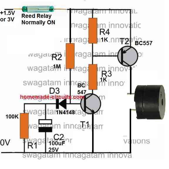
For the fridge open delay ON buzzer circuit, you can try the following concept:
Let me know if you have any further doubts!
Thank you! Some questions…
What is the working principle of this scheme? What is the delay time? Regulated by R1 and C2?
When power is switched ON through the relay, the capacitor C2 is charged via R2. While C2 charges the T1 base is inhibited from the required 0.6V biasing voltage. This keeps T1 switched OFF and with T1 switched OFF T2 also remains switched OFF. After the intended delay when C2 charges fully, D3 gets reversed biased and turns off, which allows a 0.6V to develop at the base of T1 switching it ON. When T1 switches ON, T2 also switches ON, turning ON the load.
R2 and C2 are responsible for the delay timing.
There should be a 1N4148 diode in series with the emitter of T1 to balance out D3, which is accidentally not shown in the diagram.
Good afternoon my friend Swagatam!
I made a circuit from the link:
Everything works, but only from 3 volts. If the voltage is reduced to 2.4 volts, the circuit stops working.
I changed C2 and R2 so that the signal is delayed by 30-40 seconds. I do not specifically publish the modified data of these components, since I think that a lot depends on the gain of the transistors.
There is a question: what can be done to make the circuit work from 1.5 volts?
Hi Jorge,
You can try doing a few modifications in the existing design and see if that helps.
Reduce R2 to 330K or lower and increase C2 to a higher value until the combination provides the required 30 seconds delay.
Reduce the value of R3 to 100 ohms.
Let me know if the above allows the circuit to work with 1.5 V supply.
Hi my friend Swagatam!
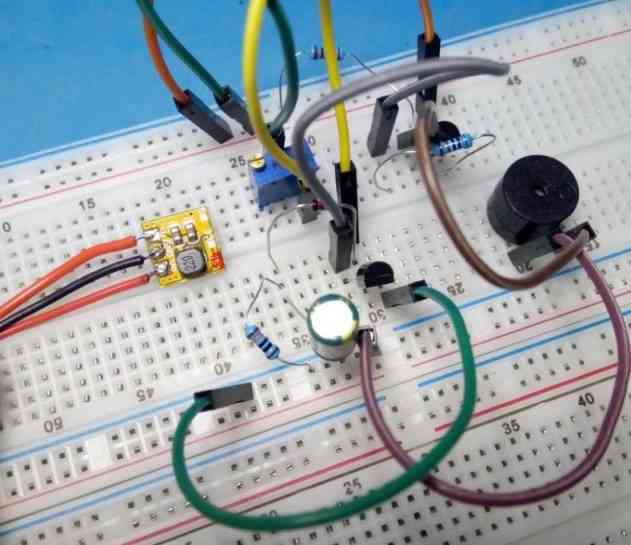
I changed the values of the resistor R2 to 300k, and the capacitor to 330uF. Thus, I achieved a signal delay of up to 30 seconds. But changing the value of the resistor R3 did nothing. The minimum voltage required for the circuit to work is 2.4 volts.
I solved this problem by using a mini boost module from 1.5v to 3v. Now everything works as it should.
If you are interested, you can see photo of the module and layout here:
Respectfully,
Jorge
That is great my friend Jorge!
Reducing R3 value was supposed to make the PNP more sensitive and respond to lower base voltages.
But no problems, I am glad you could finally make the circuit to work with 1.5 V using a boost converter circuit.
Thank your for updating and keep up the good work!
Thanks for these so simple, though efficient, working circuitries. Great Swagatam !!!
I wish to trigger the mains timer with sound (clap or any), together with the pushbutton : do I just add a microphone in parallel with the pushbutton ? Does a MOSFET improve anything ?
Thank you Ambroise, Glad you liked it!
If you want to activate the delay OFF timer with a MIC then you may have to build the design discussed in the following article:
https://www.homemade-circuits.com/simplest-sound-activated-relay-switch/
If you have a heavy DC load then you can eliminate the relay and replace the PNP transistor with a MOSFET. The referred diagram is enclosed in the above link.
Great work , I needed help on, how to do the manual calculations, for the *With push button Delay timer*, circuit
Thank you, unfortunately I do not have the formula for calculating the RC time constants.
Hi Swagatam.
I’ve looking through google & ebay thinking that what I’m looking for should be easy to buy made but not turning out so easy. There are a lot of relays that delay power on, or turn power off after a set time, but the supply power needs to be on. What I’m after is a device that once my ignition is turned off, a relay stays open for a set amount of time so that I can hook one up to my electric windows & another to the cooling fan under my intercooler.
I did buy one off ebay & thought maybe the cap on it & adjustable pot would be enough to hold the relay open & direct power to the relay would stay on the load for a few seconds for windows, minutes for fan.
Cheers
Dale
Hi Dale,
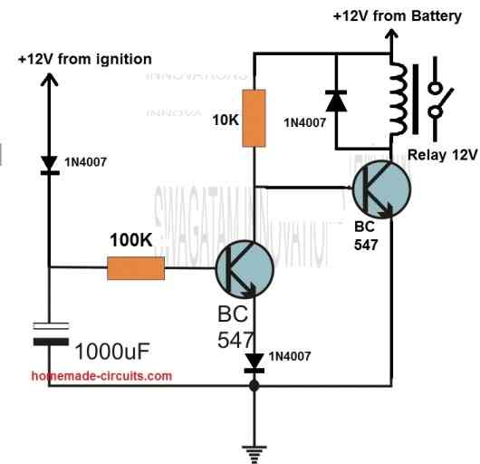
I think you should try the following circuit, it might be exactly what your are looking for.
Hi Mr Swagatam
Re: Dumbwaiter startup problem.
This is some Chinese unit installed by some previous owner which has no manufacture ID and no papers or circuit information.
Each of the two floor levers have a power on/off switch and an up and down push buttons that light up just after the power is turned on.
The 220 V AC geared motor is controlled via a frequency Voltage converter and triggered through a mini plc card which gets its 24V power through the FVC.
If we push the required up or down button, when the buttons light up, too quickly the system fails and we then need to reset, by turning the power off and on again, and then wait for 2 to 3 seconds before we press the required button after it lights up, before the unit works correctly.
We concluded that the FVC, although it outputs 24v to the plc and the button led power, the other part of its function circuit is slower, which is the delay factor.
Other then introducing a time delay in the plc to delay the start up, which we have no information on, we would like to introduce a delay to the 24V power outlet from the FVC to the PLC, of 3 seconds in the simplest, cheapest, reliable way.
Do you have a simply circuit for me please.
Hi Joseph,
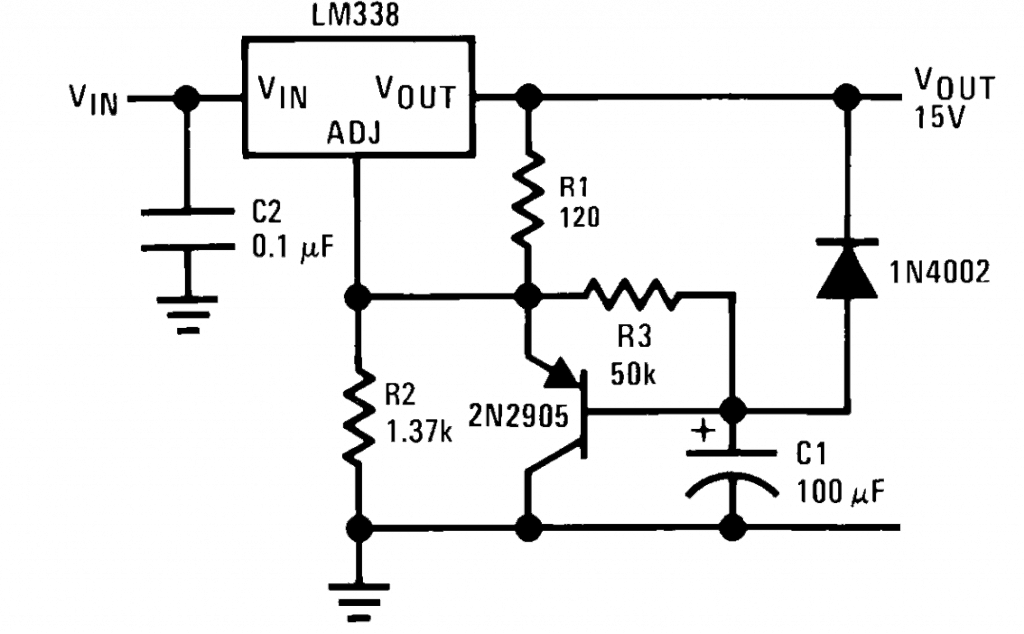
You can add the following delay based LM338 power supply to your existing power supply:
You can adjust R1/R2 to change the output voltage and adjust R3/C1 to change the delay to the desired levels.
Good evening, I’m working on a project that will require a 12V circuit board to control a 12V solenoid. It seems basic and assumed i would be able to find this board with out much trouble but so far ive proven myself wrong. I need the circuit board to switch on my solenoid for 3-5 seconds ( i dont know exactly yet) one time every 30 days. Obviously the 30 day delay is the hurdle I’m encountering Could you get me on track to building this board?
Hi, the 30 delay can be solved with a day/night light detector, which will detect the passing of each day with the help of the day/night light source. This day night pulse can be then converted into 30 day counting using 4017 IC, and subsequently at the final stage a 3 second delay timer can be added for activating the solenoid.
Thank you for the quick reply. The day/night detector would absolutely work but I left out a detail. My mistake. The device for this project will be 100% indoors and set up either in a closet or the attic. I won’t be able to wire in any kind of external day/night type device, I would need it to all be integrated in a standalone circuit board with a 12V power supply. Thank you again for your input
Oh, in that case in can be difficult for me to figure out an appropriate circuit design for you, because 30 day is a long delay and making a 30 day timer without errors can be quite difficult.
I need a simple solution for giving a little delayed impuls to a relay.
I already have the circuit which makes a short impulse out of the steady 12v connection.
1000uF in parallel to 10 Kohm on the negative input do the trick. Now I only need to happen this impulse (or the supply to this part of circuit) about one sec delayed. Time does not need to be exact.
I tried nearly all of your delay circuits but nothing worked;-(
My relay coil has 1kohm.
My favorite would be another rc circuit.
Can somebody please give me a hint how to combine those 2?
Thanks, VESPUCCI
All the above circuits are tested and are working. The above circuits are not for a single common application but have different applications. You cannot use all the above circuits for a single application, they won’t work. They all have different specific functions. You have to understand them and then apply.
To understand your application I will need the schematic of your diagram, without a schematic it may not be possible to find a solution.
Please try the following circuit:
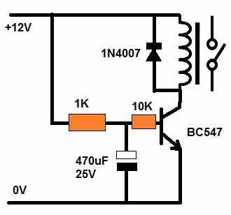
I tried with C945 transistor. But unfortunately not working;-(
No delay in powering. Very little delay after dividing.
It has to work, because it is a tested design, it is just about adjusting the resistors and their values.
Try the following modified circuit:
Hi. Your blog is very great. Please, can I explain my need? I was searching for a circuit that when in input receives a signal of 12V AC, whait for 30 seconds and after then send a 5VDC pulse to a relay. The delay and the activation time should be configurable. Thanks a lot.
Hi, thanks for liking the blog! You can try the following circuit. Your 12V will need to be converted to 12V Dc first. For providing 5V to the relay disconnect the emitter of the T2 BC557 and the connect this emitter with a 5V DC. Make sure to connect the ground of the 5V DC with the circuit ground:
T1 can be BC547 transistor.
R2 and C2 can be altered for adjusting the delay range
Hi my name is Pete I have just built a 300 led hex style sci – fi computer display when first turn on all the leds are red and whilst the timers in the devices are running at different rates for the first 2/3 minutes the effect is great after this time the slow change diodes don’t look too impressive . I need a circuit that will will switch on for 2/5 minutes then crash to 0 volts and recycle again at 5 volts for 2/5 minutes before repeating the same be nice if i could actually vary the time with a potentiometer to experiment and gauge the exact best time to gain maximum led colour difference and thus the best decorative effect. Regards Pete Mantle
Hello Pete, I did not understand what you meant by 2/5 minutes, please clarify!
i meant a variable control time from say 2 minutes to 5 or even 6 minutes i want to be able to vary the time with a pot to experiment for best results i really need the 5volts to collapse pretty fast also in order to reset the leds to red ( the starting colour ) thanks for your swift response
You can do it with a help of a simple IC 555 flasher, as shown below. The pin#3 will alternately oscillate from positive supply level to 0V level. The ON OFF timings can be adjusted by adjusting the 1M pot and the 22K resistor values. But how will you use the pin#3 to control your LEDs? You will require a BJT or a MOSFET connected at pin#3 to do this:
to clarify I need t to deliver 5volts which will crash to zero after 2 to 6 minutes then restart AGAIN at 5 volts ( with a pot so I can vary the time interval ) then repeat the whole cycle again constantly. also need the voltage to completely hit zero in order to start the colour change leds at red .
Hi Swagatam,
Atoto Head Unit A6G2A7PF (2G+32g)
I have installed the above head unit in my diesel Toyota Prado 120 Series.
The glow plugs in the engine take up to 5 seconds to heat after which I can start the car.
In this time my head unit begins to start but then crashes and restarts when I start the car, impacting recently adjusted settings e.g. steering wheel audio settings and who knows what else.
Is there a way to delay the start of the 12v (ignition on) to the unit so that it starts after the car is started?
I hope you can assist.
Wally
Hi Wally,
You can delay the 12V supply to the ignition circuit through the following circuit. The 12V supply to the ignition can be applied through the N/O relay contacts. The C2 R2 component values decide the delay time after which the relay will operate, once the input 12V to the circuit is switched ON.
Hi Swagatam, i have a question on the timers, i understand and have a grip on the single use sw from a transistor, however i need to stop an 74LS90 which is a single pulse/dragdown command then i need a second pulse/dragdown to reset the 74LS90. i am not sure it would work with a single pulse/dragdown from a single transistor to do both operations as they would be simultanious and atthe same time, do you have any ideas.
Hi Tim, I haven’t studied the 74LS90 IC yet so I am finding it difficult to figure out the problem.
Hi Sir,
My name is Fabio. I saw all your project but I need one with small modification if you can help please.
I need a Power ON Delay with 3 channel output controlling a MOSFET not a relay.
When power is applied the first channel wait 30s before come ON. The second channel will wait 60s after the first channel is ON, and the third channel wait 60s after the second channel is powered ON.
The time in “s” doesn’t need precise.
Hope you can help with this project.
Thanks
Hi Fabio,
I think the second concept from the following article will work for you. You will have to configure a MOSFET with the collectors of the BC557 transistors.
https://www.homemade-circuits.com/cube-light-circuits/
Is the PCB shown in the Delay ON Timer Circuit Working Details section available for sale?
Sorry, we don’t make PCBs now, so I may not be able to provide it to you, nevertheless you can easily get it done from any local PCB designer in your area. These PCB designs were not created by me rather purchased from an external source so please double check it before manufacturing.
Kindly I ask you what is 2m2 in the circuit best regards
2M2 = 2.2 meg ohm resistor.
Hi Swag
Many times your schematics have helped me but this time I cant cope myself. Imagine yarn winding mashine that has yarn tension motitoring via simpokle push button. Yarn stuck = machine stop. Problem is that any vibration of thicker yarn causes multiple false and unnecessary stops. My idea is that signal from button is transmitted only if it lasts more that say 0.5sec. Implementing microprocessor seems overkill to me.
One pole of switch is grounded and machine runs on 60v DC.
Do you thing any of your schematics will do ?
Hi Saul,
What type of switch are you using, is it a manual push button? in that case you may have to replace it with a relay operated switch to implement the switch debounce..
Yes simple micro switch is beeing used. It shorts some microcontroller input to ground to stop machine. I think transistor or mosfet will doo. Switch should trigger timer instead of what it did before. Does it have sense ?
OK, you can implement the following setup:
Take a BC547 transistor.
Connect the collector to the microcontroller input.
Connect the emitter to ground.
Connect the base to a 10k resistor.
Connect the other end of the 10k to one terminal of the microswitch, connect the other terminal of the microswitch to the positive line.
Connect a 1uF capacitor between base and ground.
It will work on 60 volt ?
Another question . Do I need resistor to discarge cap in order to not acumulate short burst chargindg ?
For 60v you can use BC639 bjt. To ensure proper discharge of the capacitor you can connect a 2.2k resistor parallel to the capacitor.
Thanks a lot.
Your advices are very helpfull.
Glad to help!
Very nice site for electronics guys. I was going through self contained power transformerless power supply circuit and was fascinated by its simplicity without using transformer at all. Moreover, triac in circuit seems to be more effective and efficient than relay. But how to modify this circuit for mains supply to automatically turn on after a pre-defined period (say of 5-15 seconds) without the use of push button?
Thank you Vikas, Glad you liked the site.
For a delay ON, mains operated circuit, you can refer to the first circuit from the following link:
https://www.homemade-circuits.com/simple-refrigerator-protector-circuit/
Hi Swag,
I forgot to add one additional query for self contained power transformerless power supply circuit. It seems to be good for single application. But can certain modifications be made in circuit to place it just after electric meter? This will help in bypassing sudden surge during power supply in case of power failure.
Hi Vikas,
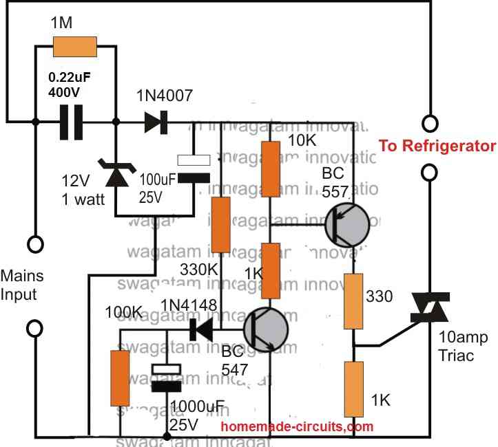
Yes, that’s possible if you are able to configure the wiring correctly.
You can configure the following circuit which will ensure safety from sudden power ON surge.
Hi Bill
I am a newcomer to your sight as you must realise and i find the content very handy and informative. However i have a situation that i hope you may be able to resolve. I need to be able to identify when a battery source of 12v dc (li iron sealed) drops its voltage to about 10.5 v and triggers a 3 second (approx.) timer to operate a small solenoid. The solenoid will still operate at this voltage. I would prefer to be able to do it without a relay. The trigger as well must only be able to operate once so as not to keep the solenoid on. The system will reset again after the battery is recharge. I am a retired electrician which makes me dangerous in this field so please understand my ignorance in these matters. I have always had a yen to get into this field as a hobby and now have the chance. Hope you can help. Regards Col R
Hi Colin,
I will try to figure out the circuit soon, and let you know.
If you have any further questions please feel free to ask…
Thanks Bill
Hi again,
Here’s the circuit you can try, it should hopefully fulfil your requirement:
Hi Bill Thanks for replying so quickly. Could you advise me of the value of RX and CX in the circuit you supplied. Regards Col R
RX can be around 33k and CX can be around 100uF, for getting an ON time pulse of 3 seconds.
Thank you
Hello,
So, I have an application where I am using a D-type flip-flop to toggle my load using a pushbutton. I want to add a trip functionality, so when a trip signal comes, after 5 seconds will the load be turned off. If the trip signal goes out before 5 seconds, the load stays on. If it goes out after 5 seconds, the load will turn on again.
Please explain the delay trigger operation with more details, I may try to solve it.
So the circuit that starts with the output being high when you power it on. Now, when you give it a high signal through the dry contact input, it waits for 5 seconds. If the input stays high for the whole 5 seconds, the output switches to low. But if the input goes low before the 5 seconds are up, the timer resets, and the output stays high. Once the output goes low after the 5-second delay, it stays low as long as the input is high. And when the input finally goes low, the output immediately goes back to being high.
Ok, you can try this circuit:
Hi Swagatam,
I have come across your blog and love it as I have been an enthusiast for long. I don’t design electronics.
I’m making a battery powered drone. I would like to have an on-off control which can be controlled with a tac push button. A 3 second contact to power on the electeonics and 3 seconds press to turn it off.
The current in drone circuit is very high, about 60 amps. Unable to find the solution as weight and space are critical on this small drone.
Should this be software controlled? Can you please help?
Thank you Gajendra, for your question!
The circuit can be perhaps designed using a 4017 IC and a 555 IC.
Just wanted to know, is the ON/OFF operations done with a single tact switch?
And, what happens if the switch is not released after 3 seconds, and remains pressed for more 3 seconds?
Kindly clarify the above, I will try to help!
hi.
I want to control an electric motor with a relay.
I want the relay to close 5 seconds later when the current to the relay coil is cut off.Can you help me with this?
Thank you for everything
Hi, you can try the 2nd circuit from the above article. Replace the LED/resistor with your relay, and make sure to add a freewheeling diode across the relay coil…Adjust the 2M2 and the 1000uF values to get the desired 5 second delay-off time.
Howdy Swagatam,
Great site and very much appreciated even though I have just discovered it. I have been looking for information on designing a very simple timing circuit on a 12vdc system. Timer will be on a grounded side inititially. when circuit is switched on there need s to be a momentary delay of 1-2 seconds before going high, and then again a momentary delay before going back to ground. It shall remain this way until circuit is powered down then it will reset.
Thank you for your time!
JC
Thank you Jeff, glad you found the site helpful!
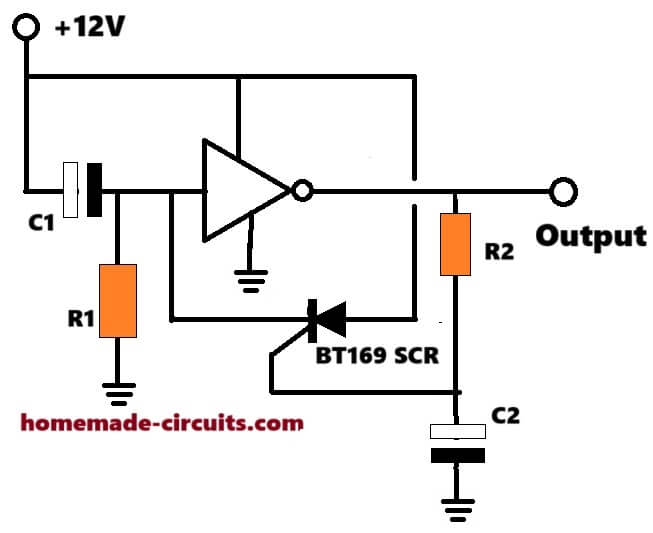
I think the following circuit should be able to fulfil your requirement:
Pease let know how it works.
You will have to adjust the relevant RC components appropriately for getting the desired timing outputs.
Hello sir. I have been following you for a long time, and I have realized many of your projects. At one of the circuits presented by you, can it be done that timing is repeated after a certain period of time automatically? You mean, like, cyclical?Work for 1 minute and stay for 3 minutes?Respectfully.
Thank you so much Gelu,
You can try the first circuit from the following article for getting a separately adjustable ON/OFF timing for the load:
https://www.homemade-circuits.com/how-to-use-ic-555-for-generating-pwm/
Make sure to increase the values of the 47uF capacitor and the 5k pot as per your maximum on or off time specifications
Thanks sir, your explanations are more comprehensible for newbies like me. However, I have a slightly different challenge for my work. I actually need a workaround in which a dc motor can ONLY be activated in;
– an open circuit after the button is depressed AND RELEASED (it doesn’t how long), or,
– in a CLOSED circuit, after the button is open (again, the intervals won’t matter) and closed again. The supply volts is 12vdc.
Thanks. I hope you do understand what I was trying to explain
Thanks Richard,
Sorry, I did not understand the operations correctly. What is “Open” and “closed” circuit?
Please let’s continue the discussion under a “motor” related article:
https://www.homemade-circuits.com/dc-motor-speed-controller-circuits/
Hello.
Thank You for the article. I have very basic electronic knowledge but with the article I was able to make circuit I need.
My case: I have a photographic lamp as a part of my workbench setup. The lamp is electronically controlled with pushbuttons. It have one annoyance, does not remember on/off state when power is cut. Every time I turn on main power switch for whole workbench, I have to grab the lamp and hold a button. First I tried to lock the button pressed, but after few minutes the lamp goes off.
The lamp PCB is made with very small SMD components, but I should be able to hook wires to the button, ground and 5V. Microcontroller is operating on 3.3V and on/off pin is connected to pullup 10k resistor. My delay circuit bypass the button and sets the pin low for a few seconds after power rail goes high. I added transistor for faster circuit reset / capacitor discharge.
I have question about above circuits, I can’t grasp what exactly diodes connected to transistor base and emitter are doing. This two: imgur.com/a/u6PuAE2
The emitter one is making base voltage higher and pulse longer, my guess would be that it should clamp voltage and make transition edge sharp, instead it looks like the diode is changing transistors operating point.
And the base diode doesn’t make much difference, it is only making capacitor discharge longer because current can’t run through transistor, changing it to small current limiting resistor makes the circuit ready for new pulse faster.
Here is my circuit:
imgur.com/a/HRiK1bo
Hi, I guess you are referring to the following circuit. Your assumption regarding the emitter diode is correct.
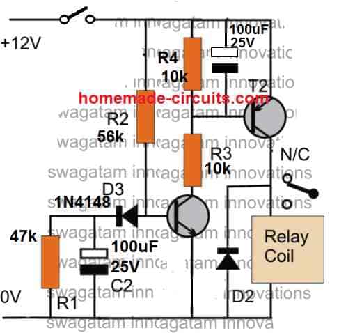
However, the base diode is also very important, which ensures that the circuit works only as a “delay ON” timer and not as a “delay OFF” timer. If you remove the base diode, then the circuit will start functioning as both delay ON and delay OFF timer which we don’t want. You image link is not opening in my browser at the current moment.
The base diode have a sens now. Thanks. I haven’t thought about delay off, because in my circuit “off” means power down. I wanted to discharge capacitor quickly to make next pulse ready in case of some interrupted power switching or rare power line flicker.
The image link works if copied and pasted into browser. I don’t see rules for the website comments about pasting links, BB code or html tags, I’ll try paste it again in different form and hopefully the comment wont by automatically removed :).
[url]https://imgur.com/a/HRiK1bo[/url]
Unfortunately, there’s no easier way to discharge the capacitor, except using the parallel resistor, which cannot be small.
There’s no rule for posting the links, I can handle and process the links while moderating the comments.
The link still doesn’t open, it gives me the following error:
{“data”:{“error”:”Imgur is temporarily over capacity. Please try again later.”},”success”:false,”status”:403}
The circuit image uploaded to different hosting:
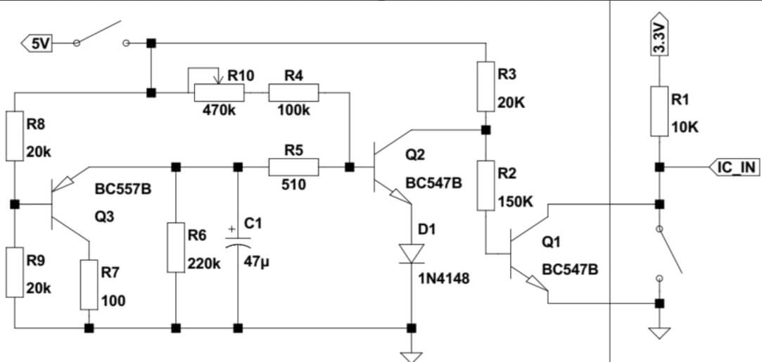
To make the BC557 discharge the capacitor at power switch OFF, the R8 must be replaced with the short circuit. Still, the discharging will not be efficient because the moment the charge across the capacitor drops below 0.6V, Q3 will shut down. Also, the R5 must be replaced with the diode.
I can’t figure out the function of Q1, it will simply invert the Q2 “delay ON” feature…
Hello.
I used Your circuit with two transistors as a base for tinkering, that why there are two transistors in my circuit. Here is much simpler, one transistor circuit, which gives enough pulse length for my need. I added diode witch is discharging capacitor in simulation, but I’m not sure if it will work in reality or is it a simulation quirk.
Thanks for sharing your design,
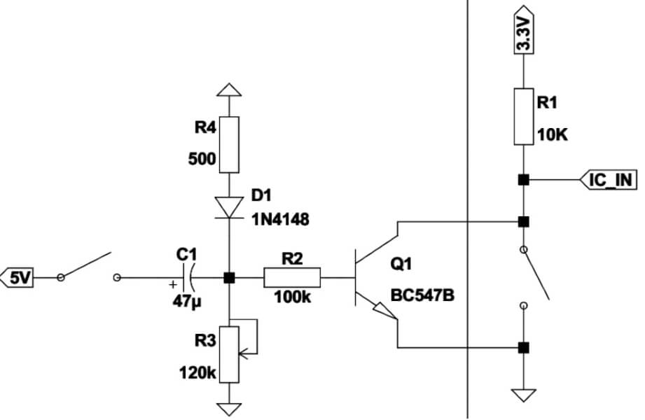
Single BJT circuit will provide less delay time and require larger part values compared to a two BJT circuit. If a single BJT works for you then it is fine.
The capacitor in your circuit has no chance to discharge once the trigger switch is turned off, you must connect another resistor between the (+) of the capacitor and ground….the diode D1 and R4 has absolutely no role to play in the circuit and must be removed.
sir mujhe ek 24 volt se chalane wala delay circuit ki jarurat hai jo 5 se 20 secand tak voltage delay kar sake
bina trigar switch ke
Ashish, you can try the following circuit, just make sure to change the relay coil voltage to 24V
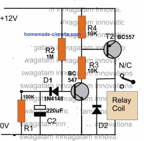
I am looking for a simple circuit to control a start winding of a compressor motor. The start coil and capacitor are connected in series. And use a common 120v which is shared with the run winding and capacitor in series.
Can you please provide a basic simple circuit which uses a transistor or mosfet to turn off the start winding after a few seconds? Please try and make the circuit as simple as possible only using resistors, diodes, capacitors, and an npn mosfet/transistor.
Since a compressor motor is an AC system, MOSFETs or BJTs might not work, so you might have to use a triac instead. You can try the following design and see if it works or not:
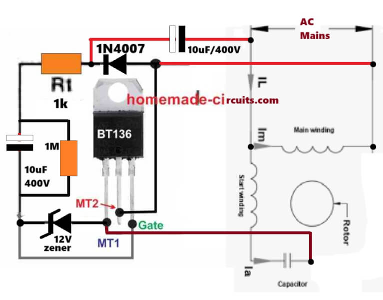
Hi Swagatam,
I’ve been looking for a similar solution: a fast spin-up circuit for a “dimmed” universal motor. AKA overshoot at switch-on. It’s a pump and when the pressure drops below a set threshold the motor needs to recover it first (also spinning up and starting to move the water in the pipes as well) then to fall back to the operating power/RPM. It takes about 2..3 secs.
I’ve recognized some parts of this circuit at one of your previous posts: https://www.homemade-circuits.com/simple-triac-triggering-circuits-explained/#:~:text=Figure%202
I haven’t found anything similar to this circuit. Also, I don’t seem to get how a 10uF capacitor could produce efficient delay. Neither I see the purpose of the capacitor at the very top of this schematics.
May I also note that my mains is 240VAC and I already have a BTA06 (I_G=5..50mA, instead of 10..25mA of a BT136) dimmer PCB present, connected to the pump motor.
Any help much appreciated.
Thanks in advance, KGy
Thanks KGy,
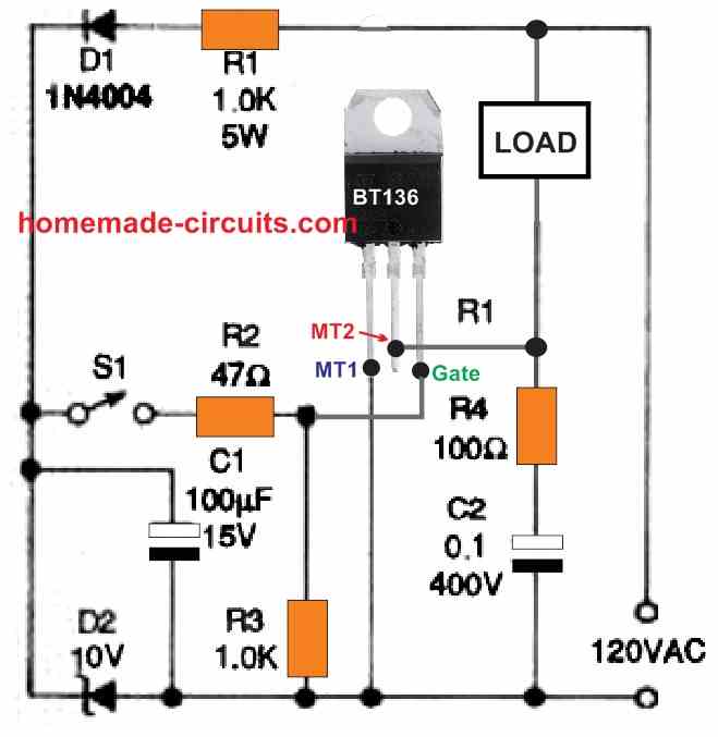
Are you referring to the following circuit? In this circuit, the delay capacitor is rated at 100uF, and there’s no capacitor at the top…please let me know which diagram you are actually referring to:
Hi Swagatam,
Thank you very much for coming back to me. You are a star.
Yes, that’s the one. The timing cap is electrolytic, not poly. Furthermore, -if I’m right- it delays the switch-on.
What I need is additional circuit to the basic triac dimmer that opens the gate for a full-cycle for a couple of seconds.
Where I see the problem lies is that a delay and a trigger circuits need to work alongside.
My best guess would be to utilize a diode-bridge for this.
There are plenty schematics for soft-starters but I need the opposite, which I believe is more complicated.
I hope with it I managed to clarified my needs / circumstances.
Thank you so much,
KGy
P.S. I believe this line of my comment is ambiguous/needs clarification: > I haven’t found anything similar to this circuit.
I meant the one you’ve posted here/I’m replying to. I didn’t manage to find anything similar on the Internet. Neither using the image nor the keywords “start.winding” “compressor”, etc.
Thank you KGy,
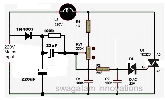
Though not 100% sure, I think the following configuration can be used to keep the load dimmed normally, and boost the power only during power switch ON, for a couple of seconds, you can try this and let us know how it goes:
Dear Sir,
on “Delay ON Timer Circuit Working Details”, C2 is not discharged quickly, so if mains power fails and returns before C2 is discharged, then delay-on time will be shortened.
Any suggestion for the above problem ?
TNX
Yorgos
GREECE
Hi Yorgos, please try the following modification, and let me know if it works or not:
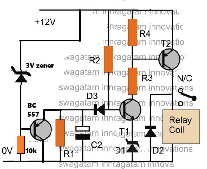
YOUR WORKS ARE AWESOME BROTHER , AND HELPING OTHERS , ITS WORTH A VISIT
Thanks bro, I appreciate your kind words and glad you liked this site…
Hi there,
I have been tasked with creating something to allow a button to be pressed, there be a 5 second delay(ideally with a visual countdown) and then power up a light to give one single flash and then reset to be used again. All the products/circuits i seem to find all want to delay and then switch on, not flash. Is such a thing possible ? Or am i fighting a losing battle ?
Even just a yes it’s possible would inspire me to keep reaseaching although its been 20+ years since i’ve worked with circuit boards.
hope you can help.
thanks
Richard
Hi, do you need this circuit using only transistors or an IC will also do? Because an IC can work more efficiently…
Hi there, thank you for responding.
I’m looking for the most reliable and efficient way to do this, so i guess an IC would be better however i would go with whichever way you think is best.
thanks
Richard
Ok, I have designed it with transistors, you can check it out below. The right/bottom transistor is BC547, Rx and Cx must be adjusted to get the required 5 second ON time delay.
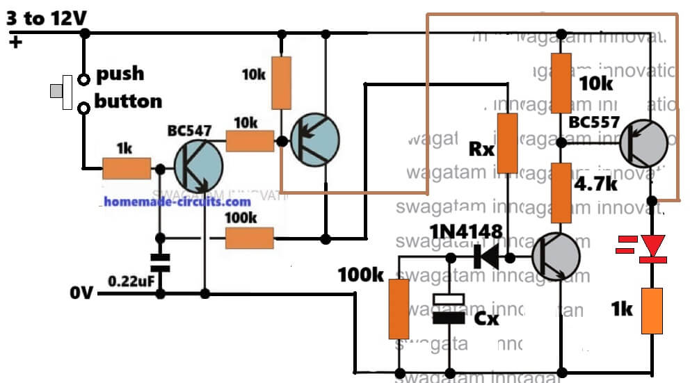
Wow, thank you for that. I will start assmbly and let you know how it goes.
Thanks again
Richard
Sure, no problem, all the best to you…please make and test the stages step-wise.
Hi, there’s one mistake in the previous circuit diagram which i gave you.
Please make sure to add a diode in series with the brown colored wire which connects the collector of the right side BC557 with the base of left side BC557. Cathode towards left side BC557 and anode towards right side BC557…
And also please reduce the positive to base 10k resistor value of the left side BC557 to 4.7k.
hi Mr. Swagatam.
I’m Indra, I have a 3d printer machine. I want to make a timer circuit off with an adjustable time. I am interested in your timer circuit using the Triac BT 36 so it doesn’t use relays or DC voltage. how does the circuit work so that after the button is pressed, the AC voltage on the load will be off at a selectable time.
Hi Indra,
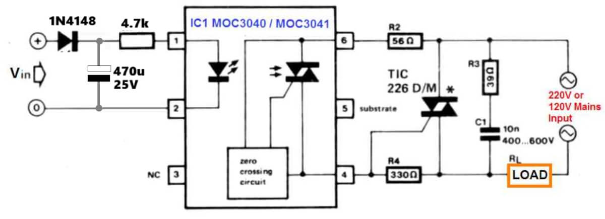
For a short delay you can do it quickly and safely by employing the following concept:
If you need relatively longer delays then the LED side might require a BJT based timer stage…
thanks for your reply..what in left side?vin? mean dc voltage?
Yes, your DC input through the push button…
Thanks for your reply..maybe i will try your circuit with triac bt 36,no DC, no relay, coz i want simplest circuit for off timer. if you have another suggestion for my need..just mail me :)..thanks for your help
Ok great, you can definitely use my design using BT136 triac, as given below, let me know if you have any issues with the circuit…:

Hello Mr. ____
I’m interested in the great offer on your website. I’m trying to build a timer that turns on a machine at specific intervals and keeps it running for a specific number of minutes, based on settings I’ve configured in advance. I have selected two integrated circuits, the CD4060, one configured as an astable multivibrator and the other as a monostable multivibrator. The machine’s activation times have 5 options (2, 2.5, 3, 4, or 5 hours), and the duration it will remain active until it shuts off has 5 options (10, 15, 20, 30, or 40 minutes). Instead of a Relief, I would like a MOSFET. The machine has a power consumption of ~10W (24V/~0.5A). Is there a schematic available?
Yannis (John) from Greece.
Translated with DeepL.com (free version)
Hi, I guess you have already configured the 4060 circuit, in that case do you want only the MOSFET stage?
I haven’t used MOSFETs before, and I’m not sure whether I should use an N-channel or a P-channel MOSFET, or what the correct connection is. I’m using Pin 3 (Q14) on both CD4060s; is this believed to be correct for the timing I’m aiming for, so I don’t have to use very large resistors and capacitors? I calculated the timing (though I’m not entirely sure) and want to use 5 different resistors (1M, 1.2M, 1.5M, 1.8M, 2.4M) for the astable circuit and 5 (100K, 180K, 250K, 420K, 600K) for the monostable circuit, selected via two rotary switches (1×5), and keep the capacitor fixed at a low value (470 nF) for greater accuracy. If you are familiar with this and have time, I would appreciate your help.
Translated with DeepL.com (free version)
Yes Pin 3 (Q14) of the CD4060 looks correct here if long timing delays are needed, because then RC values can stay reasonably smaller instead of using extremely huge resistors or capacitors everywhere.
That idea of using rotary switches with different resistor values and one fixed 470nF capacitor also looks good actually.
For electronic switching of those timing resistors, an N-channel MOSFET is generally easier to use if switching is done on the ground side…
And yep, those resistor ranges you selected seem reasonable for experimenting with the CD4060 oscillator section..
Yes, I’ve set it up, but I wanted to confirm with you. Thank you for the helpful information. If you could draw a simple diagram showing how to replace the relay with an N-channel MOSFET, that would be a great help.
Sure, you can follow the below given ideal MOSFET connection setup: