In this post I have explained the making of simple delay timers using very ordinary components like transistors, capacitors and diodes. All these circuits will produce delay ON or delay OFF time intervals at the output for a predetermined period, from a few seconds to many minutes. All the designs are fully adjustable.
Importance of Delay Timers
In many electronic circuit applications a delay of a few seconds or minutes becomes a crucial requirement for ensuring correct operation of the circuit. Without the specified delay the circuit could malfunction or even get damaged.
Let's analyze the various configurations in details.
You may also want to read about IC 555 based delay timers. Recommended for you!
Using a Single Transistor and Push Button
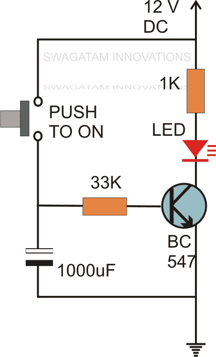
The first circuit diagram shows how a transistors and a few other passive components may be connected for acquiring the intended delay timing outputs.
The transistor has been provided with the usual base resistor for the current limiting functions.
A LED which is used here just indication purposes behaves like the collector load of the circuit.
A capacitor, which is the crucial part of the circuit gets the specific position in the circuit, we can see that it's been placed at the other end of the base resistor and not directly to the base of the transistor.
A push button is used to initiate the circuit.
On depressing the button momentarily, a positive voltage from the supply line enters the base resistor and switches ON the transistor and subsequently the LED.
However in the course of the above action, the capacitor also gets charged fully.
On releasing the push button, though the power to the base gets disconnected, the transistor continues to conduct with the aid of the stored energy in the capacitor which now starts discharging its stored charge via the transistor.
The LED also stays switched ON until the capacitor gets fully discharged.
Te value of the capacitor determines the time delay or for how long the transistor stays in the conducting mode.
Along with the capacitor, the value of the base resistor also plays an important role in determining the timing for which the transistor remains switched ON after the push button is released.
However the circuit using just one transistor will be able to produce time delays which may range only for a few seconds.
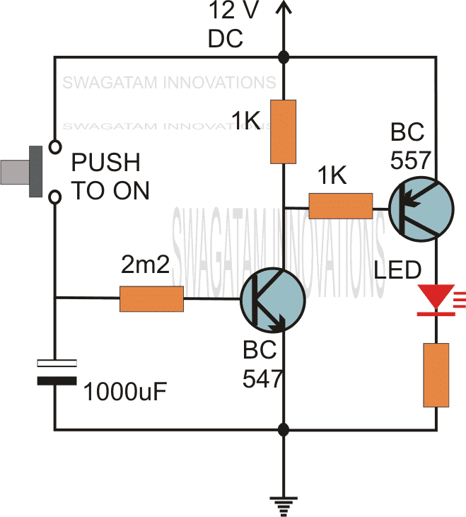
By adding one more transistor stage (next figure) the above time delay range can be increased significantly.
The addition of another transistor stage increases the sensitivity of the circuit, which enables the use of larger values of the timing resistor thereby enhancing the time delay range of the circuit.
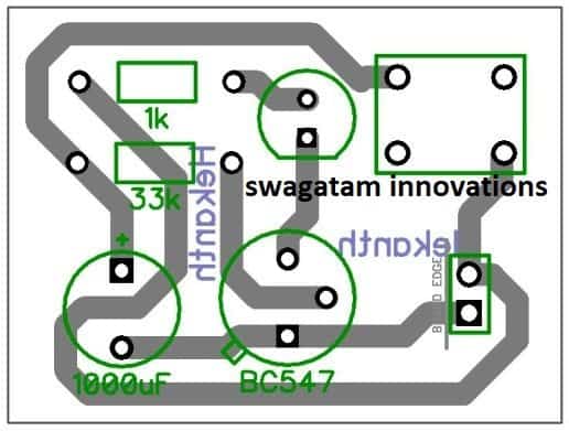
PCB Design
Video Demonstration
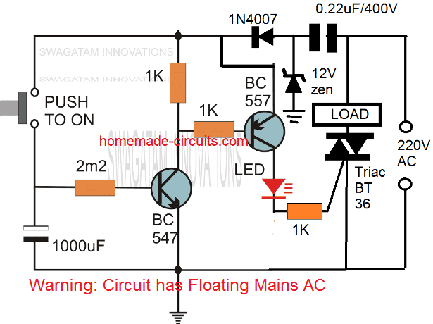
Using a Triac:
The following image shows how the above delay timer circuit may be integrated with a triac and used for toggling a mains AC operated load
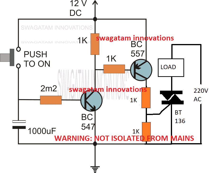
The above could be further modified with a self contained power transformerless power supply as shown below:
Without a Push-Button
If the above design is intended to be used without a push button, the same may be implemented as indicated in the following diagram:
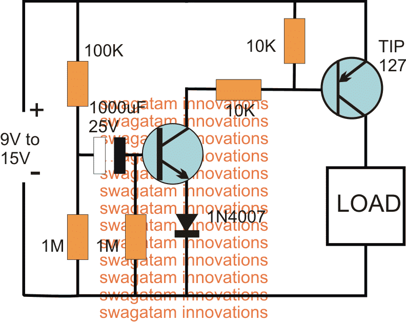
The above delay OFF effect without a push button can be further improved by using two NPN transistor, and by using the capacitor across base/ground of the left NPN
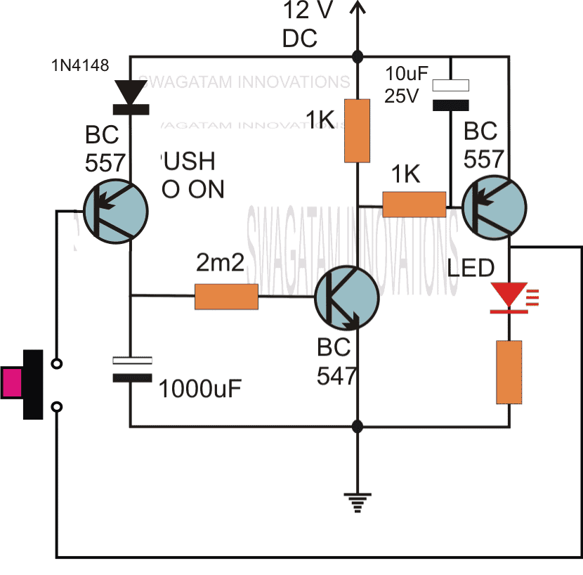
The following circuit shows how the associated push button may be rendered inactive as soon as it's pressed and while the delay timer is in the activated state.
During this time any further pressing of the push button has no impact on the timer as long as the output is active or until the timer has finished its delay operation.
Delay from an External Trigger
Problem asked by Mr. Glen (one of the dedicated readers of this blog):
I have a situation where I have a pulse of 12V that lasts about 4 seconds (from a rotary switch being turned by a slow motor) but I only want about half a second pulse (to trigger a mechanical bell/chime).
Is there any way to take a long pulse into a circuit and send a much shorter pulse out?
The solution to the above problem is provided in the following schematic:
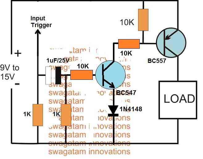
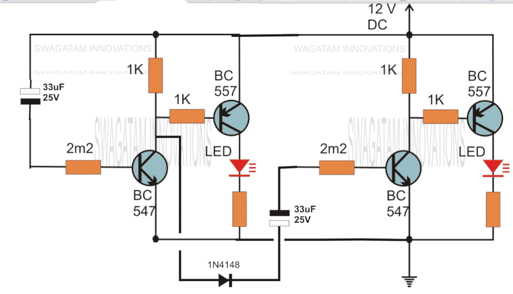
Two Step Sequential Timer
The above circuit can be modified to produce a two step sequential delay generator. This circuit was requested by one of the avid readers of this blog, Mr.Marco.
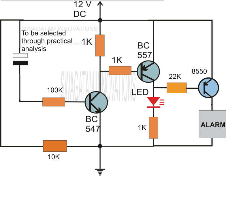
A simple delay OFF alarm circuit is shown in the following diagram.
The circuit was requested by Dmats.
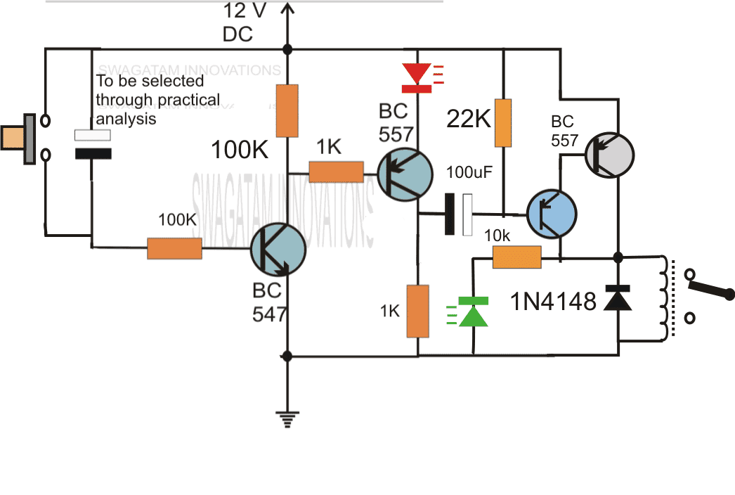
The following circuit was requested by Fastshack3
Delay Timer with Relay
"I am looking to build a circuit that would control an output relay. This would be done in 12V and the sequence will be initiated by a manual switch.
I will need an adjustable time delay (possibly displayed time) after the switch is released, then the output would go on for an adjustable time (also possibly displayed) before shutting off.
The sequence would not restart until the button was pressed and released again.
The time after the button release would be from 250 milliseconds to 5 seconds. The "on" time for the output to turn on the relay would be from 500 milliseconds to 30 seconds. Let me know if you can offer any insight. Thanks!"
So far we have learned how to make simple delay OFF timers now let us see how we can build a simple delay ON timer circuit which allows the connected load at the output to be switched ON with some predetermined delay after power switch ON.
The explained circuit can be used for all applications which calls for an initial delay ON feature for the connected load after the mains power is switched ON.
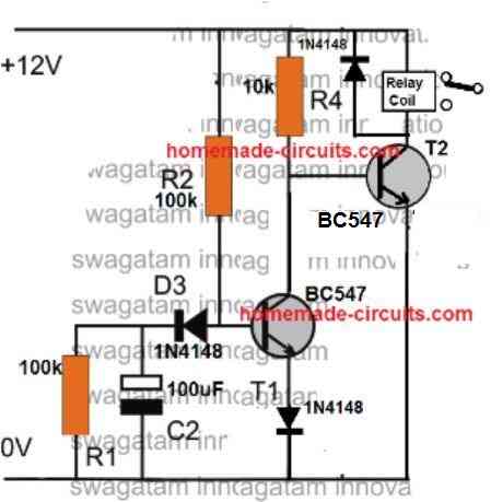
Delay ON Timer Circuit Working Details
The shown diagram is pretty straightforward yet provides the necessary actions very impressively, moreover the delay period is variable making the set up extremely useful for the proposed applications.
The functioning can be understood with the following points:
Assuming the load which requires the delay ON action being connected across the relay contacts, when power is switched ON, the 12V DC passes via R2 but is unable to reach the base of T1 because initially, C2 acts as a short across ground.
The voltage thus passes through R2, gets dropped to relevant limits and starts charging C2.
Once C2 charges up to a level which develops a potential of 0.3 to 0.6V (+ zener voltage) at the base of T1, T1 is instantly switched ON, toggling T2, and the relay subsequently....finally the load gets switched ON too.
The above process induces the required delay for switching ON the load.
The delay period may be set by appropriately selecting the values of R2 and C2.
R1 ensures that C2 quickly discharges through it so that the circuit attains the stand by position as soon as possible.
D3 blocks the charge from reaching the base of T1.
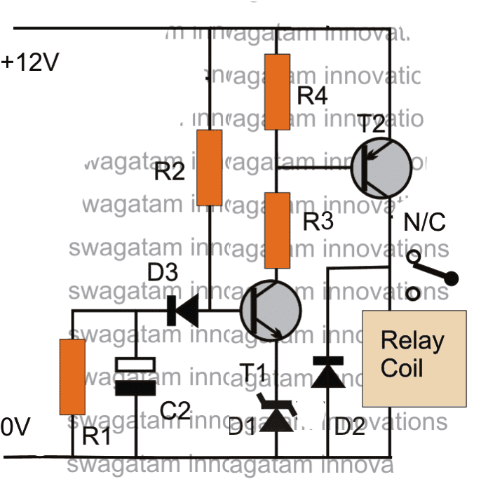
Parts List
R1 = 100K (Resistor for Discharging C2 when circuit is switched OFF))
R2 = 330K (Timing Resistor)
R3= 10K
R4 = 10K
D1 = 3V zener diode (Optional, could be replaced with a wire link)
D2 = 1N4007
D3 = 1N4148
T1 = BC547
T2 = BC557
C2 = 33uF/25V (Timing Capacitor)
Relay = SPDT, 12V/400 Ohms
PCB Design
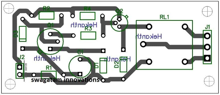
Application Note
I have explained how the above delay ON timer circuit becomes applicable for solving the following presented issue by one of the keen followers of this blog, Mr. Nishant.
Circuit Problem:
Hello Sir,
I have a 1KVA automatic voltage stabilizer.It has one defect that when it is switched on, very high voltage is outputted for about 1.5s (therefore cfls and bulb got fused frequently) after that the voltage becomes OK.
I have opened the stabilizer it consist of an auto-transformer,4 24V relay each relay connected to a separate circuit(each consisting of
10K preset,BC547,zener diode,BDX53BFP npn darlington pair transistor IC,220uF/63v capacitor,100uF/40V capacitor ,4 diodes and some resistors).
These circuits are powered by a step down transformer and output of these circuit are taken across corresponding 100uF/40V capacitor and fed to corresponding relay.What to do in order to tackle the problem.please help me.Hand drawn circuit diagram is attached.
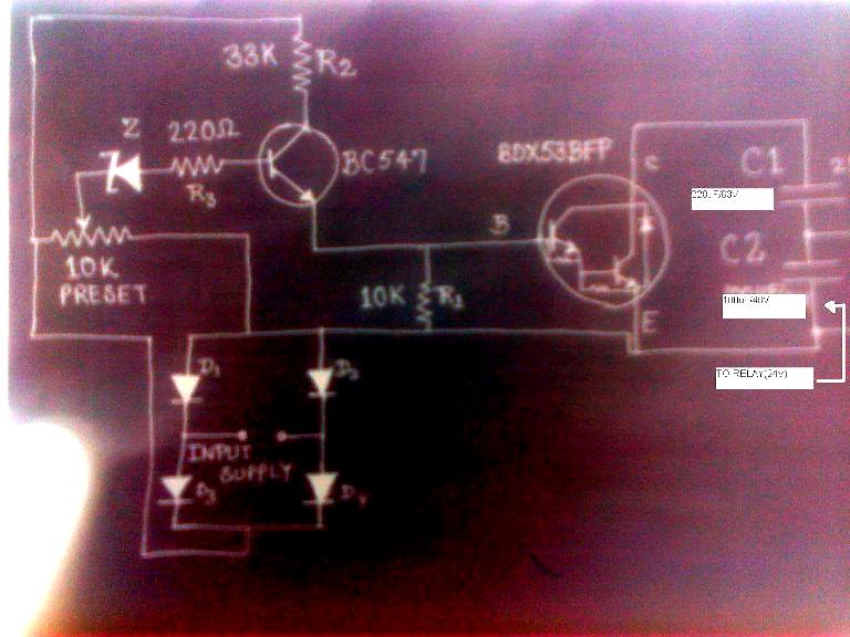
Solving the Circuit Problem
The problem in the above circuit might be due to two reasons: one of the relays is switching ON momentarily connecting the wrong contacts with the output, or one of the responsible relays is settling down with the correct voltages a little while after power switch ON.
Since there are more than one relay, tracing out the fault and correcting it can be a bit tedious......the circuit of a delay ON timer explained in the above article could be actually very effective for the discussed purpose.
The connections are rather simple.
Using a 7812 IC, the delay timer can be powered from the existing 24V supply of the stabilizer.
Next, the delay relay N/O contacts may be wired in series with the stabilizer output socket wiring.
The above wiring would instantly take care of the issues as now the output would switch after some time during power witch ONs, allowing enough time for the internal relays to settle down with the correct voltages across their output contacts.
Feedback from Mr. Bill
Hi Swagatam,
I stumbled across your page doing research on the web to make my delay more consistent.Some back ground information first.
I am a bracket drag racer and launch the car on first sight of the 3rd amber bulb as the christmas tree is coming down.
I use a transbrake switch that is depressed to lock the automatic transmission in forward and reverse at the same time.
This allows you to rev up the engine to build power for launch. When the button is released the transmission comes out of reverse and moves the car forward under high rpm.
This is like popping the clutch on a manual transmission car, anyway my car reacts to quickly and the result is a redlight, leaving to early, and you lose the race.
In dragracing your reaction time on the launch is everything and it is a game of hundreths-thousanths with the big boys, so I have put the transbrake switch on a relay and put a 1100uf cap combo across the relay to delay its release.
Because of the car electronics I don't believe there is a precise voltage charging this cap every time I activate this circuit and precision is key so I bought a power stabilizer off of Ebay that takes 8-15 volts in and gives a consistent 12volts out.
This turned my season around but i believe this circuit could be made to be more precise and to vary the delay time in an easier way rather than swap cap combos.
Also should I run a diode in front of the relay, not currently because all that is there is the on off switch- where will the current go? I am not an electrical engineer by any means but do have some knowledge from trouble shooting high end audio for many years.
Would love your thoughts- thankyou
Bill Korecky
Analyzing and Solving the Circuit
Hi Bill,
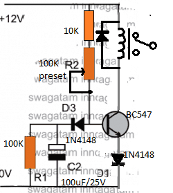
I have attached the schematic of an adjustable delay circuit, please check it out. You can use it for the mentioned purpose.
The 100K preset can used and adjusted for acquiring precise short delay periods as per your specifications.
However, please note that, the supply voltage will need to be minimum 11V, for the 12V relay to operate correctly, if this is not fulfilled then the circuit might malfunction.
Regards.
Simple 5 to 20 Minute Delay Timer
The following section discusses a simple 5 to 20 minute delay timer circuit for a specific industrial application.
The idea was requested by Mr. Jonathan.
Technical Requirements
While trying to figure out a solution to my problem on google, I came across your above posting.
I'm trying to figure out how to build a better Sous Vide controller. The main problem is that my water bath has a very high hysteresis, and when heating from colder temperatures will overshoot about 7 degrees from the temperature at which power is terminated.
It is also very well insulated, with a gap between the inner and outer vessel which makes it act like a thermos jar, because of this it takes a very long time to decline from any excess temperature. My PID controller has an SSR control output and a relay alarm output.
The alarm can be programmed as a below limit alarm with an offset from the set-point. I can use a five volt supply I already have for my circulation motor to run through the alarm relay and drive the same SSR the control output is driving.
To be on the safe side and protect the PID controller I'll add a diode to both the alarm voltage and the control voltage to prevent one output from feeding back into the other.
I'll then set the alarm to stay on until the temperature rises above the set-point minus 7 degrees. This will allow the PID tuning to be adjusted without having to account for the initial temperature ramp-up.
Because I know that last few degrees will be achieved without any power input, I'd really like a way to delay any recognition of the control signal for about five minutes after the alarm shuts off, as it will still be calling for heat.
This is the part I've yet to figure out the circuitry for. I’m thinking of a normally closed relay in series with the control output, which is held open by the alarm signal.
When the alarm signal is terminated, I need a delay on the order of five minutes before the relay returns to its ‘off’ normally closed state.
I would appreciate help with the delayed off portion of the relay circuit. I like the simplicity of the initial designs on the page, but I get the impression they wouldn’t handle anywhere near five minutes.
Thank you,
Jonathan Lundquist
The Circuit Design
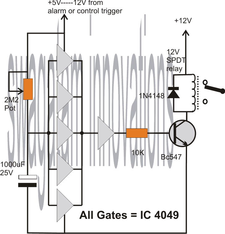
The following circuit design of a simple 5 to 20 minute delay timer circuit can be suitably applied for the above specified application.
The circuit employs the IC4049 for the required NOT gates which are configured as voltage comparators.
The 5 gates in parallel form the sensing section and provides the required time delay trigger to the subsequent buffer and the relay driver stages.
The control input is acquired from the alarm output as indicated in the above description. This input becomes the switching voltage for the proposed timer circuit.
On receiving this trigger, the input of the 5 NOT gates are initially held at logic zero because the capacitor grounds the initial trigger via the 2m2 pot.
Depending upon the 2m2 setting, the capacitor starts charging up and the moment the voltage across the capacitor reaches a recognizable value, the NOT gates revert their output to logic low, which is translated as a logic high at the output of the right single NOT gate.
This instantly triggers the connected transistor and the relay for the required delay output across the relay contacts.
The 2M2 pot may be adjusted for determining the required delays.
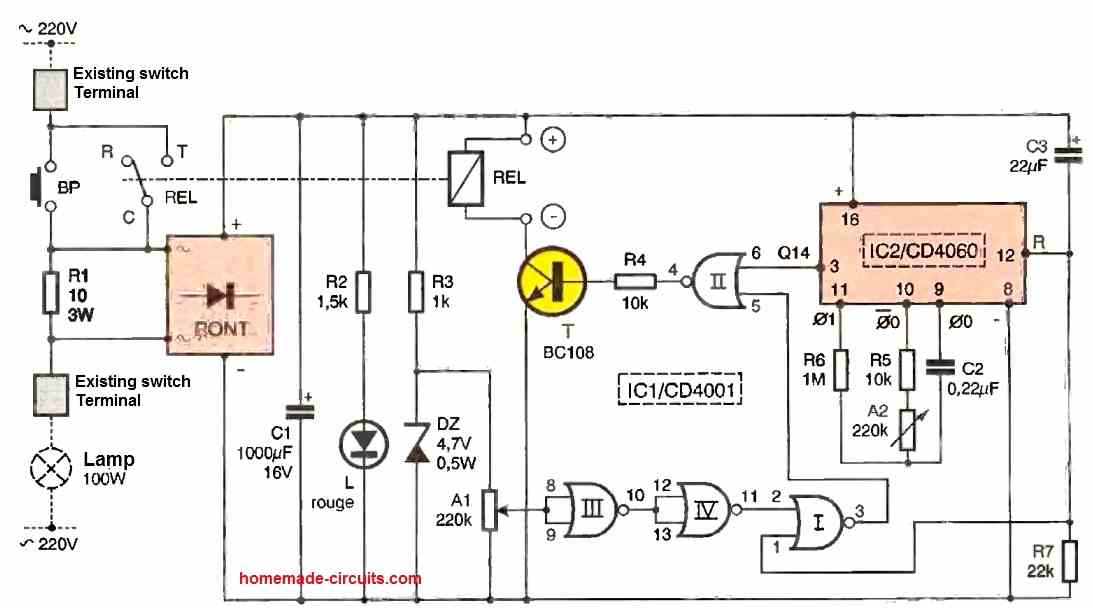
Circuit Diagram



Questions & Answers
I guess your need matches the one explained in the following article:
https://www.homemade-circuits.com/2013/06/programmable-bidirectional-motor-timer.html
Though it's quite complicated, probably it's the only way of doing it through discrete components.
The sequential timer can be surely designed, in fact I have already posted one such design in this blog, however I could not understand the connection between the motor rotation and the timing, if you could clarify that part then I could possibly suggest you an appropriate design.
Replace the push-switch in the second circuit with the tilt switch terminals with a series 1uF/25V capacitor.
I can provide a 4060 IC circuit, not a transistorized one.
Good day,
I have a 24vdc door activation circuit that I need a 5 second timer for. When the push paddles is depressed, I need to activate the latch relay for 3-5 seconds (to hold the latch open long enough for the operator to activate). Can one of your 12v circuits be modified to work with the 24vdc power supply?
Good day!
you can try the second circuit presented in the above article, replace the LED/resistor with the latch relay with protection diode.
The push button may be replaced with the paddle switch.
…the 1000uF cap should be tried with different values ranging from 10uF to 100uF for acquiring the required delay.
The 12V light should illuminate and timing initiated when the tilt switch is tilted the first time or after its tilted back to its original position??? please clarify this point.
I want to create a small, variable delay. Changing the resister on the transistor base will allow the delay to be adjusted?
Using a 12v supply, can you recommend what resistance and capacitance values I should experiment with to induce a delay between 0.1 and 0.5 seconds?
you can try the second circuit given in the above article, use a 1M pot in series with a 1K resistor at the base of the transistor and a 10uF capacitor
Hey everyone,
I am looking for a time delay circuit that I can use for some drop photography. I am looking to conenct a light gate to it so that when a drop breaks the gate it starts the time delay circuit then triggers my flash gun. (flash gun has a 2 wire cable to connect to circuit). Does anyone know of a circuit which can help me? If you could include the light gate into the circuit would be a bonus.
Thanks 🙂
Swagatam… i need circuit, that after power on the circuit , output should be 5 or 10 sec, delay…Please help.
you can try this:
https://www.homemade-circuits.com/2013/02/make-this-simple-delay-on-circuit.html
Good morning sir,
I am totally confused with so many timer/delay ckts. Please refer me a ckt.
as per my requirements.
1) I want to start a 12v/500mA (max)
d.c gear motor after 40-60sec of switching on and will run untill it is switched off.
2) Another previously related problem.please refer any 12-0-12 a.c to 12v d.c rectifier ckt.with component
list and diagram……thanks…..
With regards,
K. Kausik
Good morning kaushik,
you can try the following circuit, the values of C2, R2, D1 will decide the length of the ON time delay.
https://www.homemade-circuits.com/2013/02/make-this-simple-delay-on-circuit.html
please repeat your previous request, I am not able to remember it.
hi can you suggest to me a simple circuit with 15 components for me as an electronics student …………pls i know u can help me…
hi, you can try the following design:
https://www.homemade-circuits.com/2012/04/semi-automatic-water-level.html
i want to make ten LED light using time delay feature having fed one by one after specific time day.
Hi Swagatam,
I wanted to make a timer circuit which cuts off the supply to a circuit after 5-6 seconds after being triggered , even when the trigger is still on
Hi Shyam,
you can try the following design:
3.bp.blogspot.com/-FHAn8wSZwQ0/UrFIJJpYjgI/AAAAAAAAF7I/M8L5IqLxCwA/s1600/automatic+choke+solenoid+circuit.png
ignore the relay contact capacitors and wiring set up, it was drawn for a different application.
Thank you very much….
Hi Swagatam,
I Tried the circuit which you gave , but the relay never turns off… I have changed the capacitor values ,but also no change…. can you please tell me what could be the problem.
Hi Shyam, I think I misread your requirement, the given circuit is good but is not applicable as per your need.
I'll give you a suitable one but let me know whether it should be a relay operated or without a relay, meaning the current requirement of the circuit is relatively higher or nominal??
Hi Swagatam, I wish to operate a 12v relay with this circuit. the current requirement is nominal.
Hi Shyam, I think the previous 555 based circuit which I recommended is perfect for your application and it'll surely work. Connect the relay between pin3 and ground, and make sure the line connecting pin4/8 of the IC gets the (+) 12V supply….remove the entire relay connections that's shown in the original diagram….your relay must be between pin3 and ground….let the 1N4007 diode be there with the coil, its anode will go to ground and cathode to pin3.
I thought that you wanted the entire circuit to get cut off after 5/6 sec but later realized that you wanted to execute the cut for another circuit via this timer circuit, therefore the suggested 555 circuit is right for the application.
Dear Sir ,it still doesn't work because, as I had mentioned earlier the switch remains on . Only when I turn off the switch the relay gets off immediately,there is no 5 sec delay even then.
Sorry Sir if I am bothering you too much..
Dear Shyam,
It seems there's something seriously wrong in the connections or the IC may be faulty, because the circuit is extremely standard and straightforward and should start working immediately.
pressing the push button should trigger the relay, and switch it off after the predetermined delay decided by the values of the 47K res and 10uF cap, irrespective of the switch position.
3.bp.blogspot.com/-FHAn8wSZwQ0/UrFIJJpYjgI/AAAAAAAAF7I/M8L5IqLxCwA/s1600/automatic+choke+solenoid+circuit.png
Hi Swagatam
Hoping you will be able to suggest a suitable circuit for a problem we are having. We need a circuit that can be fed via an engine ignition switch which will output a 12v feed to a solenoid for a short time, about a second, then power down once the feed from the ignition switch is turned off. Basically we have a piece of equipment that no longer turns off with the ignition switch, our current best option is to directly wire in a switch to the solenoid but if the circuit I describe is feasible then that would be a preferred option.
Thanks in advance.
Hi Hex,
There are a few confusions:
Do you want the solenoid to stay ON for 1 second after the ignition is turned OFF or should it be in response with the ignition switching, or is it regardless of the ignition ON time? Meaning once the ignition is switch ON, the solenoid will switch OFF after a second regardless of the ignition ON/OFF situation??
What kind of solenoid are you using, a spring loaded one or the one which requires a push-pull opposite supplies for locking and unlocking.
hello sir . i need a similar circuit but with 1 hour delay. What changes should i do?
Thankyou
Priyanka, you can try the following design:
https://www.homemade-circuits.com/2014/11/long-duration-timer-circuit-using.html
the 1000uF/2m2 components will need to selected by some trial and error for achieving the desired delay response.
how would i do a circuit like this that turn off 5 seconds after being turned on with a 12v source?
use the first circuit, connect the load or the circuit in place of the LED/resistor
Hi Swagatam
I have a circuit what is exactly like the one in "simple delay timer circuit". The only minor difference is +5V, and the major one is that it has to be approximately 1 sec "Delay ON" and immediately off again.
How would I do that?
Thank you
Hi Detlef,
In the first circuit, you can remove the 1000uF capacitor and replace the push switch points with a 100uF capacitor, now it'll behave in the way you have suggested, you may need to tweak the value of the 33k resistor in order to achieve the required 1 sec timing.
Hai, I need to place three LEDs L1, L2, L3 in a single circuit. So when I power ON the circuit means, the LED L1 should glow after 30 mins and the LED L2 should glow after 45 mins and the LED L3 should glow after 60 mins. Could u pls provide a circuit for that???
Hai, you can use a IC 555 and IC 4017 "chaser" circuit, set the 555 as a 15 minute timer astable and then use the outputs of the 4017 IC for getting the required sequences.
for 30 minutes you can just skip one output of the 4017.
make sure to connect pin15 with pin10 of the IC 4017
Thanx. I tried an 555 astable calculator to obtain 1 sec time high and 15 mins time low. But not able to obtain a correct value for R1, R2, C. Could u pls help me by giving the value for R1, R2 and C for the 555 astable circuit for 1 sec time high and 15 mins time low? Thanx…
15 minutes high, and 1 sec low will also do.
R1 = 1.3 Meg
R2 = 1.5K
C = 1000uF
Hi, Swagatam,
i need a delayed off timer working on 3v dc power supply , kindly share your idea if you have.
Best Regards,
Obaid
Hi Obaidullah, you can try the second or the third design from the above article
Dear Sir Please help me ….
I Want A Circuit Wich can Relay On 6v For 20 Second from get A Puch….
After 20 Second It Will Automatically Goes off
Again push then get on for 20 second
Thanx Sir
Dear Sharoj,
You can make the first circuit from the above article, just replace the LED assembly with your relay
Hi, for the shown circuits you can use any voltage between 3V and 24V
Hi, i need a circuit that has 1 push to make switch but can control 2 things (in this case a water pump and fuel injector) i want the water pump to be going before the injector does its thing to build up enough pressure in the hose and all this needs to work on 12V. Can you help?
Hi you can use the second circuit from top and do the following modifications:
replace the LED/resistor with a relay coil (connect a diode across the coil).
Now connect the pole of the relay with the 12v positive, N/O with (+) of the water pump and the N/C with the (+) of the injector…the (-) wires of the two units may be joined together and connected with the circuit negative.
The above mods will allow you to implement the actions as specified by you…..reduce the 1000uF value for setting the required time delay between the pump and the injector activation.
hi there, i need a 15v circuit with a push-button that when i press and hold for 3 seconds then release the circuit LED will remain on for 10-15 seconds without dimming effects. Is it possible? Thanks for your help.
hi,
the first circuit in the above article will fulfill your requirement, but you won't need 3 seconds to initiate it, just a fraction of a second press will be enough to trigger the LED for the desired length of time…
hi mr swagatam,
is it possible i add one more LED to the circuit but it will delay on around 2seconds after the 1st LED light up and both LED will off at the same time.
Thanks for your help.
Hi Babusan,
I will have to figure it out, can't able to simulate it quickly…if it's possible I'll produce it in the above article soon…
hi swagatam,
sure, hope to hear from you soon. Thank you in advance.
sure, thanks!
Hi Swagatam,
I am impressed with the simple design you manage to came out to create a time delay without using the common 555 timer IC which most users would have used.
I am interested in the formulas on how did you manage to determine the values of the resistors and capacitors and I believe one does not simply just random pick the values and try it out to determine it. It would be great if you can provide me a rough explanation on the formulas part and also how does the circuitry works
For instance, in the section where you mentioned about adding an additional transistor to the circuit would increase the time delay but why and how does it affect the time delay? Does it have anything to do with the transistor switching on/off and meanwhile does it mean the more transistors the circuit has, the longer the delay it can provide?
Hope to hear from you soon. Thanks:)
Thanks John,
Definitely there should be a universal formula for determining the RC timing values, however determining the same using a practical trial and error method is much simpler than solving the formula.
If you are interested to know regarding the formulas, you can refer to the following wikipedia article:
https://en.wikipedia.org/wiki/RC_time_constant
By adding more transistors we are making the circuit more sensitive to the voltage rise across the charging capacitor…so if one transistor requires 0.6V to trigger, with two transistors we could reduce it to 0.3V with three transistors it can become more sensitive and trigger at 0.1V..this improvement allows smaller capacitors to be used and generate longer time delays…however making the circuit more sensitive can make it prone to false triggering from external spurious signals, that's the drawback, although this can be tackled by adding caps across the base/emitters of the transistors.
Hi Swagatam,
Thanks for the link and explaination on how the side effects it will cause for having more transistors and it really give me a better idea of how the circuit work out. Currently I have another quiry which is why when do you use a pnp transistor and connect in that format instead of using the NPN transistor and connect back the similar connection like in the first circuit?
Does it have any differences? (like lesser power consumption? neater? lesser voltage required?)
Hope to hear from you soon:)
Hi John, the PNP transistors activates in response to a negative (-) pulse at its base…the in the discussed design the NPN is supposed to produce a negative pulse when activated which is intended to be responded by the next stage, and therefore a PNP stage is used in that position.
together they make the circuit more sensitive than a single NPN
Hi,
I need a circuit which has two out on and off.
I mean one on and the other off and reverse with transistor or mosfet.
Thanks
Hi,
I need a circuit which has two out on and off.
I mean one on and the other off and reverse with transistor or mosfet.
So i can pulse it with 555.
Thanks
you can use a 4047 IC…a 555 will not be needed as it has it's own oscillator.
Hey, I need a circuit that can delay a signal output to a electric motor. I would be using a 9v battery to
power the circuit and a contact switch to turn it of and on. I need the motor to turn on about 0.5s after the contact switch is pressed and to stay on until the contact switch is no longer pressed.
you can use the following circuit:
https://www.homemade-circuits.com/2013/02/make-this-simple-delay-on-circuit.html
adjust C2/R2 appropriately for the intended delay period….you can eliminate the emitter zener diode D1, since it's required only for longer delays.
Hi!
I need a circuit with auto stop when the dc motor stops.
Thank you so much for the article! I am working on a analog circuit that controls the glowing time period of a bulb.
I'm using a relay,2 resistors and 2 capacitors,one is electrolytic and the other one is ceramic. I understood the role played by electrolytic capacitor i;e it stores enerygy but I'm unable to figure out why on earth is the other capacitor used for. PLEASE check the link for circuit
Hi Swagatam Majumdar
I find that circuit requested by Fastshack3 is useful to my case, well…. almost, since it require 12V signal to activate. Is there any way to activate the circuit with ground or 0V signal?. Thanks in advance
Hi balakutak,
you can do it by eliminating the BC547 stage and replacing the collector/emitter position with the push button and the capacitor.
the base resistor of the BC557 could require an increase to may be upto 100k
Hello. I am trying to build this circuit –
s768.photobucket.com/user/dpbayly1/media/BMW%20X5%20Folder%20%202/autofoldmirrors_zps53079bfd.png.html – but the problem is, the time delay relays that I am using, does not reset, when the SPDT relay changes its state from NO to NC, as mechanical switch of the central pin is too fast. Is there a way to "slow" down the flow of electricity, when the pin switches? I was thinking about two coils, one at pin 87A and the other at pin 87. what do you think?
you can reduce the current to the relay coils for reducing the electromagnetic pull, but still that would create a difference in milliseconds only….
Good day
i would like a circuit that counts up in hours maybe to a maximum of 5 hours continuously when every time it is switched ON.i have been having a problem with this for a long time now.
Thank you
you can use a 4060 and 4017 timer circuit as given here:
https://www.homemade-circuits.com/2012/04/how-to-make-long-duration-timer-circuit.html
Is is possible to make a circuit that lights up a bulb but then a momentary switch can cut the power to turn the led light off? The tough part would be to keep the light off for longer than when you release the switch. I want the bulb to stay off for 5 seconds before it getting power again.
you can use the second circuit from the above article, and replace the BC557 with another BC547 transistor..after this you can tweak values of the 1000uF and the 2M2 for getting the desired off time delay
Hi, good job on these. Extremely useful, so thanks! Is it possible that when switch is pressed it only charges the capacitor but does not power on the light? The LED is only required on for 5 seconds after the switch is released.
you can try connecting a 220uF capacitor in series with the LED with a 1M resistor in parallel with this capacitor, this will probably take care of the mentioned situation.
I see this is a rather old article, but I have a small project that I need help with. I'm building a "Groundhog day" clock that will play "I got you babe" when the alarm goes off. So I need a circuit that will activate a relay after about 5 seconds and only last about 500 milliseconds. I have both SSD and mechanical relays of different voltages, so I'm pretty flexible with the design.
The reason for the delays is that the MP3 player takes a few seconds to turn on, then I have to bridge the play button to get it to play the song. I have tapped into the alarm clocks pre-amp, so the volume can be controlled by the original knob.
I will post a link to my project, once I have it completed.
Thanks for any assistance.
Instead of the above circuits the following would suit your application better:
https://www.homemade-circuits.com/2013/02/make-this-simple-delay-on-circuit.html
just make sure to add a 0.22uF (arbitrarily selected) capacitor between the base of T2 and the junction of R3/R4, this will take care of the 500ms activation of the relay
I saw that to design a latch you told to use a 100K resistor across the collector of BC557 and the base of BC547 removing the capacitor entirely. Could you please suggest a modification to this design that would de-latch the power to the same led upon click of another button.
you can add a push button across the base of BC547 and ground for the required de-latching feature
Thank you! That was perfect… but I have another question… how do I de-latch by pulling a GPIO pin from low to high? Could you please help me with this..
you can do it by adding another BC547 to the design.
collector to the existing BC547 base, emitter to ground, and the base to the high logic via a 10K resistor
Thanks for this …very helpful..:) With the above latching/delatching circuit, I am driving a microcontroller board instead of the LED. Before connecting the board, the supplied voltage comes across the points. But just after connecting the board, the voltage at the same points goes down by nearly 30% and is not sufficient to turn the board on. Is there a way we can reduce the resistor values in the circuit you provided to avoid the voltage drop? Or any other recommendations?
please try increasing the 1K resistors to 10K and see the response 🙂
what could be written while i submit synopsis for this project ??
Hi Mate,
I was looking for something like this. Can this be modified such that the delay time is less than a second. like 0.1 to 0.9.
Thanks
hi Mate,
Sorry if this is a resubmission. i want to delay the timer to less than a second. I am guessing it can be done by reducing the farad of the capacitor. Could you please advise.
Seen several modules in ebay but did not find anything that could meet my requirement.
you are right mate, just reduce the 1000uF capacitor to something like 1uF, or even less to get the intended small delay effect
Thank you mate. I don't see the 1000uf capacitor that your referring to on the last circuit. Well that is the circuit am after. What if i need to delay the energizing once i hit the switch to about a second or two. i am guessing i need to add a resistor in series to the positive end of the capacitor.
I've also tested a circuit where i just add a 10v 2200uf capacitor in parallel with a 5v Relay. I seem to get what i want, the relay stays energized for less than a second. Would that be ok to operate an ac transformer for a DIY spot welder.
I was referring to the first circuit which looks more appropriate for your requirement….simply replace the LED/resistor with a relay/diode, and adjust the 1000uF capacitor value to some lower level, and you will get exactly what you are looking for.
Connecting a capacitor in parallel to the relay coil will delay the switch OFF as well as the switch ON of the relay which probably we don't want…
Thanks A lot buddy. Your the best.
you'r welcome!:)
Hi,
I'd like to ask if some of these circuits would fit for alarm system? A few months ago my basement was robbed. Now I made very simple alarm system (opened door – ON, Closed door – OFF) and additionally installed "jail" doors. I would like to have delayed-OFF alarm (for one or few minutes), Can anyone suggest some proper and functioning circuit? [Siren properties: 12V; 150mA]
Thank You in advance
Hi, yes definitely you can use any of the first two circuits and use it for the mentioned purpose in conjunction with a reed switch and magnet assembly…I hope you know how to configure the proposed idea.
Thank you. Well I hope too that I know how to carry out. The problem is delay time, if it will be too short what should I change in the circuit to prolong alarm?
the timing can be varied by altering the input capacitor and resistor at the BC547 base individually or together. If you have problems let me know about it, I'll create the design for you.
Hi, So I've done the circuit according the second scheme, but the delay OFF time was very short (~0.5 sec). Then I changed capacitor from 1000 uF to 2200uF and resistor from 2m2 to 3m3, but delay off time extended maybe up to one second. Do you have any suggestion what should I do to prolong alarm? Thank you.
Hi, In the second diagram, using a 1000uF and a 2M2 resistor at the base of the NPN should produce a delay of over 2 minutes….if it's giving 0.5 seconds then there could be something seriously wrong with your circuit…
similarly with a 2200uF and 3M3 the delay should be well over 5 minutes.
I think you might have connected the transistors wrongly or something could be faulty in the circuit.
Hi again, might be I made mistakes, I'll check it later today. Thank you again.
OK, sure! thanks
Hello,
I have a similar requirement, but I need to reset a 5V touch alarm (by cutting power to it just momentarily) after it trips and starts buzzing a piezo buzzer for about five seconds. Thanks very much!
…the solution is also the same as explained by me in the above comment.
you mean, delay on power switch ON?
for that you will need to replace the switch points with the emitter/collector of a BC557 transistor, then connect a 0.22uF capacitor across its base and ground line, and make sure to connect two 10k resistors on either side of the 0.22uF capacitor with their free ends connecting with the positive line.