In this post I have explained a simple yet accurate spectrum analyzer circuit which can be easily made at home and used for analyzing the audio from a music system or simply as a decorative musical device.
What is a Spectrum Analyzer
A spectrum analyzer is basically a device which is technically used for assessing a frequency source with respect to its strength.
Usually this type of circuit will be quite complicated, however here we are interested in getting a visual display for fun and pleasure therefore accuracy may not be so important.
Here we'll discuss only one channel of the spectrum analyzer circuit, any number of such channels can be built and put together for getting the required results.
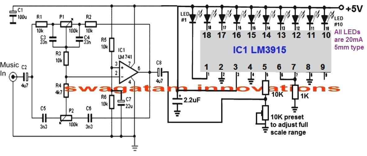
As can be seen in the figure, the circuit of the proposed audio spectrum analyzer consists of two main stages.
Circuit Operation
The left stage can be witnessed to be an active tone control stage while the right side IC LM3915 stage is a 10 stage dot/bar LED display stage.
The tone control stage is a simple bass/treble boost circuit which can be set for acquiring the intended magnitude of signal for a particular fed frequency.
This can be done with the help of the two pots.
P1 may be set for controlling the bass or the low frequency band, while P2 can be adjusted for achieving the high frequency content from the input.
The led driver stage basically responds to a DC level applied to its pin#5.
This response is converted into a sequencing to and fro movement of the LED connected at its outputs.
For example, at voltage levels around 0 and 2, the first three or four LEDs would respond creating a up/down dancing movement, the subsequent LEDs would respond in similar fashion as the input voltage rises at pin#5 of the IC.
How to Set the Controls
The active tone settings decide which frequency level is allowed to get past to the output or amplified to the output of C3.
Suppose if you adjust P1 such that only frequencies within 200 Hz are allowed to pass, the LEDs will produce maximum rise and fall only for these frequencies, and if the music content lacks these frequencies will result in a lower rise or fall in the sequencing.
Similarly you can adjust different frequency ranges for the additional channels in order to achieve the intended fluctuations over the connected LED driver output.
You can make 3 of these or may be 30 of these, just arrange them serially, adjust the pots as per the required specs and see the LED bars dazzle in a up/down motion producing a stunning audio spectrum graphic analysis.
Circuit Diagram
Parts List for the op amp stage
- R1, R2, R3, R6 = 10k 1/4 watt 5%
- C1 = 100uF/25V
- C2 = 4.7uF/25V
- C3, C4 = 33nF/50V
- C5, C6 = 3.3 nF/50V
- C7 = 22uF/25V
- C8 = 4.7uF/25V
- IC 741
Parts List for the LM3915 stage
- 10k, 1k, 1/4 watt 5% = 1 each
- 10k preset = 1
- 2.2uF/25V = 1no
- LEDs 5mm 20mA, color as per specifications = 10 nos
- IC LM3915



Questions & Answers
I real interested, but at my location Ifailed to find the main chip, LM3915, what ease can I do to decorate my homemade amplifier? Thanks a lot to U
If you want to make the above project you will have to get the prescribed ICs, no other options sorry.
you will need to put PNP transistors at the outputs of the IC LM3915, refer to this post for help:
https://www.homemade-circuits.com/2013/07/bike-generator-to-220v-converter-circuit.html
In place of the relays, you can add 1 watt leds.
good day sir, i want to make 10 band of this spectrum, where should i connect the 2nd circuit?
thanks sir.
good day ivan, you will need to make 10 of these circuits separately and feed the music to all the inputs by joining all the inputs together.
good day again sir, thank you for your reply, i have another question, will this circuit works at 150 watts or above?and should i use regulated power supply for this?
Ivan, watts is not relevant to the circuit performance, the music input voltage is only important.
The voltage should be ideally a 5V regulated DC.
thank you sir, if i connect it to a power amp and the voltage exceed 5V will it work?
If you connect more than 5V, the LEDs will dissipate more current and become warmer.
good day sir, what is the maximum music input voltage that can accept this circuit?is 1/4 watt resistor ok for this circuit?
good day Ivan, it's not critical, it can be of any level.
good day sir, thank you for your help and for the circuit, i have a last one question, how can i compute the freq?what computation should i use?
good day.
frequency calculation?? for what?
Good day sir, Is this Spectrum a passive and active filter?
Good day Abdullah, it's an active filter.
Can you please send / post a picture of the completed board(s). I need to see and read to do. Great work and thanks for sharing it!
thanks, the circuit has not been tested practically yet so at the moment I don't have the prototype images…
good day sir, how cam i compute the frequency? in every stage. (I'm going to make a 10 band spectrum analyzer)
good day faith, you will need to set it up manually, feed the desired frequency at the input and adjust the bass/treble controls such that all the LEDs light up in response to that frequency level. In the same way you may apply other frequencies to other subsequent modules and set it identically.
The sample frequencies may be generated using a 555 IC astable or any other similar oscillator circuit.
Hi sir im going to make a 16 band spectrum. Can you please send a schematic diagram a sample when you connect the two circuit for a band? For the music input sir will I use a jumper wire right after the starting capacitor after the audio jack amd connect it directly to my second circuit? Thanks sir
Hi Karl,
as per the explained concept in the above article you would 16 such modules and
connect their inputs in common and feed the music to this common lead, meaning connect all the C2 ends together and feed the music across this common end and the ground (negative terminal)
But before making 16 units it is advisable to make 3 initially and confirm the response.
….and please make sure to connect pin9 of the IC with the positive line for enabling a BAR graph response on the LEDs.
Thanks comrade 🙂
My pleasure!
Hai sir….
LM3915 using in power amplifer Decibel meter…when I'm using LED it working well.When i use Pnp transistor the pin no 11 is continuously glowing….when i use led its work very well…what's the reason…till now i can't find any solution…pls help me sir..
Hi Kesava, if only the pin#11 is glowing then your PNP could be faulty or wrongly connected….if it was pin#1 glowing then it would have made sense, but pin#11 is the second last channel in the sequence which can never glow unless something is wrong in the circuit.
Okay sir…i will check the circuit…
Transistor Base resistor shall i use 470 ohms sir ,now I'm using 1k in
BD140
the resistor cannot be the issue, the transistor itself could be faulty or connected incorrectly, by the way why are you using a transistor?
the base resistor will depend on the LED current, 1K will do..
you can connect at least 5 to 8 LEDs in series across each channel with a supply of around 24V
For each channel i'm using led strip 1 metres sir….i check the transistor ..it's good sir..base resistor connected to the pin 11 its glowing sir…whether ic is faulty sir
OK then transistors will be required….
if the transistor is good, then the IC could be faulty or a short circuit could be there near the base of the transistor or pin#11
Thank u sir ..
U helping me a lot..
Very very Thanks sir..
you are welcome!!
Sir now i check the circuit….
While using led in pin no:11 not glowing…pin no 11 voltage is 0.50.
In the same time i connected transistor…Transistor working it produce 10v….
0.50 voltage will trigger the transistor ?
In led working well. in transistor only pin no 11 not working well….
Is there any other way….Transistor is good i change it 3 times….
Kesava, how did you check the voltage?
check across the pin11 and the positive line not the negative line.
I check it like that only sir…
0.50v o/p producing in pin 11…
When i use led working good…
Only problem when i use transistor…
Is there any solution sir.
If u r using infrared photodiode circuit…pls give the link id sir
connect LED with the base of the transistor and check the response….cathode will go to the IC pin and anode to transistor base resistor.
IR circuits can be found here
https://www.homemade-circuits.com/search/label/Infrared%20Projects
Thank u sir…
I need one more circuit…
Both Ac Dc appliances..
When we connect the load….the led indicator must be ON when we remove the load the LED INDIACTIR must be off..
I try this circuit already …connecting in series..when load applied the led will glow…but it's not good…
I need differ circuit without any loss of o/p load…pls sir
kesava, you can try the concept that's I have explained below
https://www.homemade-circuits.com/2016/11/automatic-inverter-fan-switch-on-while.html
instead of the opto just use an LED
Sir,
May I use lm386 instead of lm741….
Many thanks with gratitude….
K. Kausik
kaushik, LM386 cannot be used as a tone control stage, therefore it cannot be replaced for the shown IC 741
Good morning sir,
I've some problem with bd140 . What will be the connection diagram with load when I want it to act as a switching device triggered by the output of ic4017. As output of the ic is +ive in nature and bd140 needs a -ive signal at it's base. So am I need any other component(s)…….
thanking you,
k.kausik
Hi Kaushik,
you will need to connect it in its standard PNP mode, that is emitter to positive line, base to the 4047 output through a resistor, and collector to load, the other end of the load will join with the ground.
Sir,
Actually the pnp is not working but the npn one is working fine.
As the output signal of a 4017 ic is positive by nature how will it turn on a npn transistor like bd140. Need some clarification…any help….
Thanking you,
k.Kausik
Kaushik, NPN, and PNP both will work with any logic IC.
when IC4017 generates a positive pulses tat pin is at the supply level but when it's not generating a logic high the pin is at logic 0 or connected with the negative supply line…therefore an PNP would work in this situation.
However the response will be just the opposite meaning with the PNP the output will be like a chasing negative voltage instead of a chasing positive voltage
Got it….. -:)
just for sure ,what will be the base resistor for 12v,1.5amp load(like no of leds in a channel……
Have a good night…. till tomorrow 🙂
K. Kausik
base resistance can be calculated using the following formula:
R = (Supply – 0.6)Hfe/Load Current
Hi Swag,
Building a 10 level Spectrum Analyser, with 10 identical circuits, in order to setup the correct frequencies in each circuit, where in the circuit do I put the tips of a Frequency Meter so that I can ajust both P1 and P2 to read the frequency set for each?
Best Regards.
Nélio Abreu
Hi Neilio, I think the best place to connect the frequency meter is across the 1M resistor associated with pin#5 of LM3915
Hi Swag,
Thanks.
Best Regards.
Nélio Abreu