In this post I have explained a circuit design which converts a generator low voltage output into 220V DC and produces sequencing light illuminations across many bulbs in response to increasing voltage from the generator. The idea was requested by Mr. Ken.
Technical Specifications
I am a student from Singapore polytechnic. I know you're a busy man but i have some doubts on my school project.
I am currently building a bike generator to educate the public on the importance of clean energy. If you could kindly help me that would be great!
The problem is, how do i connect 10W AC light bulbs together and make them light up one by one from my cycling generated power?
Lm3914 ic?As we are using 10V, 800 lumen LED light bulbs, we would be using 15 or 17 light bulbs. I have attached a concept sketch of our project.
I am not sure if the Charge controller and the inverter will be needed as well or do we even need a battery. The generator is a 300W DC generator.
LED light bulbs wattage is 10W. As for the generator the output voltage range is about 0-40 volts DC. I have attached the generator specifications in the mail. Please do let me know if you need any other information.
Something to take note of as well is that in Singapore our standard voltage is 230V, 50Hz.I have attached the image of the light bulb as well.
Once again i would like to express my gratitude. The world need more people like you. Helping people even if they are strangers. Keep up the spirit!
Thank you
Ken
The Design
The proposed bike generator to 220V converter circuit can be understood with the help of the following description.
As requested, the lights are required to be illuminated in sequence in response to the increasing voltage from the generator.
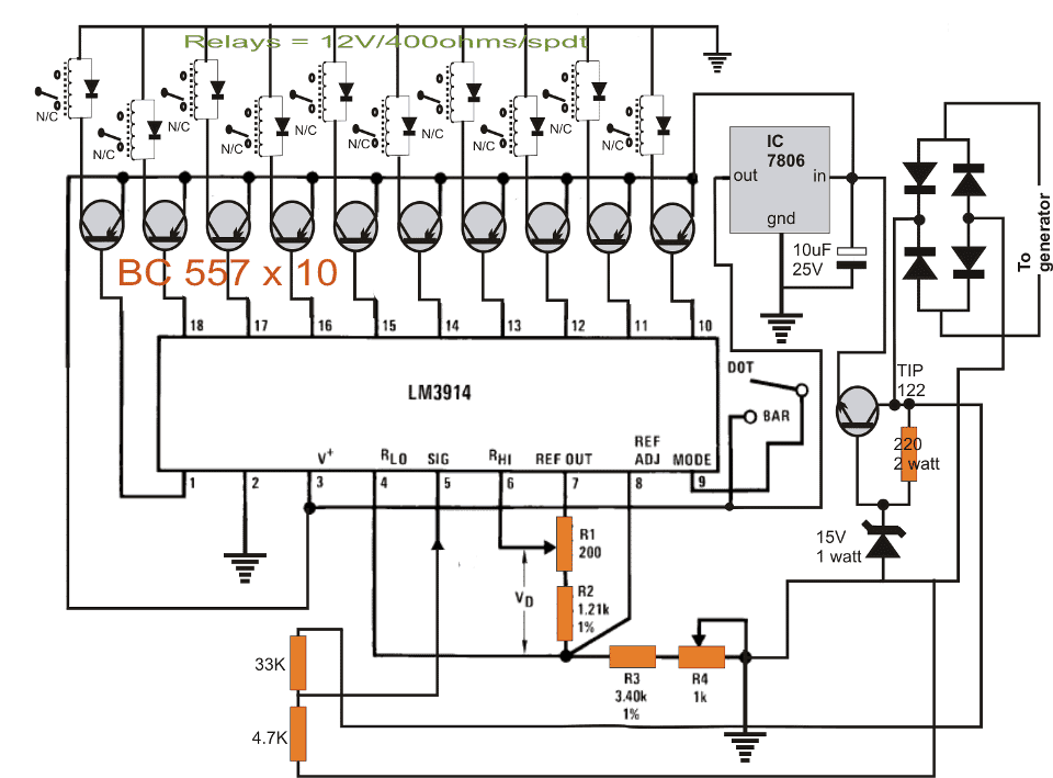
The sequencing feature is implemented by the IC LM3914 which is a dot/bar display driver chip.
The IC responds to a voltage applied across its pin#5 and translates it into a sequencing or incrementing logic high across its 10 output pins.
The outputs may be arranged to produce "dot" mode type of sequencing or "bar" mode type, depending upon the position of the selector switch connected to pin#9 of the IC.
In this design, the generator output is first reduced to 15V DC source through the TIP122 transistor stage and then further dropped to 6V which is then applied to the IC stage for the required functions.
The outputs of the IC are terminated through 10 PNP transistor relay driver stages.
The mode switch should be selected in the "bar" mode for enabling the transistors to latch up in sequence, corresponding to the increase in the voltage level and vice versa, at the input of the IC.
Since the input is restricted to receive a varying voltage from 0 to 5V, a voltage divider stage has been employed in the form of the shown 33k and 4.7k resistor which controls the voltage increment from 0 to 4.8V corresponding to the generator voltage of 0 to 36V approximately.
Understanding the generator 220V Converter Stage
The above stage only handles the sequencing function of the circuit. To light up the AC bulbs we need some means to convert the generator voltage into 220V DC.
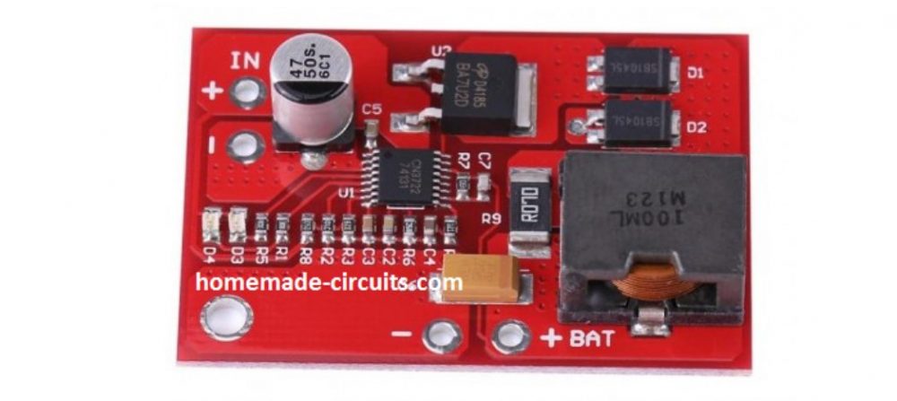
This is achieved by using a simple buck-boost network stage, as shown in the following diagram. It's a simple buck-boost converter circuit which is employed for getting the required conversions.
The figure also shows how the output from the buck boost stage needs to be wired across the relay and the bulbs which may be followed for all the relays and the bulbs.
The inductor may be optimized with some trial and error, for example begin trying with 100 turns of 22 SwG over a 10/15mm ferrite rod and measure the voltage by keeping the PWM control toward maximum duty cycle.
Then go on experimenting with the turns and the wire SWG to get the required optimized voltage for illuminating all the 10 bulbs together.

How to Set Up the IC 3914
Using a precision digital multi meter across pin#4 and 6 adjust R1 to get a potential difference of 1.20V.
Next, through a regulated variable power supply apply 4.94V to pin 5, and adjust R4 until the sequence output #10 just illuminates. The adjustments are non-interacting and set.
Generator Specifications
- Dynamo Model- 300-DC
- Output Voltage Range-0 to 40 Volts DC
- Nominal Current Rating-15 Amps
- Peak Current Rating-20 Amps
- Peak Power Output: (Charging 12V Battery ) 300 Watts (15V X 20 Amps)
- Drive Type-2" Diameter Pulley
- Peak Operating Temperature-100 Degrees C
- Cooling Method-Air Cooled
- Shaft Bearing Type-Ball Bearing
- Mounting Bolt Size-6 mm
- Wire Lead Length~12"
- Wire Lead Size-Size 12 AWG
- Approx Weight~8 Lbs
- Number of Poles (Brushes)-4
- Generator Type-This is a DC permanent magnet motor being used as a generator.
- Peak to Peak Voltage-Varies depending on RPMs
- Rated Operating Speed-2800 RPMs
- Internal Resistance-0.35 Ohms
- Typical Amp Hours during 1 hour of use~6 @12V
- Typical Amp Hours during 1 hour of use-100 Watt Hours (0.1 KWH)
A related request from one of the dedicated readers:
Dear Sir Swagatam
I am a business intern and i'm supposed to find and introduce a cool way to engage youths about Clean Energy. I saw your design on the bike generator recently and i am really interested in it.
However so, due to my country restrictions i'm unable to get materials such as ferrite rods. Hence i'm writing to you in hope that you could use this idea and come up with another circuit for me please.
The Circuit Concept:
Using the generator to make small leds light up in sequence. After which using the led to shine on photo-resistors to light up the light bulbs that should be connected to the main supply AC source 230V 50Hz.
Similar problems:I got the generator from the website that you posted.
However i tested it, and like the other ladies and gentlemen had posted their questions, mine too reached 60V+ without load.
Sir, I hope you can help me with the circuit cause i am an all business type of lady, but i do understand some simple circuit and all, but designing a circuit?
i just can't do it as professionally as you. I'd pay you to do this, but knowing that you take pride and joy in helping people in creating and learning circuits i'm afraid that might insult your honor.
I really hope that you can offer me some of your valuable time and help me with this project!
Sincere thanks,
Myla Rose
The Design#2
The requested idea may be implemented with the help of the shown modifications below.
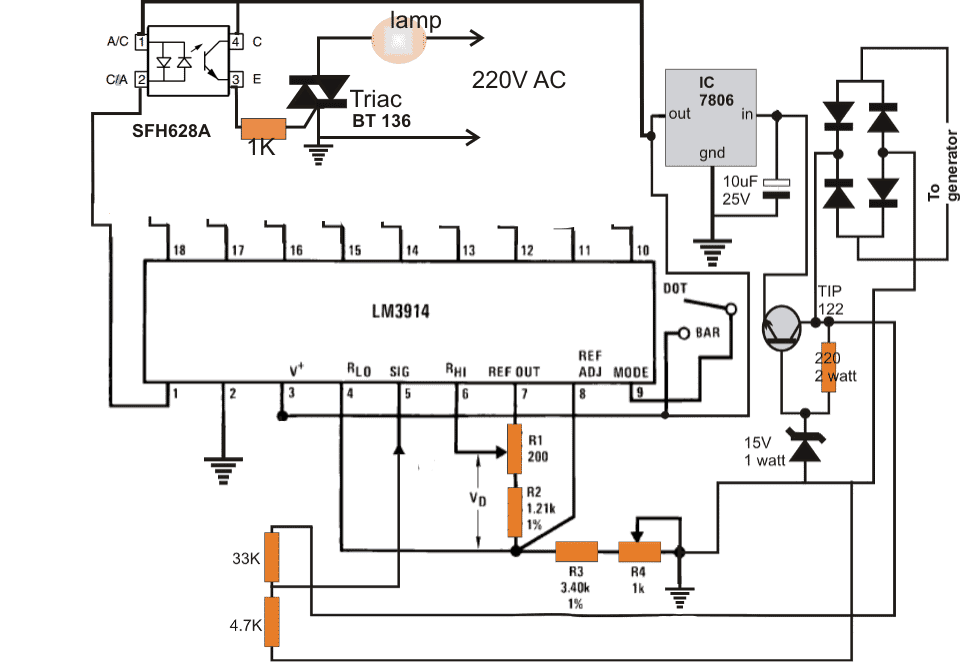
Here each of the outputs of the IC LM3914 have been replaced with an optocoupler in order to drive the subsequent triacs. Only one pinout connection is highlighted in the diagram which needs to be repeated for all the respective pinouts of the IC.
The triacs are connected with the lamps, rated and supplied by 220V mains input.
The shown opto has a bipolar input, meaning its input pins can be connected anyway round across the LM3914 outputs.
The MT2 of the triac is shown connected with the negative of the IC supply, which means the whole circuit is linked directly with mains 220V, and therefore is extremely dangerous to touch in uncovered position, extreme caution from the part of the user is thus expected.



Questions & Answers
I am sorry, I do not have any info regarding how to dimension inductors in buck-boost topologies, so can't suggest you much on this.
Here's one design which is as good, and requires no inductors at all:
https://www.homemade-circuits.com/2013/08/simple-zero-drop-solar-charger-circuit.html
You mean to say the output sequence should produce ON/OFF effect as it proceeds across the pinouts?
For that you will have to use the IC in DOT mode, simply disconnect pin#9 from the supply and keep it open.
Yes, that's perfect.
Mr Swags,
So it's like this sir?
imageshack.us/photo/my-images/854/ccmp.png/
Mr Joseph,
The TIP122, the 220 ohm and the zener diode stage needs to be completely removed, and replaced with the zero drop circuit.
TIP127 is needed only at the 10 outputs of the IC
Mr Joseph,
I have already made it clear that TIP122 cannot sustain 10 amp current and you should replace it with the solar drop circuit, yet in the diagram you have included it.
The input polarity is incorrect, it should be the other way round.
Both are good, it depends which one is easier for you to build and optimize..
Yes it can be used, however the above circuit would allow only 10 bulbs as its the maximum holding capacity of the circuit.
Please follow the steps explained in the above comments.
It's for converting AC to DC, however if the output is already DC it may be eliminated and replaced with a capacitor 100uF/100V for filtering the generator DC.
You may try other nearby values (ohms), but the wattage cannot be decreased, it has to be 2 watts or more.
The TIP122 should be replaced by the solar drop circuit, TIP122 is not capable of handling 10amps current, and therefore must be replaced with the discussed stronger counterpart.
If you can build a buck converter it would be great, you can use it here instead of the solar circuit.
Dear Sir,
Can i use this kind of ferrite rods?
singapore.rs-online.com/web/p/ferrite-rods/4674015/
2mm diameter is too thin, not suitable for the above application.
Mr. Joseph,
You can use the above shown circuit for your application.
Connect the LEDs in place of the relay coils with individual series resistor. Resistor should be 12 ohms/2watt each.
Use TIP127 for the 10 PNP transistors.
The TIP122 stage will not work for your application so you would want to replace it with the design suggested in one of the previous comments. Set its voltage to around 15V
Mr Swags,
I'm using the same generator as specified above. However when i tested it without load i could produce about 60V top. If was to use a 5W DC LED light bulb. How would i modify the circuit?
Please provide more informatiom about your application, I'll try to help.
Do you want to use the above circuit??
please provide full details about your project.
Mr Swags,
Thank you for the quick reply.
However, after dropping the 0-60V to 0-20V as LM3914 cannot support above 25V, what should i do on the LED side?
Mr Joseph,
You can try the following circuit for controlling the output voltage to any desired level.
https://www.homemade-circuits.com/2013/08/simple-zero-drop-solar-charger-circuit.html