The motion sensor circuit explained in the article works by using doppler shift principle, in which the moving target is detected through the continuously varying frequency, reflected from the moving object.
What is Doppler Effect
One very fascinating feature of sound is the Doppler effect.
The Doppler effect happens when the source that is producing the sound frequency, is moving continuously. As the moving sound source comes closer, the volume of the sound seems to be growing in frequency and volume; and as it goes away, the sound frequency and volume appear to be decreasing.
In case the sound origin is not moving, and you step toward the source or get far from the source, you experience the very same Doppler effect.
The motion detector circuit above works by using the Doppler effect to detect motion within a specified area.
A high-frequency (15 to 25 kHz) sound transmitter is targeted at the specified region, and a sensitive transducer is placed beside the source facing the same path as the transmitter's transducer.
So long as there isn't any motion within the targeted region, the reflected sound frequency and the transmitted sound tend to be with the exact same frequency.
However, any kind of movement by the target results in a small frequency change which is quickly detected by the receiver, and indicated over an attached display unit.
How the Circuit Works
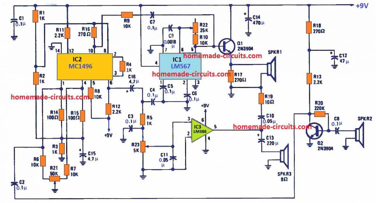
Referring to the circuit diagram above, IC1 (a 567 phase-locked loop) is set up like a tunable oscillator having an output-frequency range of 15 to 25 kHz. Potentiometer R22 is applied to adapt the output frequency of the oscillator.
The IC1 output is buffered by transistor Q1 and applied to transducer BZ1. The sound frequency reflected is captured by the second transducer BZ2, configured with the receiver stage of the circuit and applied to the base of Q2.
The boosted output through Q2 is applied to IC2 (which is connected like a double balanced mixer) at pin 1. One more sound signal (extracted from the output of IC1) is sent to IC2 at pin 10.
Resistor R21 (which is a 50k potentiometer) is employed like a carrier-balance control which is adjustable to ensure that the the oscillator's signal does not leak into the mixer output of chip IC2 at its pin 6.
The mixer's output at pin 6 of IC2 is applied via a low-pass filter on the Input of IC3 (which is built around the IC LM 386, low-voltage audio power amplifier).
A suitable loudspeaker or pair of headphones enables you to check the output from the IC3.
Potentiometer R23 is employed as a volume control.
How to Test and Set Up
Practically, nothing should be too critical about this doppler motion sensor circuit. The truth is, the circuit could be constructed simply over a piece of veroboard.
And if you build this unit over a nice and clean PCB (ensuring all the components leads are kept as small as possible), you can quickly get the desired results.
It might be recommended that you keep the receiver's input and the transmitter's output circuitry isolated from the each other, as far as possible in the construction layout, and use sockets for all the indicated IC's.
Begin the testing by the positioning of the two transducers BZ1/BZ2 (SPKR1/SPKR2) approximately at a distance of 4 inches apart, focused at the same direction, and far from any nearby objects.
Adjust the variable resistors R21, R22, and R23 to center points and switch ON power to the circuit.
If you find the transmitter's output to be audible, the oscillator's frequency may have been fixed very low. In that case, you can fine-tune R22 until you can no more listen to the frequency.
Next, tweak R21 until you achieve the most silent output on BZ1 (SPKR1).
After this, try moving your hand upward and downward in front of the two transducers (SPKR1/SPKR2), and this should cause a fluctuating low-frequency tone on the speaker (SPKR3).
As you move your hand faster, you should find the output sound frequency getting that much higher. For extremely slow moving objects, you may want to see the effect on a moving coil type DC meter connected across the IC3 output, on pin 5.
You may see the meter's needle fluctuating up/down over the scale, in response to the slow-moving object passing before the transducers.


Questions & Answers
Hie Swag.
Im sorry for bothering, my question is not related to this circuit but i need your help if you can.
I am trying to build an Elevator breakdown and maintenance mobile app that notifies a technician and other staff that the elevator has stopped.
So the issue is which sensors can enables me to achieve this setup . The sensor has to be in the shaft monitoring the movement of the lift so that when it stops for a certain preset time it will send the signal to the mobile apps that a certain elevator is stuck.
Could you assist on which types of sensor can work and also give siganl to multiple mobile app users .
Thanks
Hi Binus, I am not very sure which type of sensor would be most compatible with your application, however I think an infrared based proximity sensor might be suitable.
You can try the LM567 version of the system from the following article, and check if that works:
https://www.homemade-circuits.com/simple-proximity-sensor-circuit/
Okay thanks
About a year or two ago I was trying to develop an e-Trike controller for a custom E-Trike. It uses a 48v LiFepo4 Battery system, solar array, AC charge, and AC invert and feeds an ebike controller. I tried to rework 5 different systems you had outlined to work at 48v single battery instead of 2 by 12v batteries. while getting ready now to purchase parts to try out the designed changes I realized one resistor has no value and can’t source the transformer or know if my modified design can even drive the transformer.
Question is where can i send you the circuit layout to know if you want to help me?