The following PIR LED lamp circuit was designed by me for one of the followers of this blog Mr.Deepak upon his request.
The circuit is a LED driver which responds to ambient light as well as to the presence of a human, person or intruder, and varies its illumination accordingly, let's know more.
Technical Specifications
"I was looking to drive 20 LEDs of 0.06 watts.
So total Output voltage is 12-17 volts and total current is 0.08 amps
to drive 4 strings of 5 LEDs each
each led is 3.4 volts and 20 mA.
Can you help with this?
Also I would like to have an ambient sensor to switch on and off and a proximity sensor to switch to full brightness if some one approaches and to switch to half or 30% brightness after 30 seconds.
I need this for commercial use. I need a simple cost effective circuit. I have been following the blog and am sure that you know the subject. Please get back to me."
Simple PIR Controlled LED Lamp Circuit
Before solving the above request, let's first see how we can build the design in its simplest form using a PIR module and some LEDs.
The following circuit shows a simple PIR sensor which activates the connected LEDs in response to the presence of humans within the specified area.
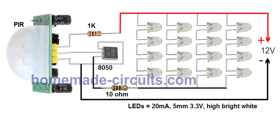
As you can see I have not used any voltage regulator here, since the 1K at the positive works good to limit the current and the voltage to the PIR. This also avoids the base resistor for the transistor.
I have used 16 LEDs, however upto 64 EDs can be used.
For the power supply you can use any cheap 12V 1 amp SMPS
Parts List for the above circuit:
- PIR Module - 1
- 1K 1/4 watt - 1
- Transistor 8050 - 1
- LEDs 5 mA, 20 mA, 3.3V - 16nos, or upto 64 nos
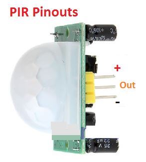
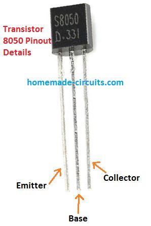
Light Intensity Transition
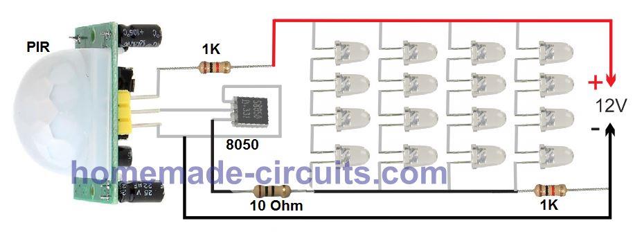
As requested, the 30% light transition in the absence of a human can be implemented by simply adding a 1K or some other calculated resistor with the negative line of the LED as shown below:
Video Demo
Design# 2
The next two PIR based sensor LED light circuits is similar but has an added feature of detecting the ambient light conditions also. Therefore the circuits will respond based on whether the atmospheric light is sufficiently dark or not and also whether the premise is occupied by a human.
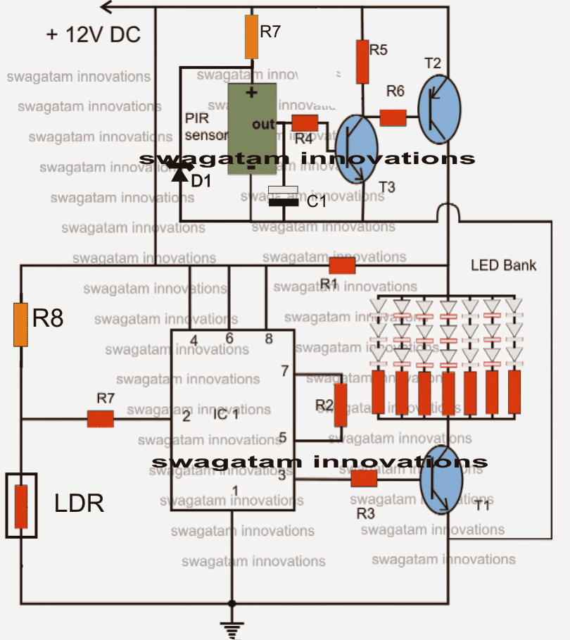
Let's try to understand the PIR based LED lamp circuit functioning from the following points:
The IC 555 is configured as a comparator, the LDR and R8 values are compared for generating an appropriate output.
As long as there's enough light over the LDR, pin#2 of the IC remains high and this keeps the output pin#3 of the IC high as well.
The high output at pin#3 keeps the transistor and the LED switched ON, until the ambient light falls below a predetermined value set by P1.
This means during night or in the absence of light the LEDs too get switched OFF.
The upper section is a proximity sensor circuit. The transistors T2 and T3 are configured as high gain amplifier and is able to sense even minute voltages from the PIR sensor.
In the presence of any human or animal in the specified vicinity, the PIR becomes active and triggers T3, which in turn switches ON T2.
T2 instantly shorts R1, such that the supply voltage reaches the LEDs directly instead of via R1.
This situation brightens up the LED illumination, indicating the presence of a passer by (as stated in the request).
The capacitor C1, ensures the LED brightness stays alive for many seconds, even after the PIR is deactivated.
Parts List
- R1 = 100 Ohms,
- R2,R4 = 100K,
- R3,R5, R6 = 10K,
- R7 (at IC 555 pin2) = 2M2,
- R7 at PIR positive = 10K
- R8 = 2M2,
- C1 = 470uF/25V
- LED resistors = 100 Ohms each,
- T1, T3 = BC547,
- T2 = BC557,
- D1 = 4.7V zener
- LDR = any standard type.
- PIR sensor = any standard type.
- IC1 = 555
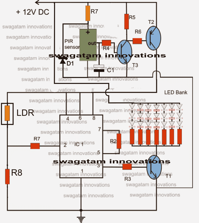
Darkness Activated PIR Circuit
The following circuit can be used for automatically detecting human presence, and activating the lights during night time.


Questions & Answers
"The high output at pin#3 keeps the transistor and the LED switched ON, until the ambient light falls below a predetermined value set by P1."
Where is P1?
Why would anybody just want the LED's to just come on during the day?
I recently changed the diagram, R8 has taken the place of P1 whose value does not need to be varied now.
The circuit is intended to be used in closed rooms during day time when its occupied by people and to be switched off automatically after dark when probably the place is closed.
The circuit just needs to be understood and tweaked as per individual preferences.
explain it elaborately and with complete details
Hii Swagatam,
I implemented your circuit with LDR & 555 IC, but my LED's are not glowing (Day & night both).
SImple PIR sensor circuit is properly working.
But when i connect IC & LDR circuit as shown above i am not getting high signal at Pin 3.
LDR resistance is around 1.5K in day time & 20K in night time.
Hi Robin,
the value of R8 must be lower than the LDR value at night, only then the LEDs will light up.
you may replace R8 with a 10k preset and set it accordingly.
sir good day will the simplified version able to power a 12v 15 watts led spotlight?
thanks
Hi aureliano, yes it will.
Hai, how to connect another PIR sensor in the above circuit??
Bcoz I need a circuit like this :- circuit should contain two PIR sensors and one LDR sensor. The LEDs always should be in OFF state only. If a person cross any one of the PIR sensors means the LEDs should iluminate for 60 seconds and then it should OFF. During day time, if a person cross any one of the PIR sensors means the LEDs should not iluminate. How to control this with LDR??
And how to add a manual switch to the circuit to turn ON the LEDs manually??
Pls help… Am trying to make a circuit for my house staircase..
Hi, you can connect another PIR parallel to the existing one, just put diodes at the output pins of each PIR.
The 555 is placed exactly for the same that is for daytime inactivation of the LEDs, in the second diagram.
for 60 second delay, you will have to incorporate a 555 monostable…i will tell you about it more after you finish the above stages.
Hello sir, Could you tell me how to connect another PIR sensor in the circuit?? So if I walk across any one of the PIR means the light should iluminate. And according to the datasheet of PIR sensor, the input voltage for PIR should be 3.3 – 5v DC. But u connected the PIR with 12v. Will it wont fry the PIR module??
Hello, yes you are right it must connected through a 7805 IC, I'll make the changes soon.
connect the two PIR (+) and (-) in parallel and terminate their output pins through individual 1N4148 diodes….anode of the diodes will do to the outputs while the common cathodes of the diodes can be connected to the above circuit (to R4)
Hai, here is the diagram..
imgur.com/rLfrnRh
check wheather the PIR and diode placement is correct. And then can I give a input of 5v instead of 12v?? And I like to replace a 5v relay instead of LED bank. Is that possible?? shall i replace 10k preset instead of R8?? so i can adjust the sensitivity of the LDR.
yes that's fine.
you can use 5V for the entire circuit or only for the PIR while using the 12V for the remaining circuit so that a 12V relay can be used.
replace R8 with a 100k preset.
Hai, I am modifying the third circuit as follows:-
I am giving input power supply as 5 volt dc , replacing LED bank with 5 volt relay, R8 as 100k preset.
Then if a person pass through the sensor means the relay should be ON state for 60 seconds.Then it should get OFF. what I have to modify for that?
And if there is ambient light means , If I pass thorugh the sensor means the relay should not get ON. The relay should be in OFF state only. what I have to modify for that??
Hi, you will require a monostable circuit using IC 555, R3 and T1 won't be required since you are using a relay.
Connect the monostable pin2 with pin3 of IC1 and connect the relay directly either across pin3/positive or pin3/negative of the monostable.
Set the monostable timing capacitor/resistor for acquiring 60 seconds
what is the value for the T1, T2, T3 , C1 for the third circuit diagram?? U mentioned different values in two parts list. And R1 is missing in third circuit. Do I need R7 resistor which is connected with the PIR?? Bcoz i am giving the power supply as 5 v only know. so I am confused. I am giving the power supply as 5v. so do i need to reduce values for all the resistors?? If possible means can u pls tell me the whole parts list for the third circuit diagram??
the parts of the last circuit are same as the first one.
R1 is provided for a different application need, please read the circuit description for the first design
ok thankyou. Am using power supply as 5v , so is that R7 at PIR is required?? and Do i need to decrease the values of all the resistors and capacitor??
no R7/D1 won't be required if the supply is regulated to 5V….the same circuit should work for 5V also, no changes would be required.
ok. how to manually ON the relay to ON the light?? Is that possible by connecting spdt switch?? Like, switch UP means censor, centre means total OFF, down means manually ON the light. If possible means how to connect?
you can do it by connecting the spdt in parallel to the relay contacts which are responsible for switching ON the LEDs
you may connect the relay directly to pin3 of the monostable
Hai, One doubt. As I want the relay to be in active state for 60 seconds if the PIR detects the motion, U suggested me to include a monostable circuit for that. But U mentioned in the article that "The time for which the LEDs remain ON is determined by the product of R4 and C1". This wil keep the LED bank ON for 51 sec. Instead of LED bank and removing R3,T1, if I connect a relay directly to the pin3 means ,the relay wil be in ON state for 51 sec. So still do I need a monostable circuit??
Hi, please show me with a diagram so that it becomes clearer to understand.
A 555 monostable will give much accurate and well defined timing response, so it's recommended.
I got a new PIR sensor. It is mentioned that the operating voltage is 4.5-20v. so If i use this PIR in ur circuit means do I need D1 and R7 at PIR??
And Can I connect the 12v relay directly to the pin3 of IC by removing R3 and T1 ??
D1, R7 can be eliminated for a 5 to 20V PIR device.
yes if a relay is used it may directly connected with pin3 of 555
I added a monostable circuit in the bottom left side.Though I am using monostable circuit, do I need the 470uf capacitor and 100k resistor at the PIR??
470uF may be reduced to 10uF/25V or any other lower value, R4 is a must and cannot be removed but 100k is not critical, other values will also work
what should be the minimum and maximum current need for the third circuit??
minimum current should be 150mA, maximum is not important it can be anything.
After including the monostable circuit to the above and setting the capacitor and resistor for obtaing 50 seconds. Suppose if I walk through the PIR means the monostable circuit start counting for 1-50 seconds. Suppose if I walk thorugh the same PIR at 35th second means will the counting start from 1-50 or not?? If not means how to modify the circuit for restarting timer??
connect pin4 of the monostable to positive via a 10k resistor and also connect this pin with collector of T3 via a 0.22uF resistor.
Thankyou… I did as u said. Check whether this is correct…
imgur.com/fDespFa
So this will restart the timer of the monostable every time when the PIR detects the motion. Am i correct??
yes it's correct.
I am assuming it would work in that way, it will need to be confirmed practically.
Dear Mr. Swagatam.
In your 1st circuit diag when the leds are powered via R! they just work at lower voltage but no power is saved as it is consumed by the resistor, so this design can be modified a little to actually save power.
Also i have one question. Just by interchanging the positions of LDR and R8 can this circuit switch on when it is dark n switch off when there is light?
Dear kkaranjia, you can replace R1 with 3nos 1N4007 series diodes for saving energy.
yes interchanging LDR and R8 will reverse the response, please see the last diagram.
Dear Swagatam,
I have an other option of using either 1,2 or 3 string on direct supply without R1 and rest all strings through T2. This will just just keep 1,2 or 3 string when no human is detected and switch on other strings when human is detected.
Dear kkaranjia,
you can try the second circuit, simply add a TIP122 base through 10k resistor with the collector of T3, connect the LEDs across its collector and positive….emitter will connect with the ground.
Hai, I made the third circuit and some problems in that. The circuit is working as "If there is ambient light in the room means, the output at the pin3 of IC1 is low. and if the room is dark means the output at pin3 of IC1 is always high". Means The output at the pin3 should go high when the room is dark and if anyone moves infront of the PIR. But the pin3 of the IC1 is high when the room gets dark itself. The PIR is not working in the circuit itseems. I checked the PIR seperately and its working good. Dont know where is the problem.
And I added a monostable circuit by connecting the pin3 of the IC1 to pin2 of the monostable circuit. Here also a problem. If the pin3 of the IC1 goes low means the monostable circuit IC is getting very hot and fried. Pls give me solution…
If the PIR does not respond T2 will not conduct and the IC555 will not get any supply so how can its pin3 become high in darkness???
Separate the stages completely and check them individually
T2 should conduct only when PIR detects a human presence otherwise not.
Pin2 of the monostable will have a very high resistance so how can the other 555 become hot???
You might have done something wrong in the connections… check it properly or make the design step wise.
Hai, now the circuit is working good. The problem was with the conections.so when the PIR detects a motion, the output from the pin3 of IC1 is positive high. And thn i made a monostable circuit. The pin2 of the monostable needs negative to activate a relay when pin2 is triggered. so can I connect a BC547 at the pin3 of IC1 by base to pin3 via 10k, emitter to negative and collector to pin2 of monostable circuit?? pls check the diagram imgur.com/USXpBSA
And one doubt, the LDR is slightly getting hot when light is falling on the LDR. Is that normal or connection prob??
OK, fine.
The BC547 connection with the ICs is correct in the shown diagram
The LDR should not become even warm. What have you used for R8?? If R8 is very low, LDR will start getting hot. use 1M for R8
sir i try to make the second circuit i used HC-SR501 PYROELECTRIC INFRARED PIR MOTION SENSOR DETECTOR MODULE if i connect one led to out put pin is working for sen if i connected to the circuit i like to make pir sensor to on/off relay kindly asst me thank you
Satish, you can just remove the LED bank and replace the points with a 12V relay coil.
make sure you have a 1N4007 flyback diode connected in parallel with the relay coil
thank for the replay its working
i have the old circuit (without the zener and a 470uF cap) in operation, should i have any concerns, is it going to burn down my garage? why the changes in the circuit? thanks.
if the PIR is rated at 12V then the zener may not be required otherwise the PIR could get damaged.
the 470uF is for producing a delay-OFF effect, it' not a crucial element in the circuit.
also, the simplified version of the circuit has T2 (bc557) and T3(547) different than the circuit with the 555 timer. is this by design or just a typo?
thanks. keep up the good work!
Thanks for pointing that out, yes it is a typo…i'll correct it soon
can you please explain how this can become operational by solar power? thanks