The post comprehensively discusses the the similarities and difference between mosfets and BJTs and also their particular pros and cons.
Introduction
When we talk of electronics, one name becomes extremely related or rather common with this subject and that is the transistors, more precisely the BJT.
Electronics is in fact based on these outstanding and indispensable member, without which electronics might virtually cease to exist. However with advancements in technology, mosfets have emerged as the new cousins of the BJTs and have of late taken the center stage.
For the many newcomers, mosfets can be confusing parameters compared to the traditional BJTs, simply because configuring them requires critical steps to be followed, not adhering to which mostly leads to permanent damage to these components.
The article here has been specifically presented with a view to explain in simple words regarding the many similarities and differences between these two very important active parts of the electronics family, and also regarding the pros and cons of the respective members.


Comparing BJTs or Bipolar Transistors with Mosfets
All of us are familiar with BJTs and know that these basically have three leads, the base, the collector and the emitter.
The emitter is the exit route of the current applied to the base and the collector of a transistor.
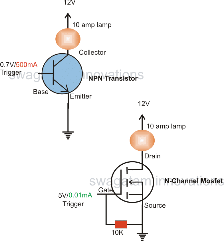
The base requires in the order of 0.6 to 0.7V across it and the emitter for enabling switching of relatively higher voltages and currents across its collector and emitter.
Though 0.6V looks small, and is pretty much fixed, the current associated needs to be varied or rather increased in accordance to the load connected at the collector.
Meaning, if suppose you connect an LED with a 1K resistor at the collector of a transistor, you would probably need just 1 or 2 miiliamps at the base for making the LED glow.
However, if you connect a relay in place of the LED, you would require more than 30 milliamps at the base of the same transistor for operating it.
The above statements clearly proves that a transistor is a current driven component.
Unlike the above situation, a mosfet behaves entirely in the opposite way.
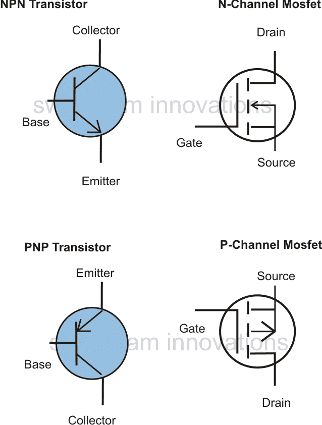
Comparing the base with the gate of the mosfet, the emitter with the source, and the collector with the drain, a mosfet would require at least 5V across its gate and source for enabling a load to be switched fully at its drain terminal.
5 volts might look massive compared to the transistor's 0.6V needs, however one great thing about mosfets is that this 5V works with negligible current, irrespective of the connected load current, meaning it doesn't matter whether you've connected an LED, a relay, a stepper motor or an inverter transformer, the current factor at the gate of the mosfet becomes immaterial and may be as small as a few microamps.
That said, the voltage may need some elevation, may be upto 12V for mosfets at their gates, if the connected load is too high, in the order of 30 to 50 amps.
The above statements shows that a mosfet is a voltage driven component.
Since voltage is never a problem with any circuit, operating mosfets becomes much simpler and efficient especially when bigger loads are involved.

Bipolar Transistor Pros and Cons:
- Transistors are cheaper and does not require special attentions while handling.
- Transistors can be operated even with voltages as low as 1.5V.
- Have little chance of getting damaged, unless something drastic is done with the parameters.
- Require higher currents for triggering if the connected load is bigger, making it imperative for an intermediate driver stage, making things much complex.
- The above drawback makes it unsuitable for interfacing with CMOS or TTL outputs directly, in case the collector load is relatively higher.
- Have negative temperature coefficient, and therefore requires special care while connecting more numbers in parallel.
MOSFET Pros and Cons:
- Requires negligible current for triggering, regardless of the load current magnitude, therefore becomes compatible with all types of input sources. Especially when CMOS ICs are involved, mosfets readily "shake hands" with the such low current inputs.
- These devices are positive temperature coefficient, meaning more mosfets can be added in parallel without the fear of a thermal runaway situation.
- Mosfets are comparatively costlier and needs to be handled with care, especially while soldering. As these are sensitive to static electricity, adeqaye specified precautions become necessary.
- Mosfets generally require at least 3v for triggering so cannot be used for voltages lower than this value.
- These are relatively sensitive components, little negligence with the precautions can lead to an instant damage to the part.

This is awesome, thanks very much.
You are welcome!
Very well explained as always!
My pleasure Vasilis!!