Mosquitoes are a big menace to humankind and these are present in every corner of the world. A cool way of avenging yourself could by eliminating these "devils" through electrocution. A mosquito swatter bat is designed just for this. I have explained how to build its electronic circuitry. The idea was requested by Mr. kathiravan d.
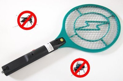
Mosquitoes can be Hard to Eliminate
Mosquitoes are tiny in size but they come in big numbers, and no matter how much we try to eliminate them, these micro pests keep growing with their population.
Today you will find plenty of techniques available in the market that provide us with the options of getting rid of these insects, some are in the form of sprays, some are in the form of coils and mats that need to be burned. Most of these variants are chemical based which either drive away or kill pests due to their toxic nature.
Needless to say if these chemicals have the potentials of harming the pests they would do the same to us in a smaller scale, but nevertheless in the long run they could cause significant health hazards.
Update: Want to know how to build a simple mosquito killer bat without any circuit or battery? Learn More
Audio/Video Representation
Using Swatter Bat for Killing Mosquitoes
However there's an innovative method of killing mosquitoes by electrocution which doesn't involve chemicals and also the procedures are clean, without any mess.
Moreover the electrocuting equipment being in the form of a tennis racket makes the swatting playful and provides an opportunity to avenge ourselves from these pests.
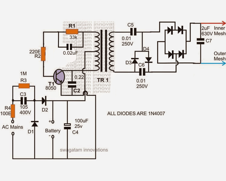
The proposed mosquito swatter bat or mosquito zapper circuit can be seen in the diagram given below, the functioning may be understood with the following points:
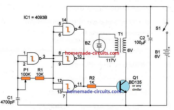
The shown configuration employs a blocking oscillator concept as used in joule thief circuits, wherein only a single transistor and a center tapped transformer execute sustainable oscillation across the two winding of the transformer.
How the Circuit Functions
R1 along with the preset and the C1 determine the frequency of oscillation. R1 ensures that the transistor never comes within an unsafe zone while adjusting the preset.
TR1 here is a small ferrite core transformer built using the smallest EE type of ferrite core.
The winding inside the coil is calculated for working with 3V DC supply, meaning the circuit becomes compatible with a 3V battery pack made by putting a couple of AAA cells in series.
When power is applied to the circuit, the transistor and the center tapped transformer instantly start oscillating at the specified high frequency. This forces the battery current to pass across the TR1 winding in a push pull manner.
The above switching generates a proportional induced high voltage across the secondary winding of TR1.
As per the winding data, this voltage could be somewhere around 200V.
To further enhance and lift this voltage to a level which may become suitable for generating a flying spark, a charge pump circuit involving a Crockcroft-Walten ladder network is used at the output of TR1.
This network pulls the 200V from the transformer to about 600V.
This high voltage is rectified and applied across a bridge rectifier where the voltage is appropriately rectified and stepped up by the 2uF/1KV capacitor.
As long as the output terminals across the 2uF capacitor are held at some specified distance, the stored high voltage energy inside the capacitor is unable to discharge, and stays in a standby condition.
If the terminals are bought at a relatively closer distance (about a couple of mm) the potential energy across the 2uF capacitor becomes capable enough to break the air barrier and arc across the terminal gap in the form of a flying spark.
Once this happens, the arcing momentarily stops, until the capacitor charges fully to execute another spark, and the cycle keeps repeating as long as the gap distance is kept within the saturable distance of the high voltage.
When this circuit is applied as a mosquito swatter, the end terminals of the 2uF capacitor are appropriately tied or connected across the internal and the external bat mesh layers.
These metal mesh layers are woven and positioned tightly over a sturdy plastic frame in such away that these are held apart at some distance. This distance prevents the high voltage spark from arcing across the meshes while the bat is in a stand by condition.
The moment the bat is swatted over a fly or a mosquito, the insect gets bridged itself between the bat meshes and allows the high voltage to find and easy conducting path through it.
This results in a crackling sound and a spark through the insect, killing it instantly.
Making the Ferrite Core Transformer
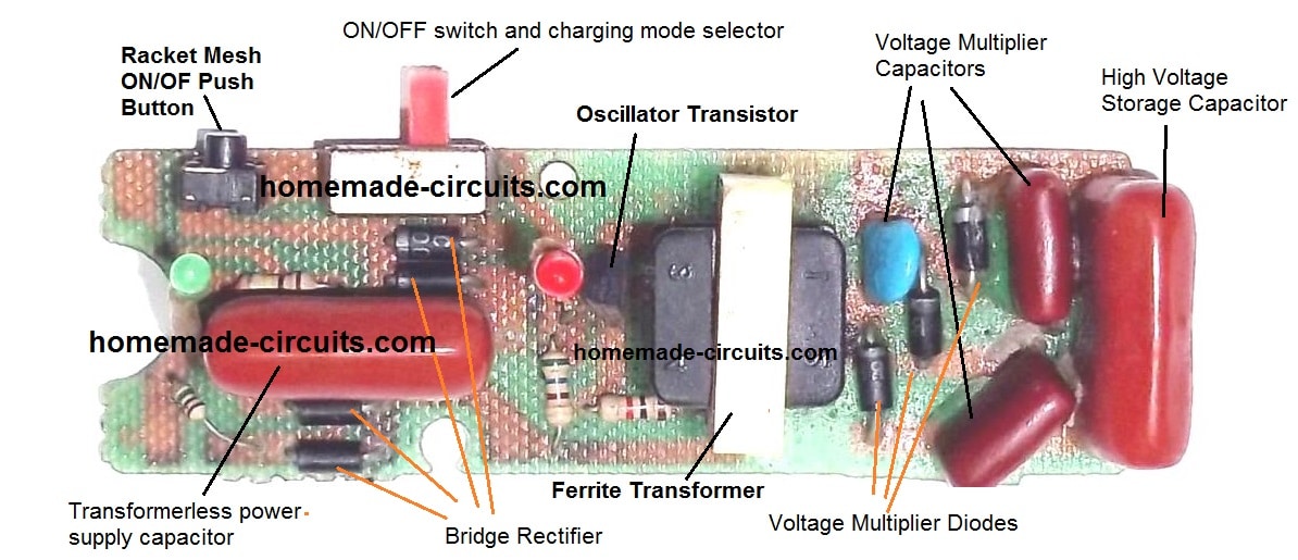
The circuit of the mosquito zapper explained here also includes an small transformerless charger circuit which may be connected to mains for charging the 3V rechargeable battery when the bat stops generating sufficient arcing voltage while swatting the mosquitoes.
TR1 winding details can be found in the following image:
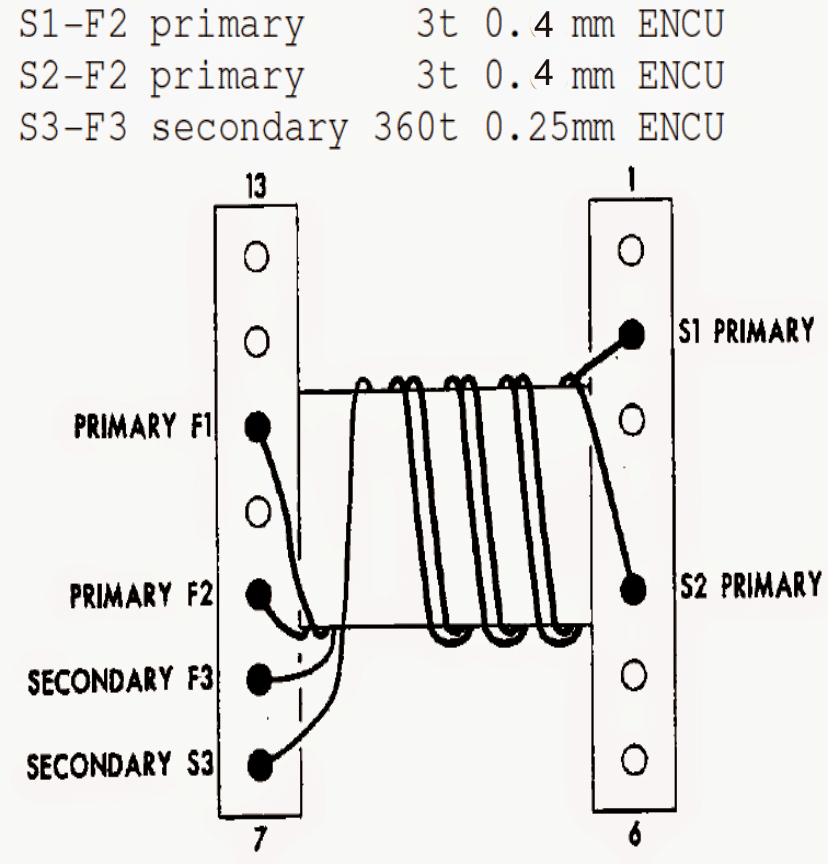
Core: EE19/8/5
Interested to know how to Repair Mosquito Rackets?
Commercial Mosquito Zapper Circuit
The following section discusses the construction details of a high voltage generator circuit which are normally used inside all Chinese or commercial mosquito zapper or mosquito racket units.
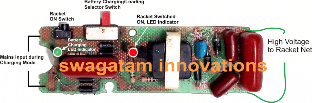
In one of my earlier posts I discussed a simple mosquito zapper circuit, in this article we study a similar design which is commercially used in all mosquito rackets, or mosquito bat units.
How this electronic mosquito racket circuit works
The article was originally posted in one of the Chinese electronic sites and I found it quite interesting and an easy design, and therefore decided to share it here.
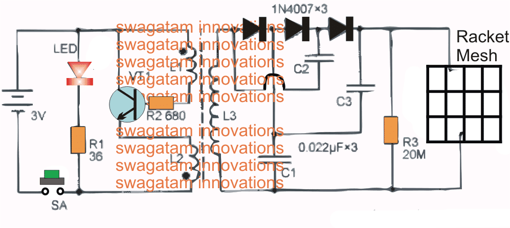
Parts List
- All resistors are 1/4 watt unless specified
- R1 = 36 Ohms
- R2 = 680 Ohms
- R3 = 20 Meg Ohms
- All Capacitors are PPC Type 630V
- C1, C2, C3 = 0.022uF
- Semiconductors
- VT1 = 2N2222 or 8050 Transistor
- D1, D2, D3 = 1N4007 Diodes
- LED = RED LED 20 mA 3mm
- Miscellaneous
- Push Button switch, micro-switch
- 3V or 4V rechargeable Battery
When the power switch SA is pressed, the high-frequency oscillator composed of the transistor VT1 and the step-up transformer T is energized using the 3V DC supply generating a high-frequency alternating current of about 18kHz, boosted by T to about 500V.
This high voltage ranging at 500V is then further stepped up using a ladder network, which is made up of three 1N4007 Diodes, capacitors C1- C3.
This network steps the T output to approximately three times its original value and we get around 1500V which gets stored inside a high voltage PPC capacitor positioned at the extreme end of the ladder network.
This stepped up 1500V is then terminated to the mosquito racket net, which now becomes armed with this high voltage and when ever a mosquito tries to get past the racket net, it instantly gets electrocuted through this high voltage discharge from the PPC capacitor.
An Led can be seen included in the design, it is used for indicating the ON/OFF states of the circuits and also the how much power is left inside the battery. The series resistor R1 decides the intensity of the LED which can be tweaked as per preference to maximize battery life
Component selection
The oscillator transistor used in this Chinese mosquito zapper circuit is a 2N5609, which is an NPN BJT, having a current handling capacity of around 1 amp, however other similar variants such as 8050, 2N2222, D880 etc can also be tried instead of the original number in the design.
The LED can be any 3mm tiny 20mA type of LED, the diodes can be 1N4007 type although fast recovery would work much better, therefore you can also try replacing them with BA159 or FR107 type of fast diodes. The resistors could be 1/8 watt rated or even ¼ watt can be used without issues.
The capacitors must be strictly PPC types rated not less than 630V.
How to Build the High Voltage Transformer
- This is ideally constructed using a 2E19 type ferrite cores and the respective matching plastic bobbin.
- L1 consists of φ0.22mm enameled copper wire or magnet wire with around 22 turns
- L2 is identically wound using φ0.22mm enameled copper wire or magnet wire with around 8 turns
- Finally, L3 which constitutes the secondary winding uses φ0.08mm enameled copper wire and has around 1400 turns.
The above discussed mosquito bat circuit can be also used for killing various kinds of bugs through electrucution using some other suitable format. For example this design could be integrated with a mesh over a dish having a mosquito/bug bait, which might attract the mosquito/bugs and eventually electrocute them as soon as they try to enter the dish through the electrified mesh.
Warning: The above design is not isolated from mains input voltage and therefore will be floating with lethal mains AC, the user is advised to exercise extreme caution while handling or testing the circuit in open and powered condition.


Questions & Answers
dear sir your work is beautifull i have a question i am from pakistan and there is alot of outage of power in pakistan i have a laptop which requires 19 v and i have hdd sata which need +12v,+5v
i mean i need 19v 12v and 5v from 12v battery i brought 12 to 220 dc to dc 120w converter now i need to have these three different dc volts kindly help me
regards.
Dear Raja,
For getting 19v voltage from a 12V batt, you can try the following circuit:
https://www.homemade-circuits.com/2013/03/charging-laptop-from-car-battery-dc.html
12V can be directly acquired from the source, while 5V can be gotten by employing a 7805 IC.
kathiravan @ swagtam sir .thank you sir . i will ask doubts if any arises sir . thank you very much sir. one question is the circuit tested already and working .or do i have to check it sir.
Kathiravan, I had tested it using an iron core transformer, and it had worked…but I am not sure how a ferrite core transformer would do. You will have confirm the results with some trial and error.
sir , the type of capacitors was not mentioned in the schematic because x rated capacitors and ceramic capacitor are commercially used.please give details about capacitor c1 upto c7 for capacitor c7 you have mentioned in article as 2microfarad and 1kv rating but in diagram 630v .is it x rated capacitor. you have said R1 along with preset and c1 determine oscillation and also adjusting preset. i dont get that sentence meaning sir .
All capacitors are metallized polyester type for better performance.
R2 (not R1) can be replaced with a 1K preset for optimizing the best frequency from the circuit.
2uF can be 630V or 1kv both will do, 1kv would be better.
sir , i am not getting capacitor c1 and c2 also c5 & c6 in my area any alternative values sir. give me some idea about selecting values sir.
kathiravan,
the values are very standard and common, if you are not getting them then i am afraid you cannot build this circuit
ok thank you sir. i will try.
Sir i have bought the transformer core,but the shopkeeper don't understand the size mentioned above, he gave the core look like the transformer used in readymade swatter bat.
does the size of the core effect the working of the bat?
Syed, I think it should work, but I am not absolutely sure…you can give it a try,
thanks sir…
i have a question that:
0.4mm=27 SWG
0.25mm=33 SWG
is it correct?
Sir plz explain the winding manner as you have mention in your other posts.I am in trouble with s1 s2 s3..
Syed, I am not very sure about it, please refer to an online "SWG to mm" converter site, you will get the required info immediately.
Thanks sir.
hello sir i have made this circuit and the output is about 65v.
is it working properly or not?I want to confirm about the working of the circuit…
hello Syed, the voltage across the transformer secondary must be at least 300 to 600V….how many turns have you used for the secondary?
increase it to 500 turns and check.
i have used a readymade transformer i don't know the no. of turns but it is very bulky.
i have wound the primary myself ..
there is no space for more secondary turns.. 🙁
the output voltage will depend on the secondary turns, each turn will roughly produce 1V, so at least 500 turns would be required at the secondary.
since a 3 or 4.5 V would be used the wire gauge should be extremely thin, about 36 SWG or less than 0.2mm
sir you have mentioned above that you have tested the circuit with iron core transformer.
sir can give me the information about the iron core transformer.
i Have tested with ferrite core but the output does not increase than 100v
if you are using a 3V or a 4.5V DC supply then you can try any 3-0-3V/220V step down transformer, but iron core trafo will not produce a good spark at the output.
If I use 3V or 4.5V DC supply then what which "Capacitor VALUE" should I use ?
capacitor value will not change but R1 might need to be reduced to 10k or less.
sir can u please tell me in detail how does the transistor and center tap transformer works in the racket
it's a blocking oscillator type of circuit, if you study how a blocking oscillator works you will understand the above concept.
Sir can i use the output of the mosquito bat circuit as input voltage to glow LEDs connected in series/parallel.
If Yes
how many 1W LEDs can i glow.
what resister to use with each LED
howmuch backup
Chetan, why do you want to use this circuits for the LEDs, why not use the LEDs directly with the battery??
i thought i can use the rechargable unit available in this circuit as it is and give the output to leds
you can connect the LEDs directly across C4…no need of making the rest of the circuit.
That is a cool idea sir, thank you… can i use the same circuit till C4 with more number of AA rechargeable batteries.. i would like to use around 4 AA or one 9 volts battery.. could you help me with the circuit for 4 AAs / 9v cell till C4…. and if possible any indication circuit for Battery charge full… Thanks again for your kind replies and help.
for charging batteries a capacitive power supply is never recommended so I won't recommend this circuit for a regular charging of batteries, it may be used for trickle charging only in compact units, but not for standard charging operations….because the supply is not regulated and the entire circuit may be hanging with dangerous mains voltage that can kill you if touched in powered position.
why don't you use your cell phone charger for the same? it's by far the safest idea and an effective one too.
indication can be achieved by using an opamp circuit in between the power and the batteries…
Hi sir this is Naveen, i have rechargeble mosquito bat, but it's not working.
i understood the circuit, but the battery was gone.i measured the voltage across the battery terminal it was showing 220v dc and its coming out from bridge rectifier.is it possible to charge a battery with 220v dc and how much battery voltage should i replace.please help me out regarding this issue.
Hi Naveen, the 220V that you are able to measure must be very low in current, which is supposed to drop to the battery's specified voltage level once connected….but anyway for ensuring maximum safety you could attach a 12 zener diode across it and check the response….it should come down to the zener level if everything's right.
after that you can configure the battery with the output.
most probably the battery should be a 3V rechargeable kind of battery.
the output could be without isolation from mains and extremely dangerous….I hope you are aware of this.
can I use a the TR transformer of an old non working swatter unit, sincei found it dificult for me to make my own xformer myself?
you can try that, if the principle used is similar then it might work….
Hi Swagatam,
I have mosquito racket which I bought from market , now it's battery is out of order, I opened it and it has unbranded battery and having no name, the number mentioned on it is HX-135 , which is 100% wrong because this number belongs to car batteries whereas this is very small battery. Could you please let me know how much volt battery (rechargeable) should I install in it and from where can I get that. If you wish I can show you photo of this battery which was in mosquito racket.
Any help much appreciated.
Thanks
Hi Franky, the battery used in Mosquto swatter batts are mostly a couple of rechargeable AAA cells in series….these are usually sealed inside a plastic sleeve. you can also try a 3.7V Li-ion cell for the same…an electronic part retailer will have a better idea about it.
Thank you
Hi sir, is it possible for me to replace the above transistor with tip42c or 41c. And what is the type of transistor present in the circuit above(PNP or NPN). Thank u
Hi Tun, yes that's possible.
it's an NPN
TIP42 will not work, TIP41C can be tried
Hi sir, i forgot to asked what AC mains mean in the circuit above
Hi Tun, please ignore the AC power supply circuit
or you can refer to the following circuit, and do it as per this circuit:
https://www.homemade-circuits.com/2014/06/mini-fence-charger-circuit.html
sir, can show me how to build a mini welding machine, just for home use. thank u
Hi Tun, I have an idea in my mind, I'll let you know soon through a new article.
thank you sir, I'll be waiting for your reply sir
Tun, I have posted it here:
https://www.homemade-circuits.com/2016/05/mini-welding-machine-circuit.html
respeted sir
plz tell the value of r1,vr1 and t1 value of given circuit in that link
1.bp.blogspot.com/-vXhsL6jBbHo/U6BT9zYFKfI/AAAAAAAAHPw/SX33Sz5sNe0/s1600/high+voltage+geneartor+circuit.png
Sagar, R1 can be a 1K resistor and VR1 can be a 10k pot
sir what type t1 i can use in that circuit
any NPN rated at 1 amp
respected sir i am having trouble getting the transformer mentioned above can u please give me a standard easily available transformer to replace tr1 with . thank you
Mahesh, if you can get a ferrite rod, then you can try it as the core for the coil, first wind the secondary turns and then insulate it with PVC tape and then wind the center tap primary over it…secure both the winding with glue feviquick.
It would be great if you can make a post of the whole process of making the Coil. Getting that coil in the market is impossible . I wasted a lot of time. I gave up repairing the Swatters just for this reason. BTW great post. I love all the information you provided. Thanks a lot BRO
Thank you, I’ll surely try to update it soon, within a couple of days.
what is the simplest way to increase output voltage
without the coil it's not possible.
I m making complete mosquito circuit by using software (Proteus).if i m applying voltage (6v) then getting output of value 17v ..
And here u r assiging value to every capacitor and resistance in category of voltage ..how can I do it?
Facing problem about voltage in complete circuit.totally puzzle .
Help me plz
Thnx advance
sorry I cannot troubleshoot a software's interpretation…it's better to build it practically and then tweak the results for getting the best possible outcome.
Hi Syed
Please let me know that which valtage rated rechargeable battery is used in mosquito bat
Hello sir , it,' s very glade to read your information given on mosquito bat, sir, please tell me one thing , my bat not sparking properly as it applies the sparks across the mesh, so what is the basic fault, and how can i repair it.
hello, thank you!
if its sparking across the mesh it could be due to a wrongly aligned mesh…make sure the distance across the whole mesh assembly is uniform and not depressed or twisted somewhere…or else the spark will tend to fly across these points where the distance may be minimum…
After removing the rechargeable battery and putting in ac currcurrent i am getting any spark but on adding rechargeable battery no spark is generated.battery is in well condition.plz help.
if it's working with mains ON and not with battery connected, then definitely your battery is not good or connected incorrectly…check the voltage across the supply rails of the circuit with battery attached….also do the same with no batteries..compare the figures….
I have connected a new battery still i am not getting any spark.but on removing battery i am getting spark near on switch of the circuit and also across the net on touching with a screwdriver.
check the voltage across the supply rails of the circuit with battery attached….also do the same with no batteries..compare the figures….
Dear Sir
In my case the Battery is perfect, but even after fully charging of battery when Swatter selector switch is selected and On /OFF switch pressed, Immediately within 10 -12 seconds the Swatter circuit LED is slowly discharged…. how ever after 1 minute if again the Swatter mode switch is pressed the LED is again slowly discharged.
battery is ok 4 volts The Diodes seems Ok. Which other components, Capacitor or Transformer or Resistor could go wrong?
thanks is advance
Hello, this could happen because of two reasons, either your battery is old and has is no longer accepting charge or due to some kind of short circuit in your PCB or across the net mesh.
open your circuit container and connect an ammeter in series with the battery positive, and switch ON the battery, if there's a short circuit somewhere the meter will show a high current consumption..
..or conversely there could be something which is not allowing the battery to charge, this can be also confirmed by connecting the ammeter between the battery positive and the supply positive..a small consumption will confirm the charging process, while zero current will indicate a break in the line which will need to be diagnosed and corrected.
…be very careful, because the internal circuitry may not be isolated from mains and could give a lethal shock while conducting the above procedures…
Sir
in my case I checked the Battery is perfect, but in the Swatter mode, when ON/OFF Tack switch is pressed the LED comes ON, but remains for only 10-12 seconds.
When repeated this act after 1 minute same thing happens
Battery charging is OK, Which Component would need replacement ? Capacitor, resistor Or Transformer?
Thanks in Advance
Hello Sunil, I have tried to solve it in the previous comment, please check it out, if you have further doubts let me know about it..
Can I drive a normal AC bulb with this circuit .(instead of mesh , can bulb be connected?
Sir My Mosquito bat transistor that got burnt and I need to replace it. Here is the code written on the transistor BQD2470
Can you please provide me the equivalent transistor
Satheesh, you can try a 8050 transistor or a BEL187 or a 2N2222
Sir thank you so much
You are welcome!
Sir what is the use of r1 and 0.02 capacitor and r2 in the ckt?
Sparjan, those are all frequency determining components, changing their values will cause change in the osculation frequency of the circuit
Required circuit of mosquito rocket
sorry I don’t have any circuit for a mosquito Rocket
Sir, is there a way to make a mosquito swatter with a crank for when there is no electricity? I am a beginner at electricity.
Hi Steve, yes it’s possible by replacing the battery with a flashlight crank mechanism. The mechanism could be fixed on the bat handle for quick cranking
Thank you, Sir.
Hello sir I want to use it in the circuit which only get switch on during the night time what modification do I need to made as i am not much technical.
Can anybody supply me a piece of working circuit
Hello Kuldeep, if the bat switches ON only in dark then how will you be able to see the mosquitos, I am not sure if I understood your question rightly.
You are right sir, I meant to say i want to provide a light with this system which i want to switch on after sun set
Kuldeep. you can keep the bat switched OFf during day time by adding a BJT BC547 at the base of the existing transistor. Collector of this new transistor will connect with the base of the bat transistor. Emitter will go to battery negative, base to the junction of a 10K and LDR. 10K other end will go to battery negative, and LDR other end to battery positive.
sir, please tell
1.which kills voltage or current?
2.which gives shock at minimum voltage and current(i.e AC or DC)
3.here in this circuit does the output is DC?
4.is there any other circuit for giving shock to culprit for safety use? if there please share it.
thank you.
Darshan, the current and voltage is dangerously high from the above circuit.
giving shock treatment to a living creature is strictly illegal…
ok sir…but i want a circuit in such a way that it should give mild shock for culprit for women safety…can u please help me out
Yes for women safety purpose it can be applied, if possible I’ll dedicate one article for this soon
sir, can you please post the article about shock circuit for women safety, so that i can continue my project.
Darshan, you can find the post here:
https://www.homemade-circuits.com/gadgets-to-protect-women-from-assaults-and-harassment/
And sir, another thing does that ferrite transformer is available in market?
Presently it is not available…
dear sir – this mosquito bat circuit, will it be effective if applied to a large screen like 7ft by 4 ft balcony covering? What changes should I do to this circuit for that purpose?
Hi Chandrasekaran, it may be effective if the transformer wire is made slightly thicker using more parallel strands, and the transistor will also need to be upgraded to a more powerful one. Alternatively you can use a CDI ignition cil, as explained here.
Sir, what’s the value of R1 and R2 in second ckt
The shown values are in Ohms.
Sir,
I want to connect this circuit to a custom-designed box in which a lamp will be placed. I want to keep this circuit energised using 220V mains directly for the whole night with the commercially available LED lamp of 0.5W glowing inside the box so that it attracts mosquito and they keep getting electrocuted. What are the changes that will be required to be done in this circuit such that it works on 220V? What should be the prefered colour of the light? If I extend the charging mains and keep it on with the switch SA shorted will the circuit work with the battery connected or do I have to remove the battery? Please reply