In this post I have explained the construction of a car air ionizer circuit which can be used for cleansing the atmosphere of car interior from smoke, pollution, dust particles, bad odor, pollen particles etc. The circuit was requested by Mr. Edalcor Zuproc.
The Circuit Concept
In one of my previous posts we saw how simply a home air ionizer circuit can be built using a handful of capacitors and diodes. The unit works directly on our domestic mains outlet due to the availability of mains power.
The same circuit can be converted to function as a car air ionizer circuit by adding a converter stage to the above circuit.
The converter stage is a simple square wave inverter which converts 12V DC into the required 220V AC for operating the ionizer circuit.
As explained in my previous article, the basic design of the ionizer is taken from the Cockroft-Walton Ladder Network which involves a series. parallel connection of many diodes and high voltage capacitors.
How it Works
When powered with mains voltage the arrangement creates a push pull effect inside the circuit which results in stepping up of the voltage across the subsequent stages. At the far end of the ladder network this stepped up voltage may be as high as 4kV.
For obtaining the fundamental ionizing effect which is supposed to be having many health benefits the stepped up voltage should reach about -4kv.
At this potential, the free end of the radiator tip release negative ions by losing an electron into the atmosphere.
These ions being negatively charged attract everything that's neutral or positively charged.
Dust particles or any suspended particle in the air is by nature a neutral element and therefore when these particles collide with the negatively charged ions, they instantly stick with these ions.
The ions continue colliding with the atmospheric particles until each ion become loaded with these unwanted particles and become too heavy to float. When this happens the ions either get attached to the nearest wall or drop on the floor.
In this way all pollutants are neatly cleansed away from the air by the ionizer unit.
How to Build this Car Inonizer
In the diagram below we can see the circuit to be made up of two distinct stages. The section at the extreme left is the inverter stage, while the section on the right of the transformer is the ionizer stage.
The two stages should be constructed separately on two different boards and tested separately before integrating together.
The ionizer circuit stage which consists mainly of capacitors and diodes looks to be an easy arrangement to assemble, however the entire configuration is quite sensitive to bad solder or leakages through flux deposits.
Even a slightest bit of mistake can render the circuit unresponsive.
All the connections should be made with utmost care, making sure there's no dry solder or flux deposits in between the joined tracks.
The ionizer stage may be tested by powering it with 220V AC at home.
Be extremely careful as the entire circuit is directly linked with mains potential and can inflict lethal shock if touched without precaution. The procedures are explained in this room air ionizer article
The inverter part is much easier as the design includes just a pair of transistor and a few resistors. The transformer is a small 12-0-12V 500 mA type. After making it, power it with a DC 12V source and check the output, it should provide around 220V AC.
For the final testing, the above inverter output AC may be applied to the input of the ionizer circuit for acquiring the required ionizing effect of release of ions across the extreme tip of the ionizer circuit.
Circuit Diagram
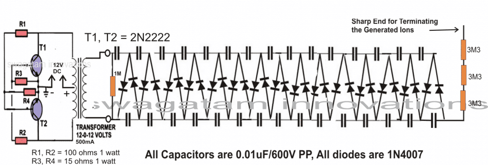


Questions & Answers
Hi
I wanna make a similar ionizer circuit but powered from my arduino which is 3.3V DC and i opened up this USB ionizer i bought online but he seems to use just one transistor and a couple of capacitors, resistors for the initial inverter part
I want to know the circuit for that and also if you could provide a clearer circuit of just the inverter part given above with all wiring connections that would be great
What kind of transformer i should be using and how to connect it. If you could send me a falstad circuit it would be great
The inverter circuit is explained in the following article:
7 Simple Inverter Circuits you can Build at Home
For 3.3 V make sure to use a 3-0-3V / 500 mA or 1 amp step-down transformer.
How else can i connect with you personally for more help
Any email or social networks ur active on
I can be contacted only through this comment platform. You can feel free to ask your questions here.
https://drive.google.com/drive/folders/1re-xqkfHOSbktQSG31koZLyKyw8Ciive?usp=sharing
This is the circuit im trying to recreate!
i want it to be this compact…..i was using this by connecting it to 3.3v of arduino using crocodile pins but now i wanna make an entire custom circuit with this being one part of it
I can see only one transistor, one high voltage capacitor, 2 smd capacitors and resistors used for the inverter part. after the transformer theres is a voltage mutipplier same as u mentioned
Im stuck at the inverter part as to how i should be doing it
That could be a ferrite core based inverter. It is difficult for me to design a ferrite core inverter. I can only provide a large iron core based inverter.
You can easily dismantle or reverse-engineer the prototype, note down the details and then recreate it.
https://tinyurl.com/2gbkfjhx
I have made this seeing your inverter circuit but it doesnt seem to generate a AC output
Can u tell me where i am wrong
Please build the circuit practically which is shown in the above article, it will work without fail.
Hi, I’ve virtually build the inverter shown in this article in Falstad, but there’s not AC output at all!
Hi, build it practically using real components as shown in the article…it will work without fail if you use the correct components and build it correctly.
Hi Swagatam
I want to make if possible to make an analogic frequency duplicator. This circuit, according to my idea, should though a microphone, pick up the sound, convert them (or triple them) and in the next stage reconvert them in analogic order to listen to them again.
Hi Giuseppe, I am not sure if that would be possible, if you think that would be possible there’s no harm in giving it a try!
Hi Swagatam,
is ion generator possible with IR2153 supplied by 220V AC? if yes then give me circuit idea. i have Ozone circuit with it. I want to convert it in ion generator. is it possible?
Hi Nrupesh, if you are using 220V AC as the input, then IR2153 has no role in it. However if you are referring to a IR2153 based inverter to get the 220V AC output, then it is possible, although other simpler inverters will also work as efficiently.
Please help me for a negative ion generator circuit circuit diagram using 0.1 micro farade PF and 1N 4007 diode, and 1M Ohm resistor for the following parameters: –
Input Voltage: – 12 V DC (Battery)
Output Voltage (negative): -6KV with high discharge negative ion.
The above circuit will exactly work as per your required specifications. you can try 0.1uF/600V also for the capacitors.
Hello. can we use smd ceramic capacitors? if yes, then can we use same values ?
Hello, no ceramic caapcitor will not work…..only PPC types will work as shown in the following article:
https://www.homemade-circuits.com/make-room-air-ionizer-circuit-get/
okay thankyou.
But can we use smd capacitors?
The circuit was tested using PPC capacitor so i am not sure whether other types will work or not! If you are having 0.01uF/400 V SMD capacitors, you can try them
Hello, Mr. Swagatam
Thanks for your post. it helped me understand ionizer.
and, could I question a thing? how high should the voltage be to generate ions enough?
what do you think about -2.5~ -3kV?
Hello Mi Jade, any high voltage that is able to generate a bluish glow (corona) around its high voltage end is capable of generating ions. -2.5 V and -3.5 kv should be enough for this process, however -4kv is the ideal voltage for health negative ions
hi.
great work.
i have completed this circuit but i want to use it in electrostatic grass applicator.
to do so, another wire is needed at the out put of this circuit.
where should i put that wire in this schematic?
looking forward for your answer.
Glad you could compete it successfully! Which other wire are you referring to? The high voltage wire is taken from the point where the 3M3 resistors are joined. Please clarify the function or the purpose of this wire, I’ll try to help
Dear Swagatam,
I want a negative ion generator/electron emitter to charge air with negative potential & subsequently charge the water particles. The main thing that I am looking in this unit is it should operate on my 12 volts dry cell type battery & should not involve any electric shocks while operating even if by chance I touch it. Kindly let me know if you have any such product or can make one or suggest where to buy one.
Thanks & best regards,
Santosh
Dear Santosh, when you convert 12V into -4kv then there will be a high voltage condition and a danger of an electric shock, it cannot be avoided.
Many Thanks for the speedy & prompt reply, so whats the solution for this requirement. I want this type of instrument to be handle by me at least for 2 to 3 hrs. a day to work better & I don’t want to get electrocute/burnt the very same time. Seek your expert advice/solution. I am ready to buy the unit.
Thanks & warm regards,
Santosh
You are welcome! The solution is to cover the circuit inside a plastic box and allow only the antenna to protrude out for the required radiation.
Glad to know that we have a solution to avoid the electric shock. Kindly guide where to buy this one. I really want a bundle of safe to handle negative ions/electrons.
Thanks & warm regards,
Santosh
Dear Swagatam, Appreciate your kind & prompt reply. Kindly let me know when I can have this one.
Thanks & warm regards,
Santosh
Thank you Santosh, I will surely let you know!!
Thank you for your interest, however this item will need to built by the user himself. I may try to build it in future and post a video but at this moment it may be difficult. sorry about it
Quick question. If instead of negative charge and negative ions one is interested in creating positive charge. What would be required to accomplish the same?
Basically I need to create a high positive voltage and high positive charge for some experiment and came across this setup which creates just the opposite polarity and wanted to see if I can use the same setup with minor tweaks. Thanks.
You just have to reverse the polarity for all the diodes, that’s all. This would give you approximately +4kv at the pin head.
Appreciate your quick reply Swag.
As my intent was to get high voltage DC potential/ charge, to simplify my build I used an off the shelf high voltage ionizer like the one I have listed below.
The thing I am trying to do is to get the opposite polarity than what this device generates. Do let me know if this is not feasible and if I need to build a circuit from scratch as described in this build with the additional step you suggested.
Thanks again for taking the time to answer my question.
Thanks Jack, modifying the existing unit may not be feasible, so I think you will have to build it from the scratch as given in the relevant articles.
Got it, thanks.
Hello ! Mr. Swagatam
I would like to ark about “Ionizer Generator” . I want to make 18-20kv from 12vdc and low current , How to do the best Ionizer ?
Hello Apisith, I guess 20kv won’t produce healthy ionizing effect, it will produce ozone which is bad for health…
Correction too much is bad for you a little is just fine. Ozone is generated by all ionizers, but its normally at a level thats not noticeable.
Thank for your reply, But I have making a some project about add more Ion into engine only. I have done as your circuit already. It was good condition for engine’s smoke. Then , I want to make a new one to get more ion to test again. Please
For more power you can try increasing the capacitor value to 0.1uF, or 0.33uF and check the results.
Thank you again. Yes, I have done with 0.1uF/630v. x 40 set. But, I can not measure voltage at the end of needle. The current more than 10a. It is too high. I think , It’s should not over 1A .
Ok, Thank you very much I will check it all.
The value of the capacitor will determine the current level, and the voltage rating along with the number of ladder networks will determine the voltage level. With the shown network it will be not more than -4kv, if you double the number of ladders it will become -8kv and so on, but as you go on increasing the ladders the current will go down proportionately, therefore you may have to select the value of the capacitor accordingly for compensating the dropping current.
You an take the help of the following article for more info on this:
https://en.wikipedia.org/wiki/Cockcroft%E2%80%93Walton_generator
10 amp is too high, it means your circuit has problems, you must verify the connections carefully, and rectify the fault
It will produce AC at the output