Generally it is noticed that while charging batteries people hardly pay any special attention toward the procedures. For them charging a battery is simply connecting any DC supply with matching voltage with the battery terminals.
A fast battery charger circuit charges a battery with enhanced speed so that it is charged in less time than the specified period. This is usually done through a step wise current optimization or control.
Objective
The main objective here is to accomplish rapid charging in lead acid batteries without causing any harm to its cells.
Normally, at 25 degrees Celsius atmospheric temperatures , a lead acid battery is supposed to be charged at C/10 rate which would take at least 12 to 14 hours for the battery to get fully charged. Here C = Ah value of the battery
The objective of the concept presented here is to make this process 50% quicker and enable the charging to finish within 8 hours.
Please note that an LM338 based circuit cannot be used to boost the charging rate of a battery, while it is a great voltage regulator IC, enhancing the charging rate requires a special step wise changeover in current which cannot be done using an LM338 IC alone.
The Circuit Concept
When we talk about how to charge a battery quickly we obviously are interested to implement the same with lead acid batteries, since these are the ones which are used extensively for almost all general applications.
The bottom line with lead acid batteries is that these cannot be forced to charge rapidly unless the charger design incorporates an "intelligent" automatic circuitry.
With a Li-ion battery obviously this becomes quite easy by applying the full dose of the specified high current to it and then cutting off as soon as it reaches the full charge level.
However, the above operations could mean fatal if done to a lead acid battery since LA batteries are not designed to accept charge at high current levels continuously.
Therefore in order to pressure current at a rapid pace these batteries need to be charged at a stepped level, wherein the discharged battery is initially applied with a high C1 rate, gradually reduced to C/10 and finally a trickle charge level as the battery approaches a full charge across its terminals. The course could include a minimum of 3 to 4 steps for ensuring maximum "comfort" and safety to battery life.
How to Correctly Charge a Lead Acid Battery
I have seen motor garage mechanics charge all types of batteries with the same power supply source irrespective of the AH rating associated with the particular batteries.
That's gravely wrong! That's like giving the batteries a slow "death". Lead Acid batteries to a very extent are rugged and are capable of taking on the crude charging methods, however it's always recommended to charge even the LA batteries with a lot care. This "care" will not only increase the longevity but will also enhance the efficiency of the unit.
Ideally all batteries should be charged in a step wise manner, meaning the current should be reduced in steps as the voltage nears the "full charge" value.
For a typical Lead Acid battery or an SMF/VRL battery the above approach can be considered very healthy and a reliable method. In this post we are discussing one such automatic step battery charger circuit which can be effectively used for charging most of the rechargeable types of batteries.
Audio/Video Representation
Solid State 3 Step fast Battery Charger Circuit using Only Transistors
The followng diagram shows how to create a simplest, solid state 3 step battery charger circuit using only tramsistors with 3 step current regulation for rapid battery charging.
With this process, a lead acid battery can be fully charged by at least 40 % earlier than the normal charging method.
The design is compact since it avoids the use of relays.
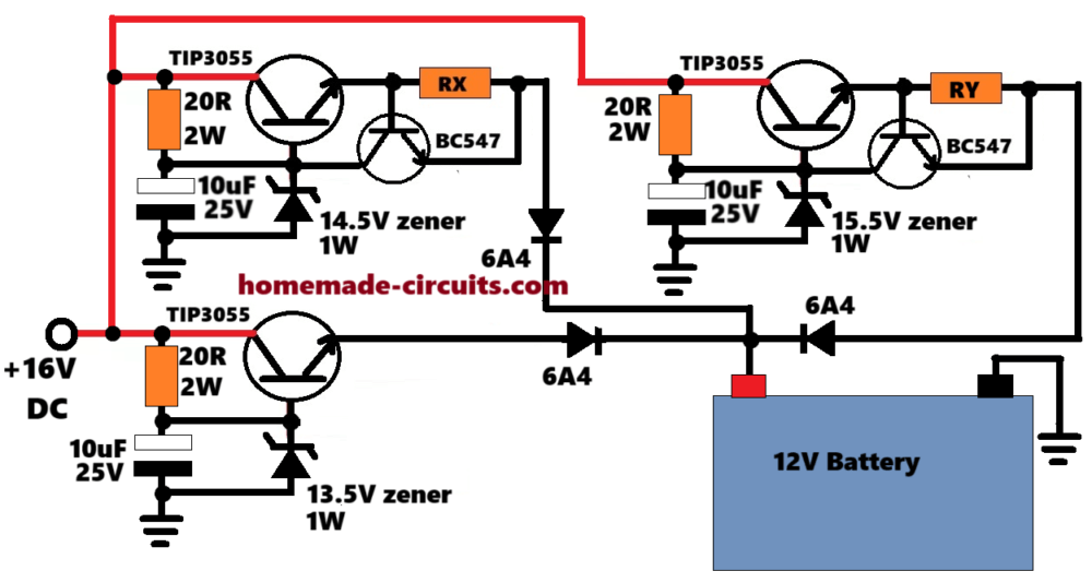
How it Works
Let's consider a12V battery, fully discharged at around 10V.
In this situation, all the 3 transistor stages become conductive and supplly the respective amounts of regulated voltages and current to the battery.
But the lower transistor regulator stage takes precedence over the other two, because it has no current regulation, and thus it supplies a high initial current to the battery.
In this situation, the battery enter the 1st step and starts charging rapidly with a maximum current supply from the bottom TIP3055 voltage regulator, but only until the battery reaches up to 12.3V. At this level, the bottom TIP3055 regulator becomes inactive, because according to its base zener value, its output to the battery positive can be only a maximum of 12.3V, so when the battery charges up to this level, the lower TIP3055 stage stops conducting and is automatically disabled.
Now let's consider, the upper TIP3055 regulator stage with the RX resistor is configured to supply higher current than the TIP3055 with the RY resistor.
Now, at this point, the transistor regulator stage having the RX resistor takes precedence over the RY resistor stage, since it is supposed to have higher current output than the RY stage.
So now the battery enters the second phase or 2nd step of the charging process and the battery continues to charge at a relatively fast pace. But when its terminal voltage reaches at around 13.3V, the RX transistor regulator likewise gets disabled, because according to the top left TIP3055 base zener diode value, its output can supply only up to a maximum of 13.3V to the battery, and at this level the 2nd step charging ends by disabling the top left TIP3055 regulator stage.
Now finally, the 3rd step get automatically reinforced, and top right side TIP3055 regulator stage takes the procedure ahead and continues with the last 3rd step charging process until the battery terminal voltage gradually reaches up to 14.3V, where the charging completely stops, and the battery continues to remains topped up with the attached trickle charging from the top right regulator stage.
In this way the battery completes its 3 step charging procedure silently and efficiently, at a relatively fast rate.
Fast, 3 Step Charger Circuit BJTs and Relays
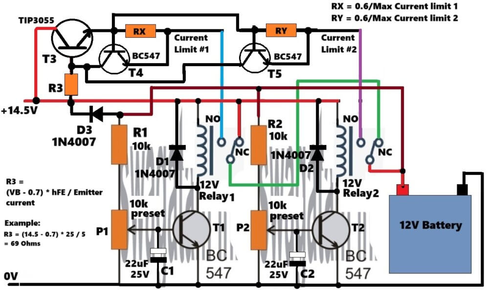
The above circuit diagram shows a simplest 2 transistor, 3 step battery charger circuit using a couple of transistor relay drivers and a TIP3055 stage for the current control.
How the Circuit Works
The working of the circuit is rather simple. Considering a 12V battery, initially, at step 1, the battery charges at relatively high current through the N/C contacts of the two relays using the direct input supply of 14.5V volts.
Then, as soon as the battery voltage reaches above 12.5V, step 2 is initiated and the T1 conducts activating the relay 1, which causes its contacts to move to its N/O point, which allows the battery to receive a slightly reduced amount of current through the RX current sensor setting of the TIP3055 current limiting stage #1.
Now as the battery keeps charging, its terminal voltage keeps rising, and at around 13.5V, step 3 is triggered and the T2 transistor kicks in, activating relay 2. Now the relay 2 contacts move to its N/O position, enabling the battery to get a further reduced current (trickle charge) through the RY current sensor setting of the TIP3055 current limiting stage #2.
How to Set up the Presets
To begin with, do not connect any battery.
Adjust the P1 and P2 presets to keep there wiper arms fully towards the ground.
Make sure to temporarily short circuit the D3 diode with the positive supply.
Keep the current limiter stage disconnected from the relay circuit.
Next, connect a variable DC power supply at the 14.5V input side, and adjust its output to around 12.5V.
Now adjust the P1 until relay 1 just clicks in.
Next, increase the DC supply to around 13.5V, and now adjust P2,until the relay 2 just switches ON.
The P1, P2 setting up procedure is now complete.
Now, remove the D3 shorting, and restore the connections back to exactly as given in the diagram.
Also do not forget to connect the current limier stage with the relay stage, as given in the diagram.
That's it, your 3 step battery charger circuit is all set, and ready to be used with a real discharged battery for a rapid 3 step charging.
Calculating the RX, RY Current Sensing Resistors
Now, its time to adjust the RX, and RY resistors appropriately for the intended stepped current reduction.
Let's say, the initial high current charging was around 5 Amp current, then at the 1st step this needs to be reduced by 40% to around 3 Amps. To enable this we can set the RX value through the following calculations:
RX = 0.6 / 3 = 0.2 Ohms
Power = 0.6 * 3 = 1.8 watts or simply 2 watt resistor will work for RX.
Now, similarly, let's say the RY resistor stage needs to be adjusted for delivering 0.5 Amp current, then:
RY = 0.6 / 0.5 = 1.2 Ohms
Power = 0.6 * 0.5 = 3 watts
3 Step Battery Charger Circuit using op-amps and LM338 IC
Referring to the circuit diagram below, two 741 ICs are configured as comparaters. The presets at pin#2 of each stage is adjusted such that the output goes high after specific voltage levels are identified, or in other words the outputs of the respective ICs are made to go high in sequence after predetermined charge levels are accomplished discretely over the connected battery.
The IC associated with RL1 is the one which conducts first, after say the battery voltage reaches around 13.5V, until this point the battery is charged with the maximum specified current (determined by the value of R1).
Once the charge reaches the above value, RL#1 operates, disconnect R1 and connects R2 in line with the circuit.
R2 is selected higher than R1 and is appropriately calculated to provide a reduced charging current to the battery.
Once the battery terminals reaches the maximum specified charging voltage say at 14.3V, Opamp supporting RL#2 triggers the relay.
RL#2 instantly connects R3 in series with R2 bringing down the current to a trickle charge level.
Resistors R1, R2, and R3 along with the transistor and the IC LM338 forms a current regulator stage, where the value of the resistors determines the maximum allowable current limit to the battery, or the output of the IC LM338.
At this point the battery may be left unattended for many hours, yet the charge level remains perfectly safe, intact and in a topped up condition.
The above 3 step charging process ensures a very efficient way of charging resulting in almost a 98% charge accumulation with the connected battery.
The circuit has been designed by "Swagatam"
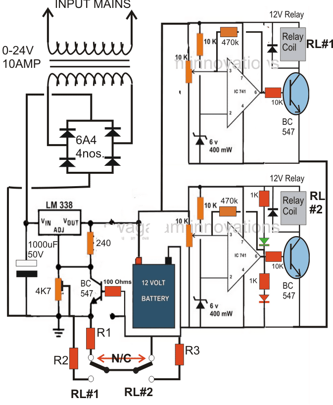
- R1 = 0.6/ half battery AH
- R2 = 0.6/one fifth of battery AH
- R3 = 0.6/one 50th of battery AH.
A closer inspection of the above diagram reveals that during the period when the relay contacts are about to release or move from the N/C position might cause a momentary diconnection of the ground to the circuit which in turn migh result in a ringing effect on the relay operation.
The remedy is to connect the ground of the circuit directly with the bridge rectifier ground and keep the ground from the R1/R2/R3 resistors attached solely with the battery negative. The corrected diagram may be witnessed below:
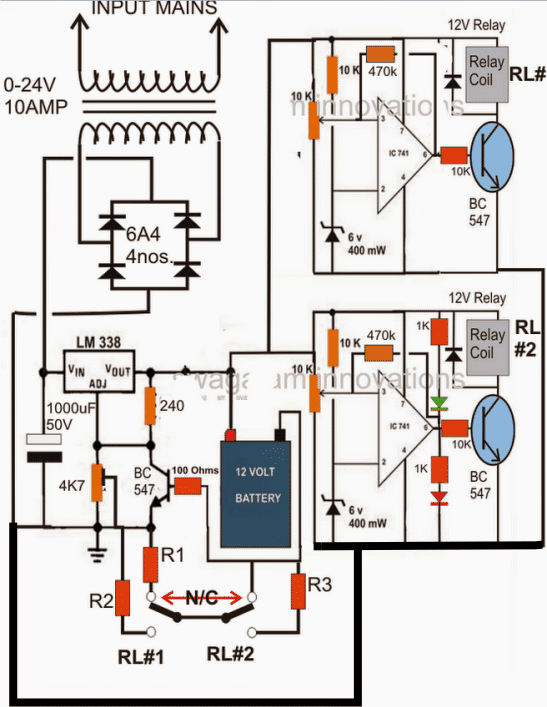
How to Set up the Circuit
Remember if you are using 741 IC then you must remove the red LED from the lower opamp and connect it in series with the base of the transistor to prevent permanent triggering of the transistor due to IC leakage current.
Do the same with the upper transistor base also, connect another LED there.
However if you use an LM358 IC then you may not have to this modification and use the design exactly as given.
Now I have explained how to set it up:
Initially keep the 470K feedback resistors disconnected.
Keep the slider of the presets towards ground line.
Now let's say we want the first relay RL#1 to operate at 13.5V, therefore adjust the LM338 pot to get 13.5V across the circuit supply line. Next, adjust the upper preset slowly until the relay just toggles ON.
Similarly, suppose we want the next transition to happen at 14.3V, ...increase the voltage to 14.3V by carefully adjusting the LM338 pot.
Then tweak the lower 10K preset such that RL#2 just clicks ON.
Done! your set up procedure is complete. Seal of the presets with some kind of glue to keep them fixed in the set positions.
Now you can attach a discharged battery to see the actions happening automatically as the battery charges with a 3 step mode.
The 470K feedback resistor can be actually eliminated and removed, instead you can connect a large value capacitor in the order of 1000uF/25V across the relay coils to restrict threshold chattering of the relay contacts.
4 Step Fast Battery Charger Working
For implementing a 4 step fast charger circuit, here we employ the versatile LM324 for sensing the different voltage levels.
The 4 steps include:
1) High Current Bulk Charging
2) Moderate Current Bulk Charging
3) Absorption Charging
4) Float Charging
The following diagram shows how the IC LM324 may be wired up as a 4 step battery voltage monitor and cut off circuit.
Circuit Diagram
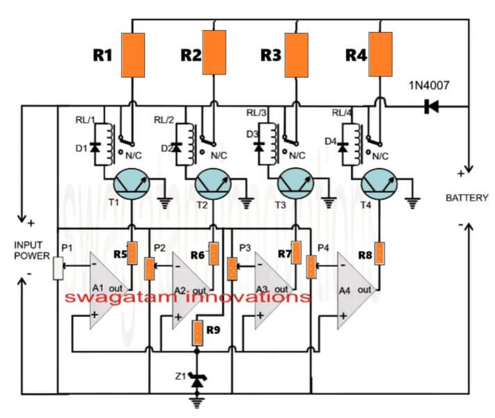
NOTE: Battery must be connected first before switching ON the input, to ensure that the circuit works correctly.
The IC LM324 is quad opamp IC whose all the four opamps are used for the intended sequential switching of the output current levels.
The proceedings are very easy to understand. opamps A1 to A2 are optimized for switching at different voltage levels during the course of the stepped charging of the connected battery.
All the non-inverting inputs of the opamps are referenced to ground through the zener voltage.
The inverting inputs are tied with the positive supply of the circuit via the corresponding presets.
If we assume the battery to be a 12V battery having a discharge level of 11V, P1 may be set such that the relay just disconnects when the battery voltage reaches 12V, P2 may be adjusted to release the relay at 12.5V, P3 may be done for te same at 13.5V and finally P4 could be set for responding at the battery full charge level of 14.3V.
R1----R4 values will be different and optimized to provide the battery with the required amount of current during the various charging voltage levels.
The value could be fixed such that each inductor allows a current passage rate that may be 1/10th of the battery Ah.
It may be determined by using ohms law:
R = I/V
How the circuit responds when switched ON
After connecting the discharged battery across the shown terminals when power is switched ON:
All the opamps inverting inputs experience a correspondingly lower voltage levels than the reference level of the zener voltage.
This prompts all the outputs of the opamps to become high and activates the relays RL/1 to RL/4.
In the above situation the full supply voltage from the input is bypassed to the battery via the N/O contacts of RL1.
The discharged battery now starts charging at a relatively extreme high current rate and rapidly charges upto a level above the discharged level until the set voltage at P1 exceeds the zener reference.
The above forces A1 to switch OFF T1/RL1.
The battery is now inhibited from getting the full supply current but keeps charging with the parallel resistances created by R1, R2, R3, R4 via the corresponding relay contacts.
This makes sure that the battery is charged at the next higher current level determined by the the three parallel inductor net value (resistances).
As the battery charges further, A2 shuts down at the next predetermined voltage level, switching OFF R2 and rendering R3, R4 only with the intended charging current to the battery. This makes sure that the amp level is correspondingly reduced for the battery.
Following the procedures as the battery charges to the next calculated higher level, A3 switches OFF allowing only R4 to maintain the required optimal current level for the battery, until it gets fully charged.
When this happens, A4 finally switches OFF making sure that the battery is now gets completely switched off after attaining the required full charge at the specified fast rate.
The above method of 4 step battery charging ensures a rapid charging without harming the battery internal configuration and makes sure the charge reaches at least at 95%.
R1, R2, R3, R4 may be replaced with equivalent wire wound resistors, however it would mean some heat dissipation from them compared the inductor counterparts.
Normally a lead acid battery would need to be charged for about 10 to 14 hours for allowing at least 90% of charge accumulation. With the above rapid battery charger circuit the same could be done within 5 hours of time, that's 50% quicker.
Parts List
- R1---R4 = As per the below given calculations.
- R5----R9 = 10k 1/4 watt 5% CFR
- P1---P4 = 10k presets
- T1---T4 = BC547
- RL/1---RL/4 = SPDT 12V relays 10amp contact rating
- D1---D4 = 1N4007
- Z1 = 6V, 1/2 watt zener diode
- A1---A4 = LM324 IC
How to Set up
To setup, first keep all the wiper arm of all the presets to ground.
Then connect a variable power supply to the INPUT side of the circuit, so that all the relays turn ON together.
Then adjust the voltage to 12.5V and slowly adjust P1 such that the relay RL/1 just turns OFF.
Next, increase the voltage to 13V and repeat the process for P2, RL/2.
Next, increase the voltage to 13.5V and repeat the process for P3, RL/3.
Next, increase the voltage to 14V and repeat the process for P4, RL/4.
PCB design
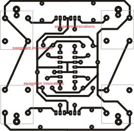
This the original size PCB layout, from the track side, the high watt resistors are not included in the PCB design.
Solving the R1, R2, R3, R4 Resistor Value Problem:
Let's assume we want the relay to switch and deliver current to a 12V 15 Ah battery in the following sequence and conditions:
| Battery Voltage | Active Relays | Active Resistors | Individual Currents | Total Current |
|---|---|---|---|---|
| 11V → 12V | R1, R2, R3, R4 | All 4 ON | 3A + 1A + 0.7A + 0.3A | 5.0A |
| 12V → 13V | R2, R3, R4 | R1 OFF | 1A + 0.7A + 0.3A | 2.0A |
| 13V → 14V | R3, R4 | R1, R2 OFF | 0.7A + 0.3A | 1.0A |
| 14V → 14.3V | R4 | R1, R2, R3 OFF | 0.3A | 0.3A |
| >14.3V | All OFF | Charging stopped | 0 | 0A |
Resistor Values (Calculated at cutoff voltages):
| Resistor | Current | Cut-off Voltage | Vin - Vbat | Resistor Value |
|---|---|---|---|---|
| R1 | 3A | 12V | 2.3V | 2.3 / 3 = 0.77Ω |
| R2 | 1A | 13V | 1.3V | 1.3 / 1 = 1.3Ω |
| R3 | 0.7A | 14V | 0.3V | 0.3 / 0.7 ≈ 0.43Ω |
| R4 | 0.3A | 14.2V | 0.1V | 0.1 / 0.3 ≈ 0.33Ω |
Power Dissipation Formula:
Power = Current² × Resistance
P = I² × R
Full Power Calculations:
R1
- Current = 3A
- Resistance = 0.77Ω
- Power = 3² × 0.77 = 6.93W, so Use 10W or 15W
R2
- Current = 1A
- Resistance = 1.3Ω
- Power = 1² × 1.3 = 1.3W, so Use 5W
R3
- Current = 0.7A
- Resistance = 0.43Ω
- Power = 0.7² × 0.43 = 0.49 × 0.43 ≈ 0.21W, so Use 2W
R4
- Current = 0.3A
- Resistance = 0.33Ω
- Power = 0.3² × 0.33 = 0.09 × 0.33 = 0.0297W, so Use 1W
Final Resistor Table (with Power Ratings)
| Resistor | Resistance | Current | Power Dissipation | Safe Wattage |
|---|---|---|---|---|
| R1 | 0.77Ω | 3A | 6.93W | 10W or 15W |
| R2 | 1.3Ω | 1A | 1.3W | 5W |
| R3 | 0.43Ω | 0.7A | 0.21W | 2W |
| R4 | 0.33Ω | 0.3A | 0.03W | 1W |
Simplest Single Op amp Fast Charger Design
The following diagram shows how a single op amp can be used to create a decent fast charger circuit for a 12V battery.
A discharged battery will be initially charged at a high current rate using the 13V supply, through the N/C contact of the relay. This will allow the battery to be charged quickly at the 13V mark within a few hours.
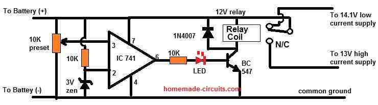
When the battery is charged up to 13V, the relay will changeover to the 14.1 V supply and the battery will start charging through the 14.1 V low current charging supply, until it is fully charged.
How to Set
- Initially keep the 10k preset wiper to the ground level.
- Connect a 13V fixed DC supply with the pin7 and pin4 supply lines of the IC.
- Next, adjust the preset until the relay just clicks ON from N/C to N/O, and the red LED turns ON.
- That's all, this single op amp fast charger circuit is all set now.
Simplest 2-Step Fast Battery Charger Circuit
In this section I will discuss a very simple yet effective battery charger circuit, which will charge your battery at a relatively faster rate than the normal charging methods.
This battery charger circuit can be used for fast charging of all types batteries, however make sure to adjust the current and the voltage of the charger according to the specifications of your battery.
That said, this fast charger circuit employs a step-charging process and therefore is specifically suitable for lead acid batteries and SMF batteries, since these batteries strictly require a step-charging method for implementing the fast charging effect. Li-ion batteries have no such restrictions, and can be quickly charged directly through a relatively high current input, and therefore do not strictly depend on step charging.
Now, let's understand how the circuit is designed to work.
How the Circuit Works
If you do not want to read the explanation below, you can simply watch this video instead:
Referring to the circuit diagram below, we can see that is basically a two step battery charger circuit, which will allow an initial high current charging for a lead acid battery, until the battery voltage has reached around 75% of its full charge level, wherein the circuit will switch the current to a lower level and continue the charging process until the battery attains the full charge level.
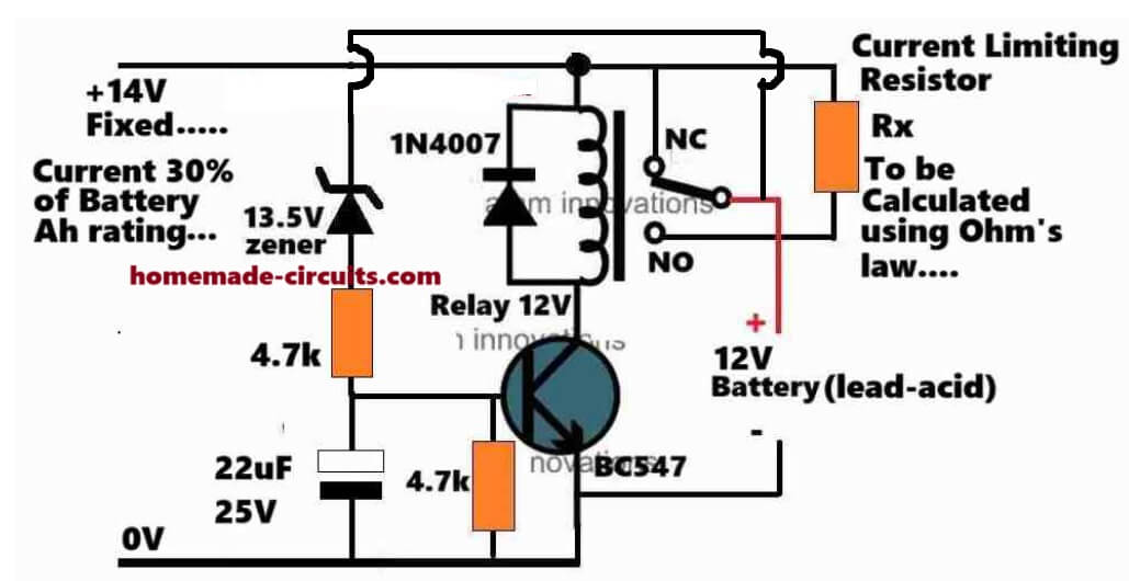
Here, the circuit is configured for fast charging of a 12 volt lead acid battery.
The NPN transistors works like a voltage sensor.
The Zener diode at the base decides at what voltage threshold the transistor needs to switch ON.
Here, the Zener diode is fixed at a 13.5 volt level, which means that the transistor will turn ON when the battery has charged up to the 13.5 volt level.
When the transistor turns ON, the connected relay also turns ON, causing its contacts to shift from its initial N-C contact to its N-O contact.
Initially, while the voltage level of the battery is below the 13.5 volt changeover threshold, the battery is allowed to charge with a relatively high current through the N-C contacts of the relay.
With this initial high current, the battery starts charging at a faster rate and quickly reaches the 13.5 volt level, wherein the transistor switches ON and causes the relay to changeover from its N-C contact to its N-O contacts.
The N-O contacts of the relay can be seen configured with a current limiter stage which consists of a high watt resistor, whose value determines the amount of current that needs to be reduced for the last phase of the charging process.
The battery now continues to charge but with a reduced current until finally it reaches its full charge level.
Please note that here the full charge level for the 12 volt lead acid battery must be restricted to a maximum of 14 volt which is around 0.3 volt lower than its actual maximum full charge level of 14.3 volts.
This reduced full charge level of 14 volt is intentionally chosen to ensure that the battery never reaches its highest 14.3 volt level, which in turn allows the battery to be connected with the reduced supply current indefinitely, without the need of an automatic cut off mechanism.
For a 12 volt lead acid battery, the initial high current charging may be done by using a maximum current which could be around 30% of its A-h rating.
For the current limiting, the above current may be reduced to around 7% of the battery A-h rating.
Calculating the Current Limiting Resistor Rx
The current limiting resistor must be calculated accordingly, using Ohm's law, as shown below:
Rx = V/I = (14 - 13.5)/Ah * 10%
Remember, the initial charging current which is selected here as 30% of the battery A-h must be thoroughly examined. If you find your battery warming up significantly with a 30% initial charging rate, you must reduce this level until the warming of the battery reduces to an acceptable level.
If you have any further questions regarding the above design please feel free to comment below with your queries.


Questions & Answers
Hi! Sir. I have a 15v 5a transformer. I want to use this circuit for charge 12v 50ah car battery. Can you guide me which components should be replace.
Hi Seok,
you won't have to replace anything, you may proceed with the shown design.
Thank you sir! I will try to build this circuit..
Hai sir, I am a sound engineer working in malayalam film industry, but an electronics enthusiast too.
It seems your project be very much helpfull to me in order to make my own inverter which is rated 300 w. but i have some doubts regarding the circuitry
1) First of all i am asking you that, will there be any problem in using a 300 W 12-0-12 V transformer in the circuit since it produces much current (25 A) than that given in the schematic.
2).' Installing a 60 Ah battery needs the addition of a TIP136 over LM338 '. I found this advice in this blog. So please help me to identify this modification correctly by providing me the schematic. Please help me quickly, becoz i am using three 12 V 20ah lead accid batteries in series…..
3).Is there any other modifications needed for complete safeguarding of the battery??
Reply me as earlier as possible to ma email id
dev.arun999@gmail.com
Hi Arun,
If you are referring to the above circuit you can replace LM338 with LM196 and upgrade the circuit to handle upto 10amps.
Rest will remain as is, but the limiting resistors will need to be calculated and fixed appropriately.
Thank you very much sir for replying fast. I am now gonna take care of it. But a doubt still remains that whether the 60 Ah battery can run that much load ( 300 W ) in the inverter. If it can how much hours of back up will i get ?
And using TIP36 over the LM316 means replacing the regulator ic 7812 of the battery charging circuit with TIP36 given in the link
https://www.homemade-circuits.com/2012/11/high-current-transistor-tip36-datasheet.html
with the regulator ic LM196 ?
And also i want to know whether 0.01 ohm with 5w is sufficient instead of a similar one with 2 W, becoz 5w resistors are only available in our area. Can you please suggest me a site to buy these cheep resistance online ?
Hi Arun,
60 AH will not support 300 watts full load, the discharging rate should not exceed 10amps for a 60AH battery, meaning 10 x 12V = 120watts max.
With LM196, TIP136 will not be required, just replace it with LM338 in the above step charger circuit, it will provide you with all the required protections and cut-offs.
Thank you sir for the advice. but a bit of confusion in it.
I am using three 12 V 20 Ah lead accid batteries ( 12EC25L SEALED ZERO MAINTENANCE RECHARGEABLE BATTERIES ) in series which have been taken from my old electric scooter. As per your suggestion 60 Ah can't drow current beyond 10 A. Then how it is possible for the four 20 Ah batteries in the scooter can run a motor rated above 600 W ?
Thank you sir for the advice. but a bit of confusion in it.
I am using three 12 V 20 Ah lead accid batteries ( 12EC25L SEALED ZERO MAINTENANCE RECHARGEABLE BATTERIES ) in series which have been taken from my old electric scooter. As per your suggestion 60 Ah can't drow current beyond 10 A. Then how it is possible for the four 20 Ah batteries in the scooter can run a motor rated above 600 W ?
Is your scooter an electric bike? even if it's so if you check the current at any instant, it won't be above 6 to 10amps….the ideal rate of charging or discharging any lead acid battery is at 1/10th its AH rating…..you can draw higher currents from it, but that would only mean shorter backups from the battery. discharging current is inversely proportional to backup time
Dear sir,
Are those resistors marked as R1 to R3 are necessary in the circuit ? What are their real functions in this circuit ?
The 0.01 ohm resistors are not at all available in our area. Can you please suggest me a website from which i can buy that in smalk quantity ?
WHAT TYPE OF 0.01 OHM RESISTORS I HAVE TO BUY ?
I am asking this because i have seen different types of this resistance in internet such as wirewound, thick film, current sense resistor, surface mount type etc. Which should i prefer most. Please help me
Dear Devraj,
R1, R2, R3 determine and confirm the 3 step charging process, without them the circuit will lose its purpose.
You can put 10nos 1 ohm 1/4 watt resistors in parallel for getting the 0.01 ohm value, by the way R1, R2, R3 will need to be calculated as per the battery being used….did you calculate them as per your battery specs, everything's comprehensively explained in the article, pls read it carefully.
But sir, one doubt whether power will get added on paralling those resistors. I mean whether i will get 2 or more wattage rate for the entire resistor bunk by placing them parallel. Anyway that is very crazy to have such a connection. Anyway i am going to order for 0.01 ohm 2W current sensing resistors. Will that enough ?
Sir a small request is there, please carry on reading…….
Sir i am very much tired of searching for those low value resistors ( of the order of 0.01 ohm ) in the internet. I need some few of them, but all of the websites that i searched want me to buy an atleast quantity which is predetermined by them and at the highest rates i have to pay. If anyone is gonna make this circuit, they will probably meet this dilemma for higher values of battery Ah.
SIR as per your design, the more higher the battery Ah, lower will be the resistance values ( R1, R2 and R3 ). So could you please suggest us a more better circuit utilizing almost all features of this one, but having no such low valued components included also having the feature of charging higer Ah batteries too.
( As per your previous reply to ma comment i will not get 0.01 ohm resistor with ten 1 ohm resistors. Please not it……. I will have to take hundred instead of ten. It will not be feasible sir )
I HOPE A QUICK REPLY SIR………
I just forgot to tell you that LM338 wil not hold more than 5 amps, meaning more ta 50 AH batteries can't be charged with is circuit.
A transistorized current controller can be replaced for LM338, but even it will require the same low value resistors.
One solution is to use resistor divider network which will allow us to use higher value resistors.
I'll try to update the article soon.
Good evening, sir, and thanks a lot for this very educative blog.
I would like to build a charger for a 12V-66AH Automotive battery based on the above schematic.
I have done the following modifications:
1. Replaced the LM338 with an LM196 Adjustable Voltage Regulator
2. Replaced the 4no. Rectifier Diodes 6A4 with a single Bridge Rectifier KBU1000
3. Installed a 10A05 Rectifier Diode across each of the Relay Coils
Please advise me if there is anything else I may have overlooked.
I thank you in advance.
Thanks Ronald,
Everything's rightly done, just be sure you use the correct calculated value resistors for R1, R2, R3.
Thank you very much much for your quick reply. I will now embark on building the charger.
Your help is greatly appreciated
By the way, am I right to assume that the same formulas above are to be used in computing the R1, R2 and R3 Resistor values, i.e.
R1 = 0.6/ half battery AH
R2 = 0.6/one fifth of battery AH
R3 = 0.6/one 50th of battery AH
Again I thank you.
You are welcome.
Yes, The formulas will be exactly as shown in the article.
Sir can i reduce a 25 A dc current to 5 A or less using LM196 IC????
If yes how can it be done ?????'
yes you can do it.
…please refer to this post, it's explained there:
https://www.homemade-circuits.com/2013/06/universal-high-watt-led-current-limiter.html
Can you please suggest me a NTC THERMISTOR having resistance of atmost 500 ohm and power dissipation of 40 J SIR????'
Sir how can i depict the Joule rate in terms of wattage?
I have found many specified with only Wattage not with Joules.
How much wattage curresponds to a 40J rate. Is it 40 W or 40 mW????
Hi Nazriya,
You will have to check the datasheet of an NTC thermistor manufacturer for getting the required value, I do not have the info right now.
Here's the formula for converting J to W
The power P in watts (W) is equal to the energy E in joules (J), divided by the time period t in seconds (s):
P(W) = E(J) / t(s)
Hi, im interested in doing a simple project of controlling home electrical system fan, tube light through remote control. can you pls help me by your simple circuit diagram so that it is very helpful and easy for me to do.
Hi, You can try and use the design which is shown in the following article
https://www.homemade-circuits.com/2013/07/simple-100-meter-rf-module-remote.html
It will allow you to control 4 different appliances separately
Hey Swagatam,please tell me how to make this 3 stage battery charger using microcontroller instead of using those 2 comparators?
Hi Charu, I do not have the codes presently, if I happen to get it will post it for you.
Hi sir swatagam,
is the circuit can be modify to charge a 12vdc 100ah deep cycle battery?
if ok, please tell what are the modification should i do.
thanks in advance.
Hi Joevil, the above circuit is not applicable for above 50AH battery.
you can try the following one:
https://www.homemade-circuits.com/2011/12/high-current-10-to-20-amp-automatic.html
Hi Swagatam,
I have assemble the above circuit, i am using 12v 7Ah battery. As per the above calculation for R1, R2 & R3 i am getting the (R1 value 0.17 Ohm). (R2 value 0.34 Ohm) & (R3 value 0.68 Ohm) please correct me if i am wrong in the calculation.
Thanks & Regards
Anandan
Hi Anandan, as per the given suggestions in the article, R1 is correct, R2 should be around 0.42 ohms, and R3 = 4.7k
Hi Swagatam,
Thanks for the reply.
I have 0.47 ohms resistor is it ok in place of 0.42 ohm for R2?
I will be using solar panel instead of transformer which is rated 17volt 25watts, as i see in the above diagram trafo spec is 0-24v will the solar panel rated 17volt will work?
Thanks & Regards
Anandan
Hi Anandan,
yes 0.47 will do, the values are not critical because the recommended charging phases are not critical either.
17V will be enough to operate the proposed system…
Hi Swagatam,
Thanks for reply.
Currently i am using LM338 but i noticed when the battery was fully discharged to 10.5 v
and kept for charging even the LM338 on heat-sink was getting hot.
I see most of the people using LM317 for 7ah battery, will LM317 work for charging the 7AH battery or do u recommend to use LM338 only.
Thanks & Regards,
Anandan
Hi Anandan,
LM338 is rated to handle upto 5amps and LM317 only upto 1.5amps…so if LM338 is getting hot LM317 will be even hotter…moreover LM317 will allow charging at the rate of 1.5amp max, therefore LM338 looks much better than LM317
Hi Swagatam,
Thanks for reply.
I have designed PCB for this circuit and all component are on it i have put a fix resistor in place of 4.7k preset (2.2k & 330ohms in series) i get 14.5 v at LM338 output.
Now i want to align the preset for RL1 & RL2, can u please explain in short how to align?
Thanks & Regards,
Anandan
Hi Anandan,
Initially keep the 470k resistors disconnected, then feed 13.5V to the circuit and adjust the upper 10K preset such that the relay RL1 just actuates at around 13.5V
Next, increase the volts to 14.3V and adjust the lower 10k preset such that the RL2 just activates at this volts.
Now reconnect both the 470Ks, the setting is done.
Do the above without connecting any battery.
Hi Swagatam,
For alignment of the preset for RL1 & RL2 i connect the discharge battery and kept the both the relay in normally connected mode and as the battery reached 13.5v i align the preset so the RL1 get trigger and waited till the batter voltage reach 14v and aligned the preset for RL2 so it get trigger. Battery gt fully charged up to 14.4v 🙂 but after i discharged the battery and started charging back again the RL1 started ringing after the battery reached 13.5v 🙁 please correct me if i did any thing wrong.
Thanks & Regards,
Anandan
Hi Anandan, use the method as described in the previous comment for setting up the circuit and put a 100uF/25V across both the relay coils for eliminating the ringing sound.
Hi Swagatam,
Thanks a lot for reply
I will do the same as you have mention above and let u know the result. 🙂
Thanks & Regards,
Anandan
I want to charge a 12v battery using a car alternator (so 14.4v). Is this circuit worth modifying for that? or should I be looking for some other solution?
nothing will need to modified except the trafo which will have no role in your application…use a 10k pot instead of the shown 4k7 for setting up the LM338 voltage…
Thanks for the response. The datasheet for the LM338 says the dropout voltage is up to 3v, meaning the maximum output is somewhere around 11.4-12v for a 14.4v input, correct?
according it has to be just 0.5V higher than the intended output voltage from the IC.
hi sir, you are doing the wonderful job ,i really appreciate your knowledge and work .i could not understand the use of bc547 located just above the R1 .will this affect the circuit ???
thanks krishna, the indicated BC547 is responsible for interacting with the relay contact changeovers and implementing the subsequent current limiting actions….so in a way it's the heart of the entire design
HI Swagatam,
As per ur suggestion i tried adjusting the circuit but when i increase the voltage to 14.3v and try to adjust the RL2 preset its starts ringing on & off, i have also connected the capacitor on both relay 100uf 25v .
kindly suggest what could be done.
Thanks,
Anandan.
Hi Anandan, that should not happen, check R1, R2, R3 connections and there continuity, or temporarily short the emitter base black dots of the BC547 associated with these resistors and adjust again, if the ringing stops would indicate a wrongly connected R1,R2,R3.