This circuit is capable of providing as high as 25 Amps of current at any specified voltage between 1.25 V to 30V as per the adjustment of the given pot. The current is constant irrespective of the voltage settings. The circuit can be used for charging batteries in range of 50 to 200 AH.
How it Works
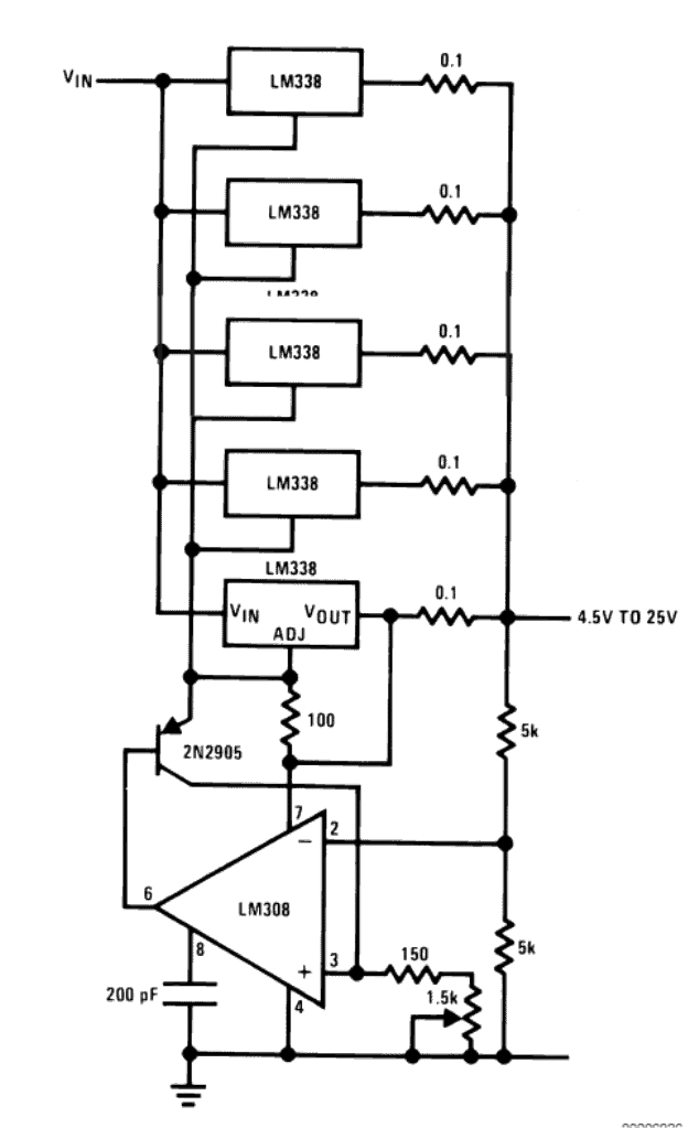
The figure below shows a straightforward design of a simple high current solar battery charger power supply circuit which would generate a constant 25 amps of current from any source which is able to generate currents in excess of 25 amps and at 32 volts maximum.
We know that the IC LM338 is specified with a maximum of 5 amp current, the IC restricts anything above this limit.
By connecting 5 of these ICs in parallel it thus becomes possible to generate a current output of about 25 amps. The great thing about using these ICs is that, these devices are internally protected from thermal runaway situations and short circuit or overload conditions.
It means the present circuit automatically becomes safe from such adverse parameters and thus becomes completely indestructible given the input is not exceeded above 32 volts.
However the ICs cannot be directly connected in parallel, because that would cause a difference in the voltages at the output from each of the ICs which in turn would cause an imbalance between the IC dissipation, this wouldn't be good for the overall functioning of the circuit.
Therefore the additional components in the form of the opamp and the transistor have been included in the circuit which controls and maintains a constant voltage output from all the ICs keeping the situation well under control.


Questions & Answers
Dear swagaam,
I too am trying to make a high current charger, in my instance 25A is good, however I wish to charge 36V battery banks connected in series, would I need different ICs instead of the LM338’s, also I would like to control both voltage and current.
As I wish to limit charging at times I assume I would need to reduce current and keep voltage steady.
Any help, pointers are links to a kit would be great.
Regards
Hi ChrisF,
You can try the second diagram from the following article. The LM338 must be LM338HV which can handle upto 60 V input. You can connect 8 to 10 numbers of these ICs in parallel over a SINGLE COMMON HEATSINK, so that the heat dissipation of the ICs can be shared and all the ICs can conduct uniformly.
https://www.homemade-circuits.com/how-to-build-solar-panel-voltage/
Hi Swatatam,
Many thanks for the suggestion of the LM338HV, it really looks simplistic and easy to build, on an initial search I’m struggling to find the LM338HV, I can find LM317HV’s. Let me tell you a little more about my application.
36V 50A Lithium Iron battery bank x3 connected in series (108VDC) that need to be charged when there is excess production from the sun – I will AC couple, i.e. solar inverters connected to grid.
Charger would then ramp up when we get to an export situation (a bit like the iboost for immersion heaters), charging voltage would need to be controlled to allow keeping the battery from full charge (full charge can take place when balancing is required), voltage to be max 43.5v, Charging current would need to be controlled as charging should only take place when we are exporting and charge current should be more with greater export.
So basically I wish to add an MCU (ESP32) which will talk to the batteries, monitor export/import current, this would provide 2x 0-3.3vdc pins for PWM that will effectively give 0-3.3VDC, one for current control, one for Voltage control.
I assume that the control inputs and ground references would need some form of opto-isolation due to the common MCU unless I keep 1 MCU per 36V charger module.
I would then need either a SMPS or conventional TX / Bridge and Caps for providing the DC from the Grid.
I guess in reality this would be something like a 36V golf cart charger, but with the ability to control it via MCU.
I really hope you can help me with this, you have some good circuits and have excellent feedback, if you think what I’m trying to achieve is not the right approach or just not doable please do tell me.
I do think that many DIY enthusiasts will be interested in something like this as there is something that has been shown on a forum (https://discord.com/channels/429907082951524364/1066099202528129024) however replies are not coming forward.
Regards
Thank you ChrisF,
What you are doing looks OK to me, however, your battery system cannot be charged with the simple circuit which I provided you, it looks much more complex than that.
I can only help with simple chargers without BMS and without MCU, so your requirement looks beyond the level of my expertise.
I wish I could help you but I don’t think I can.
The link which you sent is not opening, it is asking me login or signup.
Dear swagaam,
I have connected two LM338 in parallel as 220 ohm accros output and adjusting pins of each IC then both adjustment with 5k Pot. Now One IC is getting hotter while other is cool on 2 Amp load. I think current is flowing through one IC only. Input is 12v from ATX SMPS. Please help me how to balance current flow through both without using OP-Amp.
Regards
Dear Nisar, yes that’s right, current may be flowing through one of the LM338 ICs causing an imbalance. You can do one thing, mount both the ICs over a common heatsink close to each other, then the problem will be solved.
Thank you brother for your prompt reply. I will do the same as you suggested.
Regards
No problem Nisar, wish you all the best!
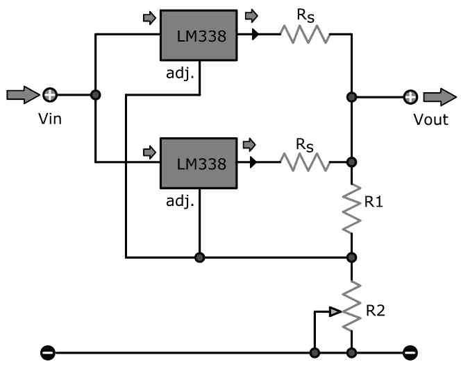
Swagatam , I think I found what you are suggesting at this link, where they place two lm380-s in parrallel with each other……..>
I have to be able to set the voltage to EXACTLY 14.8 for my AGM Battery bank, with no deviation, and it has to be controlled at the 14.8 level otherwise overcharge of Battery bank, means destruction of bank.
Will this do?
Regards
Roberto
You are right Roberto, but for a 12V battery the adjustment must be 14.2V, and not 14.8V…..14.4V is the highest value beyond which the battery may over charge
Swagatam says:
“Roberto, I do understand your problem, that’s why i recommend you to remove the opamp stage and connect all the LM338 in parallel..”
Swagatam, Could you please direct me to a circuit diagram that would show what you mean, as I do not understant how the transistor base will be driven if the op amp is removed.
Thank you so kindly Swagatam, as I have been struggling for a week now, with no success.
Enjoy your weekend Swagatam
Shalom.
Roberto, I am referring to a circuit without an auto cut off, because the LM338 itself will act like an auto cut off when the battery voltage and the LM338 output voltage becomes equal, meaning when the battery reaches full charge level. To ensure that the battery never crosses the full charge level we have to adjust the LM338 output slightly lower than the battery full charge level. Meaning if the battery full charge voltage is 14.3V, then we can adjust the LM338 output to 14.1V.
If you are OK with this concept then please confirm I will provide the diagram to you.
Swagatam
Please have patients with me as I am 67 years old and need to build this damn circuit and get it working to charge my solar battery bank of 360Ah when we don’t have sunlight for a few days.
Thanks
Rob.
Roberto, I do understand your problem, that’s why i recommend you to remove the opamp stage and connect all the LM338 in parallel over a common heatsink.
After this adjust the common pot of the circuit to produce an output voltage that’s slightly lower than the full charge level of the battery.
Once this is done you can connect the output of the circuit with the battery for safely charging the battery to optimal levels.
Swagatam
I have built the circuit but my input voltage = output voltage ! What am I doing wrong?
I used a 471 instead of LM308 and used exactly the same pin connections.
Used BD140 instead of 2N2905
The LM338-s , I mounted on a Heatzink, and they are all isolated completely from the metal of the heatzink and each other.
There is no/non adjustment of the voltage from turning the potentiometer.
All resistors are 0.1ohm
Hi Roberto, I can understand your problem, but it will be difficult for me to troubleshoot your circuit without checking it practically.
Also, this circuit was taken from the datasheet of the IC LM338, it was not designed by me.
That said I would recommend you to completely remove the op amp, and connect all the LM338 in parallel, then adjust the common pot to a level that’s slightly lower than your battery’s full charge level. After this you can connect the output to your battery.
But for the above design you must connect all the LM338 over a common heatsink so that they all can share the heat dissipation uniformly.
This set up can charge your battery optimally without overcharging it.
Hi Swagatham
I am busy looking at your circuit trying to understand everything before I build it. One thing I am not sure of is the supply pin 7 of the opamp that is wired to the regulator adjust pin. Is this intentional and if so, please explain to me what the theory is behind that.
Hi Marius, this circuit is not designed by me, it was taken from the LM338 datasheet. Pin7 of the opamp is intentionally connected to the output of one of the LM338 ICs so that it gets regulated voltage from the LM338. The level of voltage at pin7 is not crucial as it can work satisfactorily with any voltage between 4.5V and 15V, for higher ranges you can replace the LM308 with LM358 or LM321
Thanks for that explanation. It makes sense. I might then put a regulated voltage on pin 7 as I am already making a regulated voltage available for other parts of the application.
You are welcome Marius…
Are there Other ICs substitutes in case, I can not find the actual ICs?
I would like you to send me some
Transistor(s) solar charger circuit designs.Thanks in advance.
You can IC 741, and use a series LED with pin6…..
What is the wattage of the 0.1 ohm resistors?
0.2 x 5 = 1 watt
Hi Swagatham,
this circuit is what i need for a long time, but unfortunately my panels are 36 volts so is it possible to make this circuit for 36volts input?
Hi Cem, 36 V is the maximum working limit for LM338 so I won’t recommend driving the IC at its maximum limits. By the way it is possible to create a good charger using a single MOSFET arrangement.
Please specify your solar panel V and I details and also the battery’s V and Ah details I will try to suggest a suitable design.
You are really a great man Swagatam, thank you very much. I have five sun panels 320watt per, Voc=39v max and Isc=10A. They are in parallel design and 50Amps to drive 24v water heater or some other heating tools for handcrafts such as small oven, plastic melting toll, soldering irons etc. I have bought an 50A mppt controller already but it couldn’t manage and now it is out of order. My aim is to get maximum amps at 24v to heat my needs quickly and also security for the panels. By the way my gel battery pack is 24v at 300AH
No problem Cem, I think a buck converter will be more efficient for your application than a complex MPPT. You can include the following concept with each of your panels and then combine the individual buck outputs to get the intended high power optimized output.
PWM Solar Battery Charger Circuit
THe output can be change to be 24 V by adjusting R8/R9 values appropriately
Alternatively you can also try the following concept:
https://www.homemade-circuits.com/lm317-variable-switch-mode-power-supply/
However you may have to upgrade the Q1 transistor and the coil wire thickness for getting the 10 amp output
Here’s another design perfectly suitable for your application:
https://www.ti.com/lit/ds/symlink/lm5145.pdf?ts=1592229037795&ref_url=https%253A%252F%252Fwww.ti.com%252Fproduct%252FLM5145
Thanx again Swagatam, I will try your suggestions and after now I am a big fan of you. Best wishes.
You are most welcome Cem!
HELLO AGAIN LONG TIME FOLLOWER OF YOUR BLOG I HAVE BUILT MANY OF YOUR CIRCUITS THIS IS MY PROBLEM I HAVE A 12V LITE THAT I LIKE VERY MUCH BUT IT HAS AN INCANDESCENT BULB AND AS YOU KNOW THOSE BULBS ARE A THING OF THE PAST. COULD YOU DESIGN A SOFT START CIRCUIT TO PROLONG THE LIFE OF THE TWO BULBS I HAVE . THANKS SO VERY MUCH
Thanks Bruce,
you can try the following circuit:
Hi
I want to know it will be work on atransformer or a solar panel or both
it will work with all types DC inputs
pls send the 1a , 5a and 10a charger circuit for solar panels. i have tried with so many circuit but i am not getting exact output from that please send detailed circuit for solar charger with charging, battery low and battery full indications
you can try the following circuit:
https://www.homemade-circuits.com/2012/04/how-to-make-solar-battery-charger.html
use LM317 for amp…LM338 for 5 amp and LM396 for 10amp.
use a 18v panel and a 12V battery with the panel…
Hello Sir,
Sometimes the electricity can be unstable at times. But will need stable voltage to charge batteries so is it possible to have constant voltage and at the same time have a desirable constant current range depending on how many batteries I want to charge.
Basically if i have 3 (12v)batteries and I want to charge just one of them, I want to be able to selext the charging current and voltage. Then if I want to charge two batteries connected in series to give 24v then I want to selxt charge current and voltage too.
Kind of like a flexible charger.
I don't mind how many IC I have to buy but is IR doable.
Hello Michael,
yes it's possible, you can follow the instructions as given in the following articles in order to altyer the specs as per your specific needs:
https://www.homemade-circuits.com/2015/07/designing-customized-battery-charger.html
https://www.homemade-circuits.com/2015/07/designing-customized-battery-charger_13.html
Hi Swagatam,
Thanks. Can i use 2-3panels in parallel with this circuit to get 16-24 amp. Or can i add the fourth one too for getting close to 32 amp peak and generally around 20-28 during most day.
Regards
Gopal
Hi Gopal, yes that surely is possible, you may go ahead with it.
What is the power rating of resistors?
0.1ohm @ 5Watts?
the rest of the resistors @ 0.5 Watts?
yes, will do.
Hi Swagatham,
I want to use the above circuit, however the Solar panels have rated voltage as 30.04 and are generally recording about 31-32.5 Volts/8 Amp when placed in Sun, will I be able to use this circuit for charging 150AH batteries.
Gopal
Hi Gopal,
The above circuit will be able to handle upto 25amps, so according to me you can use it for charging a 150AH battery easily with the mentioned solar panel, but 8amps won't be sufficient and make the process very slow