In this post I have explained an LED based intruder position indicator circuit which will indicate the position of the burglar throughout the secured corridor as the person tries to sneak past the area.The idea was requested by Mr. Michael.
Circuit Objectives and Requirements
- Your articles are nice, well done. sir can this, close and open door security circuit be mounted on an iron door?
- Sir can you help me with a security circuit that will have five to ten(5-10)light emitting diode indicating the position of an intruder in a house.
- The circuit will work in such a way that when the intruder is at your gate,the LED will light up and when he or she enters your compound, the second one will light on.
The Design
The requested idea can be actually implemented through a few very basic circuits as described below:
Using an LED/LDR laser beam interruption method.
Using an proximity sensor circuit
Using piezo electric device sensor
Using a PIR based circuit.
Here we will pick the most simple one out of the four options, and utilize the piezo sensor concept for implementing the position intruder indicator circuit and detecting an intruder who may crossing the prohibited section of the premise.
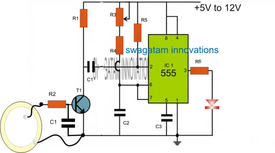
As shown in the figure below, the proposed intruder position indicator security circuit can be built by positioning many such modules across all those areas which need to be monitored.
How it Works
The circuit basically consists of a monostable multibrator circuit using the IC 555, which is activated when T1 is activated through the attached piezo buzzer element.
We have already learned from one of our previous post regarding how a piezo could be used for generating electricity, here the same concept is enforced for triggering the transistor in response to a physical strike or vibration on the piezo.
For implementing the intruder position indication, one such unit could be positioned across each of the selected strategic locations, with the piezo element hidden inside a carpet or a door mat.
Whenever an intruder attempts to cross the secured zone, the person steps on the carpet or the door mat where the piezo is installed, and in the process triggers the circuit into action, illuminating the LED.
The circuit module could be installed somewhere near to the piezo, and the LED terminated and fitted at the location where the LED indication is required to be visualized.
The values of R3, R4, and C2 determine for how long the LED remains switched ON and then switched OFF once the piezo is triggered, and these could be appropriately adjusted for acquiring any desired length of illumination period.
Parts list
- R1, R4, R5 = 100K
- R2, R6 = 1K
- R3 = 1M pot
- C1 at T1 base = 1uF polar or nonpolar
- C1 at T1 collector = 4.7uF/25V
- C2 = 100uF/25V
- C3 = 10nF



Questions & Answers
all catched loud and clear, well as a begginer I do not understand fully why C1 is doing there as I undertood so far, capacitors block dc current and allows ac current with sume impedance, but here the pin 2 has to be high always, and as soon as it gets 0 low or ground the 555 starts timing, and with this mister c1 The capacitor is always gonna see ground as c1 is always gonna block the dc current, so there are lot of confussion only with the capacitor thanks…..
The pin#2 C1 will see the ground only when the T1 conducts, but because capacitors stop conducting as soon as they charge up, here too C1 conducts only momentarily until it's full charged via T1.
in short C1 ensures that regardless of the T1 switch ON time, pin#2 is grounded only for a fraction of a second for initiating its triggering.
oh I see, so C1 allows that as soon as feet stops stepping on Piezoelectric, the 555 and led will turn off? so it is for 555 not to see ground all the time but a little time and then open circuit?
No, C1 makes sure that the IC restricts the pin2 grounding only for a fraction of a second regardless of how many times the piezo is stepped during that instant…
yes pin#2 always sees positive through the 100K resistor until the time when T1 is conducting
Thanks, I have learned alot with your circuits, one last question, is it possible to turn a buzzer just for a second using a capacitor in series, I want a basic pir sensor to turn a transistor and relay on but aditionally I will love that a tiny buzzing sound and done, but I guess the capacitor will affect the circuit then I get complicated to do it
Yes it's possible, jut connect a piezo buzzer parallel to the load or the relay coil with a series capacitor (10uF)….and connect a 1M resistor parallel with this capacitor to ensure proper discharging each time the unit is switched OFF.
Hello Swagatam, I have a question about a circuit that I am making. It's is a small analogue camp alarm and has great safety against false alarm etc. I having a problem as I can not make it work. Would you please have a look at the circuit diagram, maybe you'd be able to to help. How can I send you the diagram?
Hello Cyrus, if the ICs are familiar then may be I would be able to help you….you can send it to my email ID, see my contact page to find it.
Hi, could you suggest a circuit based on break wire ( thin long copper wire). I need it for protection of camp sites against intruders or bears. It should have arming delay to allow for set up of device and be false alarm proof. Thank you
you can try the following concept:
https://www.homemade-circuits.com/2011/12/how-to-build-and-install-simple-car.html
here the alarm will sound only for a few seconds and then stop, which can be increased by increasing the value of C2/R2/R3
Sir,
Would you know the equivalent of Ss8050?
Thanks
you can try 2N2222
Good day sir,
May I know the parts number of T1?
Thank you
Rav, you can use BC547 for it.
I was of the very different opinion when I read the title of this project… my impression was that the proximity sensors like PIR, Doppler Magnetic sensors, Ultra Sound is is used here .. to my surprise this very KISS project and inadequate IMO for perimeter breach & proximity sensing … I would like to implement one that would sense the intruder movement using sensors .. even the ckt. above to relay the signal .. RF 433Mhz, Bluetooth etc, .. with no false positives.. to a central hub .. wirelessly / wired … weather and tamper proof… which in turn may notify me on my smartphone by SMS or to Twitter & if there is Camera involved with uploading of pictures… obviously all of this may involve ESP8266, Arduino, Raspberry… speaking of camera must be AI enabled to prevent false motion sense … am I asking too much? The above ckt may be daisy chained along the possible entry points for easy maint., zoning, single UPS psu,
Good day Swagatam
Thank you for your innovative circuits and ideas.
I am busy building the Piezo circuit and am confused with the pinout connections as marked on the schematic, as they seem different to the pinouts on an IC555, and I do not want to destroy the chip.
Do I connect them to the figures as marked on the schematic or as positioned on the chip?
My second query is as follows:
Am I able to replace the Piezo mat with a 3,3 volt contact sensor, or will the circuit have to change?
I hope you can understand my questions and I look forward in anticipation to your reply.
Regards, John
Good day John,
you can compare the 555 pins shown in the diagram with the following image, and do the connections accordingly:
Can you please elaborate on the functioning details of the 3.3 V contact sensor, tried to find it online but could not get any info…