The door security alarm circuit discussed in this article alerts the user whenever the door fitted with the circuit is opened or closed or even moved from its original locked position.
Using a Reed Relay and Magnet for the Triggering
The idea utilizes the very basic reed relay and magnet concept across the door and the door frame. The magnet is attached with the door edge, while the reed relay and its associated circuit is fixed on the door frame exactly adjacent to the door magnet, such that both are almost touching each other and separated only by the door and frame clearance.
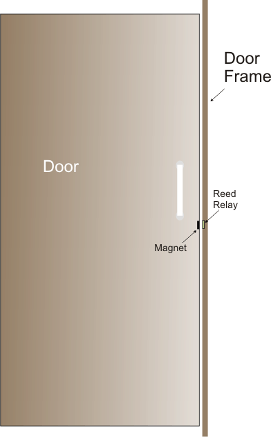
This implies that whenever the door is moved or opened the magnetic influence on the reed relay is inhibited, which causes the associated circuitry to trigger the alarm.
The reed relay is connected with a delay OFF timer circuit, which makes sure that as soon as the door is opened or closed even for a fraction of a second causes the alarm to activate and sound for at least a few 10s of seconds, after which it automatically resets, until the door is moved yet again.
Parts List
- Resistors 1/4 watt 5%
- 10K = 1
- 22K = 1
- Capacitor Electrolytic
- 1000uF/25V = 1
- Transistors
- BC557 = 1
- 2N2222 = 1
- Alarm = Any piezo alarm siren unit
How it Works
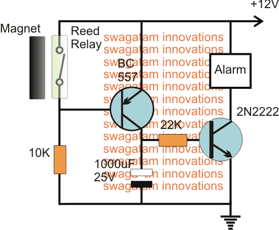
The arrangement can be seen in the above diagram which shows how the door open close alarm circuit needs to be configured which appears pretty straightforward.
As long as the door remains in the closed position, the magnet enables the reed in the switched ON or "closed" position, which in turn keeps the PNP BC557 switched OFF.
With BC557 switched OFF, the 2N2222 is also unable to conduct, and thus the connected alarm module continues to be silent.
However in a situation where the door is moved or opened by an intruder, causes the the magnet to shift from its original position, which instantly opens and releases the reed internal contacts.
The above action now enables the BC557 to conduct, subsequently enabling the 2N2222 also to trigger and ultimately switch ON the connected alarm unit.
The intruder realizes this and tries to close the door in an attempt to shut off the alarm, however due to the presence of the 1000uF capacitor, and the 22K resistor at the base of the 2N2222, the transistor continues to conducts ensuring that the alarm is not switched off even though the door is restored at its initial position....thus the alarm stays latched ON and continues to raise the alarm forcing the intruder to surrender himself, until the 1000uF capacitor has discharged completely.
This little inexpensive yet highly efficient door opening alarm circuit can be used for securing any desired entrance from a possible intrusion without the need of a constant monitoring or without a guard in position.
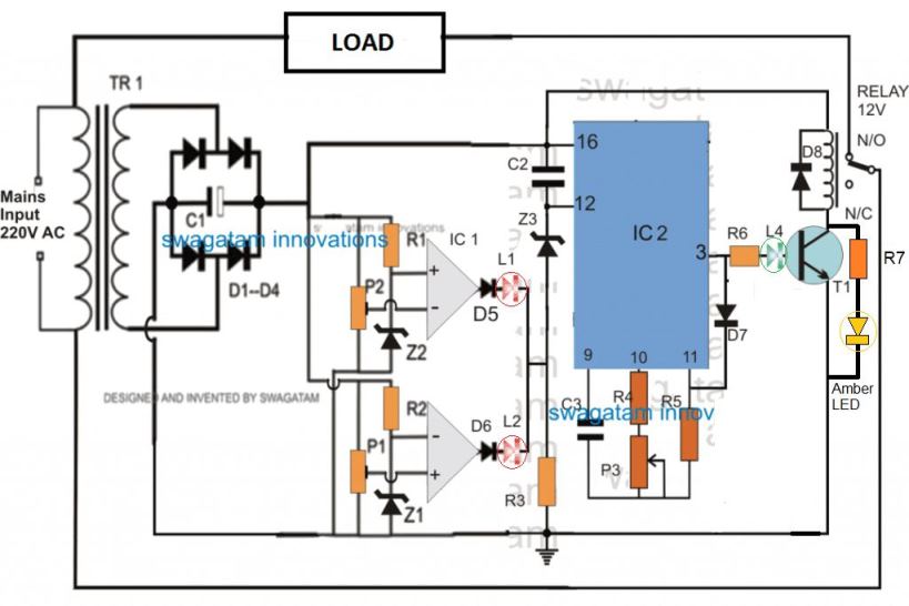
Using IC 4093
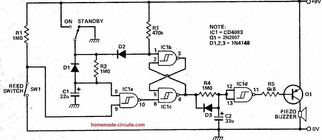
This door alarm circuit is constructed around an affordable CMOS 4093 integrated circuit (IC) and offers a battery-operated burglar alarm for doors. The system incorporates both entry and exit delay functionalities.
The compact design of the unit makes it suitable to be enclosed in a small plastic enclosure, which can then be affixed to the inner side of the door requiring protection.
A small bar magnet is placed on the door frame, positioned within the range of the magnetic reed switch located in the alarm enclosure.
This setup ensures that the system functions as a self-contained unit, eliminating the need for any installation wiring.
How to Arm the Alarm
To activate the door alarm, simply turn the key switch from STANDBY to ON, and then leave the premises, ensuring the door is shut within 15 seconds (this time is determined by R2 and C1).
Subsequently, the alarm will arm itself, becoming responsive to any door openings. A flip-flop circuit constructed around IC1 b and e is utilized here.
Upon activation, C2 starts to charge through R4, creating an entry delay period lasting 20 seconds.
If the system is not switched back to the standby mode, the voltage across C2 eventually reaches the threshold of IC1 d.
As a result, Q1 energizes the piezo buzzer, triggering the audible alarm.
Resetting the system to its original state can be accomplished at any time by reverting the key switch to the STANDBY Mode.
The power consumption of the unit in both its active and standby states, without triggering the alarm, is minimal, enabling extended operation over time using a 9V PP3 battery.


Questions & Answers
I’m looking to use your alarm circuit. One item I will need will be a delay to disarm as I enter. I will use a key switch once inside to disarm. The same problem would be to delay arming when I leave. I will probably use your circuit to energize an alarm relay as there will be two rather boisterous yelp speakers and two strobes. I’m protecting my separate garage.
Thanks!
The easiest way is to use a DC key/lock and add it in the circuit, to power ON/OFF with a key.
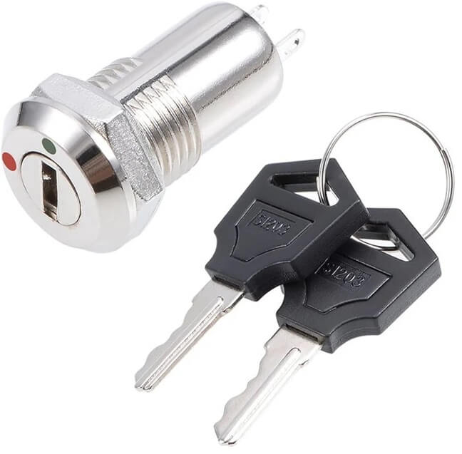
So while you enter the office, you disable power through the key lock, then when you leave the office you can arm the device back by unlocking power to the device…you must do the above operations while the door is in the closed position…:
Thanks I appreciate it.
ΟΚ THANK YOU I WILL TRY IT WITH A VIBRATION SPRING
Hello,
I’m looking for a simple vibration alarm circuit. The one I can’t find is the one that, when activated, sounds for a certain amount of time, which I can adjust to set how long it will sound.
Not a circuit that delays activation, but one that sounds for a configurable period once triggered.
Hello, you can try the first circuit from the following article. You can adjust the C2 value to change the delay OFF timing of the relay:
https://www.homemade-circuits.com/simplest-sound-activated-relay-switch/
Hi there great little circuit. Instead of using the reed relay this could be hooked up to either the dome light or door open lamp indicator on the dash as an effective car alarm. Am I correct in saying that. Also using a higher rated capacitor would that keep the alarm sounding longer until discharged.
I could be wrong and I apologise for my lack of knowledge but are learning. Just wanting to build a simple but effective vehicle alarm.
Hi, you are absolutely right with your assumptions. That would certainly work.
You can tweak the 1000uF capacitor or the 22K resistor or both to optimize the output time delay, as desired.
I read your artical on magnetic switch alarm What im doing is setting up a 12 volt door alarm and need to know what timer I need. I want the alarm to remain on for a set time after switch is tripped even if door is closed and switch is reset I need the alarm to continue for preset time. Would a simple time delay switch work?
The mentioned feature is already included in the design. The 1000uF capacitor ensures that the alarm runs for some time even after the door is closed
What is the use of transistor and why it generates low frequency
Pls solve my query
transistors are not generating any frequency, the alarm is supposed to have built inbuilt oscillator.
Hello Sir,
On Door Security Alarm Circuit.
1. How would I calculate the size of Resistor and Capacitor to give an approximate ON time of 10 minutes once the alarm has been activated
2. What is the maximum safe current the transistors BC557 and 2N2222 can carry
Any advice will be welcomed
BC557 can handle 100ma, 2N2222 1Amp on heatsink
Hello David,
I am sorry I do not have the formula for RC network, you will have to find the right value through practical testing. By the way 10 minutes is not feasible in the above design unless you add another transistor in it…
hi sir, can u please help me out with a breadboard version of the door alarm circuit
Hi, Jonathan, breadboard is not recommended for such a basic and a small design, you must use a strip board and solder the parts instead…
Sir please help me I want a timer circuit it will Turn the relay on 15 second And Turn the relay OFF 15 Seconds Continiusly
Sir would you please discuss remote controlled calling bell next,? If you do it will be very helpful. Regards.
Debasis, I already have it in my website you can search it through the search box…
Thank you sir for this circuit
Sir… Can u please help me out with a project proposal on DOOR OPEN CLOSE ALARM CIRCUIT.
you are welcome Chisom
Hi sir, i wanted to ask you if it is possible to build an homemade flashdrive( i.e any storage device) or not. And pls i need your help.
Hi Tun, according to me it's not possible…