Learn how to build a simple car burglar alarm circuit right in your home.
The circuit is built around a few trivial components and yet proves to be totally fool proof with the security of car accessory to which it has been integrated.
You certainly won’t like waking up just to see your car audio being cleaned up by a smart intruder.
A tiny circuit of a car burglar alarm system described here can surely guarantee you a total piece of mind as far as the security of your car accessories are concerned.
Why a Burglar Alarm is Necessary in Cars
How important is your car to you? Well, you may say that’s a ridiculous question, off-course a car is too important for any individual.
In fact it’s like a home to many and an indispensable part of life.
Truly, a car is quite comparable to a house as today it is perfectly equipped with comforts equivalent to that present in a house.
Take for example, a music system – probably, the one that may be installed in your car is much sophisticated than the one situated in your home.
However, did you know that if it’s so valuable to you, it can also be to many other eyes….constantly hovering around vehicles to grab and run off with one your most valued gadget.
Yes we are talking about burglars especially trained for robbing expensive car accessories too softly and swiftly for anyone to notice.
Before you feel too enlightened and head for the market to get a security system installed in your car, I would like you to give it a rethink - regarding a simple 1 dollar electronic car burglar alarm circuit idea that would provide the same level of security to your car audio or any interior accessories for that matter as an expensive $100 system would offer.
Let’s read the following discussion to know regarding its circuit description:
How this Simple Burglar Alarm is Designed to Work
We know that normally the body or the metal chassis of any vehicle is kept at ground potential and is done by connecting the negative of the battery to the body of the vehicle.
Thus it acts like a huge ground or “earth” and helps to absorb all electrical interferences. This particularly helps the audio systems to produce clean outputs.
Moreover this also provides an easy and short access to all electrical gadgets to the negative line as their negative contact can be directly fixed to ground avoiding cumbersome wiring.
The above grounding feature proves to be an effective pick-up point for the present circuit.
Basically, a trigger point from the circuit is attached to one of the fitting bolts of the car audio system.
As long as this point of the circuit is held at the ground potential everything remains normal.
However, if a burglar tries to uninstall the system and detaches the bolt, the circuit fires and sounds the car horn alarming everybody around, and you of a possible theft.
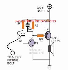
The circuit of a car burglar alarm system shown alongside is brutally simple and easy to understand. Transistors T1 and T2 are configured as current amplifiers.
As long as the junction of C1 and R1 is held at a ground potential (as explained above) T1 is inhibited from conducting.
However the moment this connection gets disconnected from the ground potential, positive voltage gushes in through C1 and triggers T1 into conduction.
This immediately charges C2 and also triggers T2 which ultimately sounds the horn and the alarm.
C1 makes it sure that T1 is allowed to conduct only for a second, which happens to charge C2 fully.
C2 along with R2 and R3 forms a kind of a short duration timer and keeps the horn active for a few seconds, enough to rattle the burglar and make him flee forever.
Parts List
- Resistors are 1/4 watt 5% CFR
- R1 = 10K,
- R2 = 4.7K,
- R3 = 100Ω 1 watt,
- C1 = 100µF/25V,
- C2 = 1000µF/25V,
- T1 = BC517
- T2 = TIP127,
- FLEXIBLE WIRES, LUGS, SUITABLE ENCLOSER


Questions & Answers
How to make a kill switch integrated when a thief brakes into your vehicle pushes the start button and the vehicle will not start and he get a loud speaker notice that says prepare to die He immediately vacates the vehicle thanks
The kill switch can be configured as explained in the following article:
https://www.homemade-circuits.com/simple-and-cheap-vehicle-immobilizer/
For the voice message you can use voice recorder module or circuit and configure the “play” switch with the ignition button
Hi, I was thinking of a simple system that ties the door switches with the horn so that when the door is opened the horn sounds. Add an on off switch in the grill to arm and disarm. If they are going to smash the window to get to the stereo, why wait till it is half out. Any thoughts?
You can wire the horn with your car door switch exactly as it is done for your dome lights. The positive from the battery goes to the positive of the horn through a arm/disarm switch, next, the negative of the horn wire connects with the door switch, that’s it.
Couldn’t edit my comment but the thought behind this is I have a 2003 S10 with no power anything that just cost me $300 deductible on my insurance because someone tried to steal it.
Do you make a video on How to make home made car alarms