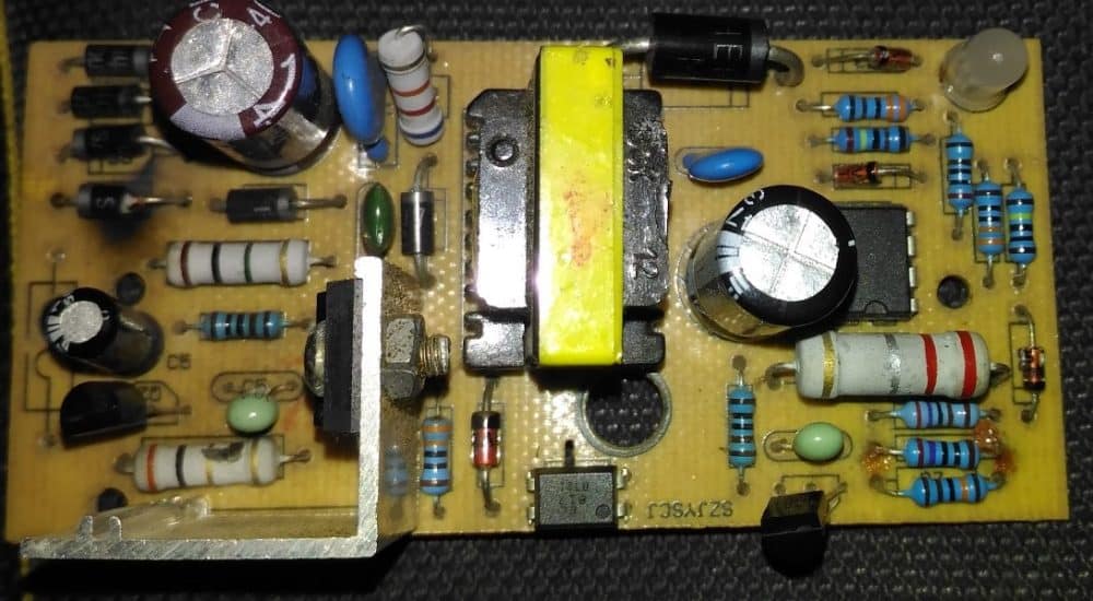
In this post we try to diagnose a burnt SMPS circuit and try to troubleshoot and repair the circuit. The shown unit is a cheap readymade Chinese make SMPS circuit. This article is written as per the request made by Mr. Kesava.
My SMPS got Burnt
The below attachment is 12v 1.3 amps SMPS for charging Agriculture Sprayer..If charge full the green led will glow...If charge low the red led will glow...
But now this charge not working...And i check inside , The AC input bridge rectifier IN4007 1diode got damaged...i replace it with new one diode..Now the new diode also damaged....Pls guide me sir....
In our area shop..this type of chargers are not available sir...But my aim is not to buy new one..i itself want to rectify with u r guidance sir....Pls help me sir....
Sorry for bad english.I'm not good sir...
Thanks & Regards N.Kesavaraj
Troubleshooting the Problem
Hi Kesava,
It's most probably due to a burnt mosfet, the one which can be seen on a heatsink. You can try replacing it with a new one, and also make sure to change the adjoining 10 ohm resistor which also looks like it is burnt.
Regards.
Repairing the SMPS Circuit
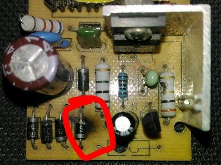
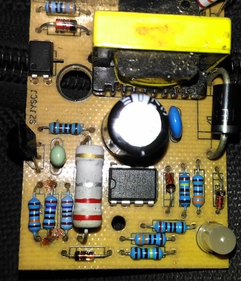
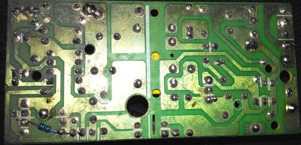
Referring to the images above, the primary side of the unit appears to be the popular 1 amp 12V SMPS adaptor using a mosfet based switching design, and includes an opamp based auto cut off charger section at its secondary section of the board
From the first two images we can clearly see that one of the diodes being completely blown apart, and responsible for shutting down the entire circuit board.
A bridge rectifier can be normally seen at the beginning of any SMPS circuit and is introduced primarily for rectifying the mains AC to a full wave DC, which is further filtered using a filter capacitor and applied to the mosfet/inductor stage for the intended flyback primary side switching operation.
This primary side switching causes an equivalent low voltage pulsating DC to be induced at the secondary side of the transformer, which is then smoothed using a large value filter capacitor at the the secondary side for acquiring the final stepped down SMPS DC output.
From the image it appears that the entire design is based on a mosfet, inductor switching topology wherein the mosfet becomes the main switching element in the circuit.
The diodes in the bridge rectifier appears to be the normal 1N4007 diodes which are capable of handling not more than 1 amp current, therefore if this 1 amp value exceeds the diodes can get ripped through and damaged.
The diode might have burnt due to a high current passage which in turn might have happened due to a stalled mofet inductor operation. Which means that the mosfet might have stopped osculating causing a short circuit through itself, allowing the entire AC to go through the components within the input supply line.
How to Repair the SMPS Circuit.
The shown burnt SMPS can be repaired with the following simple steps.
1) Remove the mosfet from the PCB and check it with a multimeter
2) Without any doubt you will find the mosfet being the faulty component, so you can quickly go for a replacement of the same using a correctly matched mosfet
3) After changing the mosfet make sure to change the burnt rectifier diode also, and ideally change all the 4 diodes in the bridge, to ensure no weakened diodes are present in the network.
4) You may also want to check if there are any other parts such as resistors or thermistor that may look suspicious and if any replace them with new ones.
5) Once all the doubtful elements are replaced it is time to switch ON the SMPS for the final verification.
However this must be done with a series protection load in the form of a series incandescent bulb to make sure that the circuit does not blow of due to some other hidden fault. A 25 watt bulb will be just good for safeguarding the unit from any catastrophic circumstances.
6) On switching on the SMPS, if the the bulb does not glow, it would probably indicate all's well and the unit has been repaired successfully. Now you can feel free to check the output voltage of the SMPS with a meter and confirm that it is producing the right readings.
7) Finally without removing the bulb connect an appropriately rated DC load and check whether it is working correctly or not.
8) If everything seems to be working normally you can remove the series bulb, and repeat the testing process, but make sure to include a small fuse in series with the input supply permanently.
9) However in case the bulb shows a bright glow, would indicate a serious problem persisting in the SMPS circuit and will need to be investigated afresh, this may be done by first switching off the unit and then checking each and every component in the primary side of the trafanformer.
10) The components which needing a recheck will be fundamentally the ones which are prone to high voltage and current damage, such as small BJTs, diodes and low value resistors.
11) The components which can be left unchecked are the ones which are adequately rated and are able to protect itself from from high voltage and current inrush. These may include high value resistors above 50K, or low value wirewound resistors above 1K.
Similarly, capacitors which may be rated above 200V can be left unchecked unless one of these look somewhat damaged externally.
Testing for a Burnt Inductor Transformer
Every SMPS circuit will essentially include a small ferrite transformer, which this part can also possibly become the cause of a burnt SMPS circuit, although the chances of a damaged transformer can be too remote.
This is because the wires inside the inductor might require some time to burn, and before this can transpire the other more vulnerable parts such as diodes and transistors would be forced to blow off ,preventing any further damage to the inductor.
So basically you can be rest assured that the transformer is the one element which might be the safest and the undamaged part in a given faulty SMPS circuit.
If in a rare event the inductor burns, this would be distinctly visible from the burnt insulation tape which may be also melted and stuck with the winding. An SMPS with a burnt transformer could be virtually irreparable, because a burnt transformer would mean most of the elements burnt out, along with PCB tracks uprooted. Time to buy a new SMPS unit.
The secondary side mostly will not require any checking as it is isolated from the primary and can be expected to be aloof from the dangers.
Well, this concludes this article explaining tips to repair an SMPS circuit, if you think I have missed some crucial points, or if you have something important to add in the list, please tell us through your valuable comments.
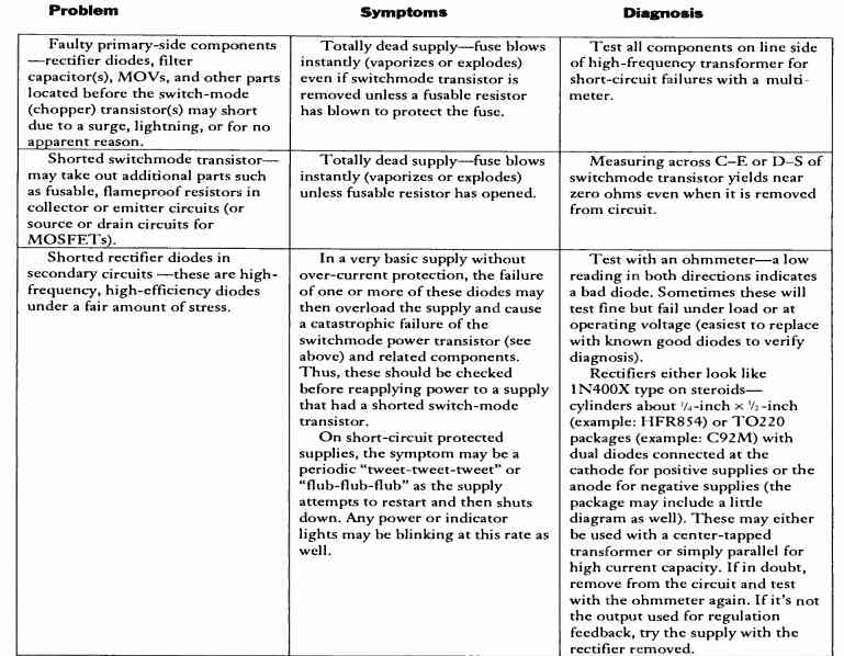
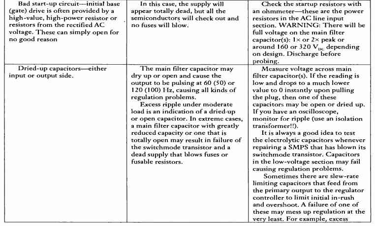
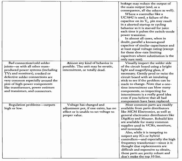
More Tips and Solutions to Repair SMPS can be studied in the following table:


Questions & Answers
Hi there:)
Got an idea to build an spot welder,but i have problems with timing the welding.Manual drive gives too long time….
Im in need of double shoot 10-100ms timings.The first shoot actually cleans the spot for the second final weld.(this is also an idea….hoping to work)
Probably Arduino fits for that but beeing an w noob programmer(i can only modify values in existing program),im asking your help:)
Till now i didnt get any usable program for Arduino doing what i want.
Ill use optotriac and 25A triac to drive the microwave oven transformer primary winding(hoping to bee a good idea).
Thx in advance
Hi there, it can be easily implemented using a simple IC 555/4017 circuit and in fact much more effectively than any other method. however for the Arduino version you may refer to this concept which you can modify appropriately as per your specs
https://www.homemade-circuits.com/arduino-spwm-generator-circuit/
the code is designed to produce multiple pulses, you can eliminate all the steps except a couple of them as per your preference.
very informative
thanks
This is so timely and so helpful….thanks swagatam.Your contribution to humanity for free is what makes life interesting..God bless you
It’s my pleasure kentro, I appreciate your response, God bless you too!
Dear Sir, do you have schematic diagram of panasonic microwave inverter?
Sorry Agus, I do not have it at this moment!
Thanx Thanx Thanx. Very useful & simple to understand. Appreciable. Thank you again.
You are welcome Saeed!
Hi bro your information was educative but can u give examples of switching mosfet that can be used.
Thanks Coach, typically all n-channel mosfets whose Vds is above 400V, and Id above 1 amp can be used for SMPS applications
Can you give circuit Diagram for this ?
I have many faulty circuits of this same design but I am stuck to trace circuit without Diagram.
so Please made diagram once…
and tell me how to find Auxiliary, Main primary winding in ferrite transformer.?
thanks…
Here’s one related article that may help you:
https://www.homemade-circuits.com/12v-24v-1-amp-mosfet-smps-circuit/
that is different from this. I had seen this before make comment on this. I didn’t recognize properly so i told to you.
Sorry, I don’t have the exact layout details which is shown in the above article.
dear sir! i have made an smps xformer using PQ3230 core according to my specification for a chinese battery charger. it gives Vout = 14.2vdc & Iout = 13amp this is right for my design. but every time i face the problem of power mosfet starts heating up even without load. i have no idea why this occur. the design is using uc3843 oscillator, Vcc of uc3843 is 28vdc & pulse voltage about 5vdc. is there any solution to stop heating of power mosfet without load?
Dear sheraz, a MOSFET or any transistor will heat up when a higher amount of current is passed through it. In your case may be the transformer winding is not matching and creating higher current to flow through the mosfet. You can try increasing the primary turns or increasing the frequency of the circuit, may be by changing the frequency determining RC capacitor or the resistor.
Hi Swagath,
I need a help to sort out the cause of damage for a MeanWell SMPS, ELG-150-48 IP67 type. It is used in a LED RGB colour changing flood light as power source. After 2 year of usage, SMPS is getting damaged frequently. Out of 80 nos, I got 15 pcs damaged already. When I opened the SMPS and inspected, its input side, fuse is blown, MOSFET is short circuited and one resistor, and one diode is damaged. The load connected to the smps is max110 Watts.
please help me to find the cause of damage.
Hi Rasi,
assuming the SMPS design is flawless, and there’s no overload at the output side, then the most probable cause could be a higher input voltage, that may be causing a lot of stress on the MOSFET.
You can add a high voltage cut off system with the mains DP line set to trip at 260V. This would help you to understand if the input voltage is responsible for this.
Thank you for quick reply. The maximum voltage capacity of the SMPS is 300V V AC. Is there any chance for the stress on MOSFET is because of the line surge?
300V is the breakdown value, so even at 260V the MOSFETs could be working under some stress, and if continued for long can result in device failure, adding 260V cut off will help us to understand whether it’s indeed a voltage issue or something else. If the cut off trips frequently, then it’s definitely voltage issue.
thank you so much.
Dear Swag, first of all thank you for your patience and knowledge. I have a problem with led driver smps board 12 v 2A. How do we test separately isolated primary and secondery regions of the board. that is, after removing transformer, how can I analyze the two circuits with another suitable source to see the components’ condition? I mean that I want to drive two circuits separetly by external portable source or another circuit that can be useful for testing secondery side. And one more thing. After removing primary winding what happens when replaced by two serial ordinary bulb that works 220vac to see the primary side is oscillating or not. Purpose of doing so is to protect the semiconducters from burns or shortened. Thank you…
Dear Ercan, the transformer becomes the integral part of any smps so it may not be possible to analyze the working of the components in smps mode without it. The only way to confirm the parts is to remove each part and check them with a meter. Also since the trafo needs accurate calculations, it may not be possible to use any other source as a replacement. Using bulb is not possible, because oscillation will initiate with an inductor only…
Hello Swagatam,
I had a brand new 12v, 2A SMPS worked properly with 12v and 1.6A load. (Some components are mje13007, 12v zener, 8050S transistor). I doubled the secondary wire by adding same strand. (It was 18t of 0.5mm originally). The aux. wire was 8t of 0.2mm which i added to it perfectly.
But it is not working now and just show 1.2v on multimeter. And the LED is not glowing anymore. Where did i do that wrong?
Thanks
Hello Mah, rewinding an smps transformer with a different gauge wire should not cause any problems in the smps. Something else might have gone wrong, for example the turns might not be smoothly wound, or the E cores not fitted correctly as in the original case, or pin configuration changed…..you can try putting the winding back as it was done originally and check the results.
Forget to say,
I didnot changed any other components like;
2A Fuse, MB10M rectifier diode, 6.8uf/400v rectifier cap, 470uf/16v and the zener.
Bro use same value of components and check the pin of trangister and check if any capacitor is damage or not and also see any other components are damage or not ok ????????
I have alot of defect switching power suply 12V DC output .. Mostly defect 10A and 20a . I used it for cctv camera.
Pls advice me what is mostly parts on it defect and how to trouble shoot fast easy and simple.
Thks n rgds
Ahli cctv jakarta
It is mostly the MOSFET that burns due to overheating or output short circuits….make sure to add a feedback loop if already not present, to control the current and prevent short circuit burning of the devices.
Thank you for your soonest reply to my questions about SMPS Troble shooting,
sorry i dont understand this “make sure to add a feedback loop if already not present, to control the current and prevent short circuit burning of the devices. ”
WordPress
4:18 PM (25 minutes ago)
How to Repair a Switch-Mode-Power-Supply (SMPS)
It is mostly the MOSFET that burns due to overheating or output short circuits….make sure to add a feedback loop if already not present, to control the current and prevent short circuit burning of the devices.
Feedback loop is a feedback from output of the SMPS transformer to the MOSFET or the IC side of the SMPS through an opto-coupler, this stage is normally always present in all SMPS except a few cheap ones where this is not present.
Cheap SMPS mostly burn due to overload, switch ON power surge. So it must be protected with a feedback loop and an NTC/MOV suppressor at the input AC side.
a snubber circuit would help . wouldn’t it ?
i have gone through various sites including yours. i have JBL System called DSC-500 Purchased in 2004. i did not use for long time. Now when switched on the system goes on & off.
First it works for 25 seconds & switches off. Then on wards switches on & off every 8 seconds.
Its problem with SMPS. I am electrical engineer retired. i isolated only SMPS & Connected to power. Same thing happens on & off. I checked all caps inductors etc. Not able to make out. May be its with IC main voltage regulator? IC, NCP1002?
It could be due to auto shut down feature of the SMPS, because of over-voltage or lack of load. You can try putting some appropriate load and check the response
What causes the smps to have intermittent power problem
After carrying out all the faults mentioned that replacing mosfet and all I am getting fluctuating voltage 22v at IC 3844 pin 7 and I cannot trace the faults.
What will b the problem
What voltage are you getting at the output of the transformer? Is the IC and the MOSFET heating UP?
Hi, I just came across your article on smps and I believe you can be of help to me. I have a 21″ LG crt TV that shows red standby light steady but won’t power on. I checked the primary main filter capacitor but got 250v and the AC input is 220v.please can yo guide me on how to repair it. I will be very grateful. Efi Philip.
Hi, I can provide only the general tips about troubleshooting, I cannot specify the exact fault in your circuit because each SMPS has a different circuit configuration, and part layout.
hi
i wanna repair a siemens smps three phase to 24v 40A
please tell me how can i find the circuit diagram
thanks
sorry, I have no idea about it!
Hello i have a smps ac to dc 12v 10 amps but it got failed and both -ve and +ve are showing power and i checked with circuit but has no blown component canyou help wt could be the failure at
Hello, without understanding the exact issue with the SMPS it can be difficult to judge the fault.
Hello,
I have no output on the secondary side of this smps power supply.
It has two separate output connector. The larger one has multiple voltage pins from 3.5 to 24 V and the smaller one across from it is 3.75 volts. Both show no voltage.
I have 167VDC at the separation wall and the switching N-channel FET I checked independently and it seems to be switching just fine. So I assume the voltage on the primary side is pulsating since a multimeter doesn’t show pulsating voltage.
On the secondary side there is no voltage showing from any legs of the transformer to the middle leg of schotkey barrier diode, the middle leg is common and such diodes are desiged with two diodes facing each other and look like a trasistor.
I am pressed to blame the barrier/chopper or whatever kind of transformer it is called but I sure don’t see any sign of burnt of anything on it.
There are of course two of them, one for each output.
There are also 4 optocouplers at the border.
I can not concieve of checking other things although I have checked the capacitors and other diodes and transistors, they are seem to pass measurements. Not sure what to blame except the transformers.
Any suggestion would be appreciated.
I am not sure if I can put any picture in the comments. There are no attachement options
Thank you very much.
Hello, First you will have to confirm whether your SMPS primary side is oscillating or not? Normally SMPS use anywhere between 20 kHz to 200 kHz frequency at the primary side.
If the primary side oscillates, only then the voltage will be induced across the secondary side of the SMPS.
Mulltimeters will be able to detect the oscillating frequency if the meter has frequency selection facility
Transformers normally don’t burn rather it is the mosfet or the IC which burns, and the oscillations stop, which in turn causes no voltage to be available at the secondary side.
….Please confirm the frequency at the primary side, it should be between 20 kHz and 200 kHz
I tested the switching transistor independtly by suppling 4 volts, with a .1uf cap between the collector and the emitter. And a 40K resistor from voltage source to the collector and then another 40K from the collector to the gate, leaving the gate out as a sort of antenna.
As I approached the gate of the FET with the gate wire, voltage would drop and moving it away, voltage would rise at the ( voltmeter that is). I had the voltmeter hooked up at the collector and the emitter of the FET.
Since I don’t have an osciloscope.
If that means it is pulsing or not.
Aside from that I most likely measured the voltage of 167VDC where I found it and not where it counts.
There are two driver transformers.
Before one of them there are two ceramic caps, and the other 1 cap, film caps I guess they call it. .01 uf and 1.25KVDC.
When I tested their farad by taking them out, they seemed to spec. I took them out because in the circuit it was reading strangely high or eratic.
But here is what I found out.
I decided to charge them. They don’t hold charge.
So two things for now:
If I don’t have that high of a voltage ceramic caps, what value I can get away with just to see if they were the problem?
And secondly did my testing of switching mosfet ( NEC 2SK2369) have any meaning, that it is working?
[Come to think of it. The transistors that feed those ceramic caps seem to be related to chopper regulator DC to DC converter FET (Toshiba 2SK3314). Should I check these and there are two of them instead of them and the one I checked above (NEC 2SK2369) does not count assuming how I checked is meaningful in terms of pulse. The reason I am saying these are the ones that is related is because their collector or one of them pins go to those capacitors leg on the one side when I checked the resistance as I was tracing]
The capacitors will be mostly good, since they are rated with adequately high voltage. Mostly it is the transistors and the diodes which can go faulty. So you will have to check all the transistors and diodes by removing them from the PCB. Also, initially disconnect the opto coupler links and check the working, because if the opto coupler feedback is faulty it might keep the main transistor switched OFF.
The main thing is that if the primary side oscillates, this frequency will be delivered to the transformer and the transformer secondary will also show the output voltage, so it seems your mosfets are not switching. The switching frequency can be tested either through a frequency meter or an oscilloscope.