In this post I have explained how to make a simple variable power supply circuit using transistor 2N3055 and some other passive components. It includes variable voltage and variable current feature, fully adjustable.
Main Specifications
1) Adjustable from 0-30V, 0-60V, and 0-100V, and 500mA to 10 Amp as per user preference
2) Short Circuit Protected when mounted on proper heatsink
3) Ripple free, with less than 1Vpp
4) Output is Stabilized and filtered DC
5) Short circuit LED indicator
6) Overload Protected
Introduction
A power supply circuit that does not include the features of a variable voltage and current control can by no means be considered truly versatile.
A variable workbench power supply circuit I have explained in this article is not only specified with a continuously variable voltage control but is also equipped with the feature of overload or continuously variable current control.
Circuit Diagram
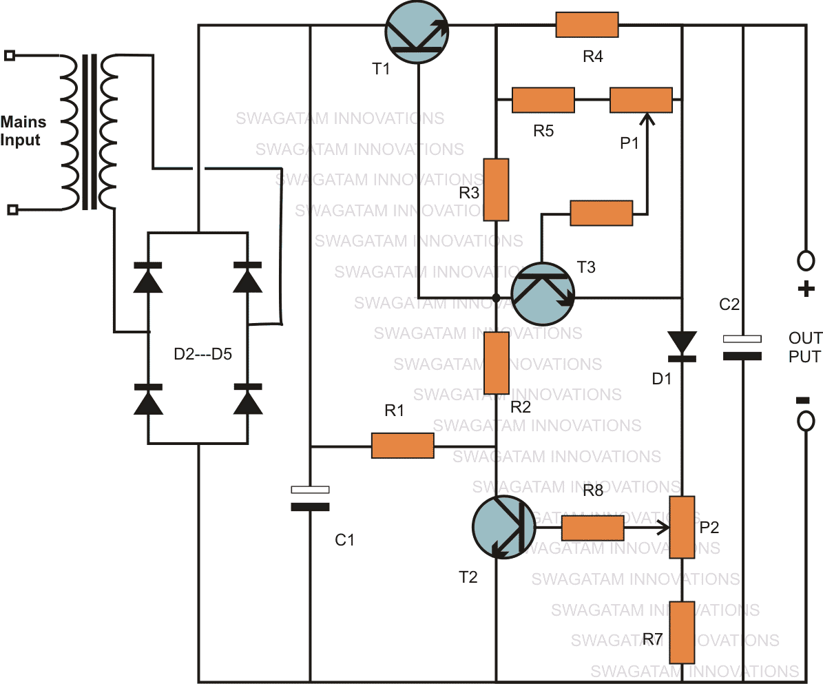
How it Works
A keen look at this 2N3055 based variable voltage current power supply circuit using transistor 2N3055 reveals that it’s actually only an ordinary stabilized power supply circuit, however it yet still provides you with the proposed features very efficiently.The voltage variations are made by using the preset P2, through a feedback configuration employing the components D1, R7, T2 and P2.
The inclusion of D1 makes it sure that the voltage can be lowered right down to 0.6 volts, which happens to be the forward voltage drop of the diode.
If any other specific minimum value is required then the diode can be replaced by zener diode having the required specified value.
Therefore in this variable power supply circuit using 2N3055 transistor, the transformer being a 0 – 40 V, the output becomes variable right from 0.6 to 40 volts maximum, that’s very handy indeed.
For implementing the current control feature, T3 along with P1, R5 and R4 are involved.
The value of R4 is specifically becomes responsible for defining the maximum allowable output current.
P1 is set to choose the maximum range within the value that’s marked or identified by the resistor R4.
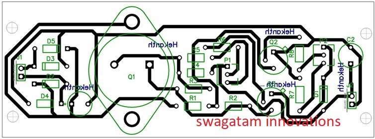
PCB Design
Parts List
- R1 = 1K, 5 watt wire wound
- R2 = 120 Ohms,
- R3 = 330 Ohms,
- R4 = to be calculated using Ohms law.
- R5 = 1K5,
- R6 = 5K6,
- R7 = 56 Ohms,
- R8 = 2K2, P1,P2 = 2k5 presets
- T1 = 2N3055,
- T2, T3 = BC547B,
- D1 = 1N4007,
- D2, D3, D4, D5 = 1N5402,
- C1, C2 = 1000uF/50V,
- Tr1 = 0 – 40 Volts, 3 Amp
2N3055 Pinout Details
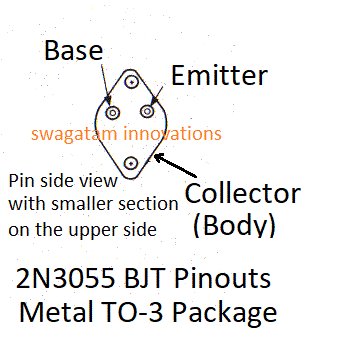
If you have any doubts regarding this variable voltage and current power supply circuit using transistor 2N3055 circuit please do not hesitate to ask then through the comments below.
Original Transistor Power Supply Diagram:
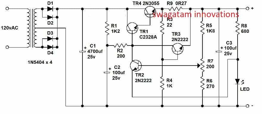
The above design was inspired from the following circuit which was designed and presented in the elektor electronics magazine by the elektor engineers:
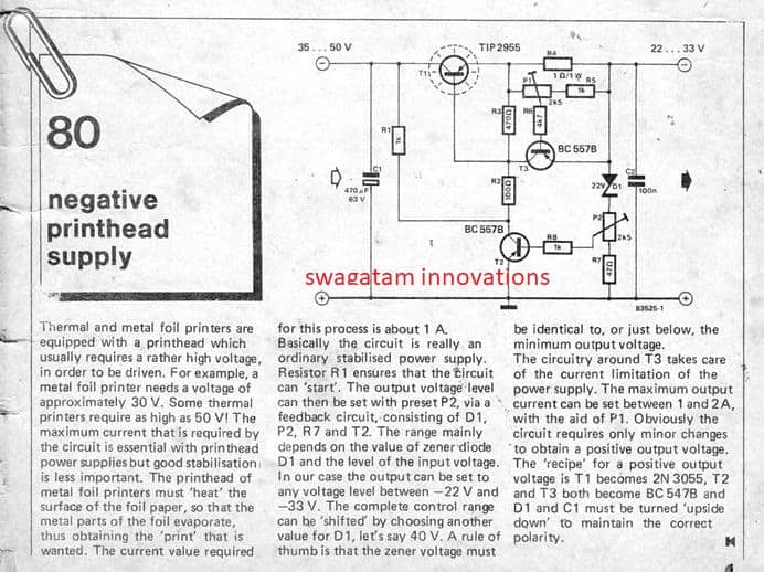
Simplified Variable Power Supply Design using 2N3055 and 2N2222 Transistors
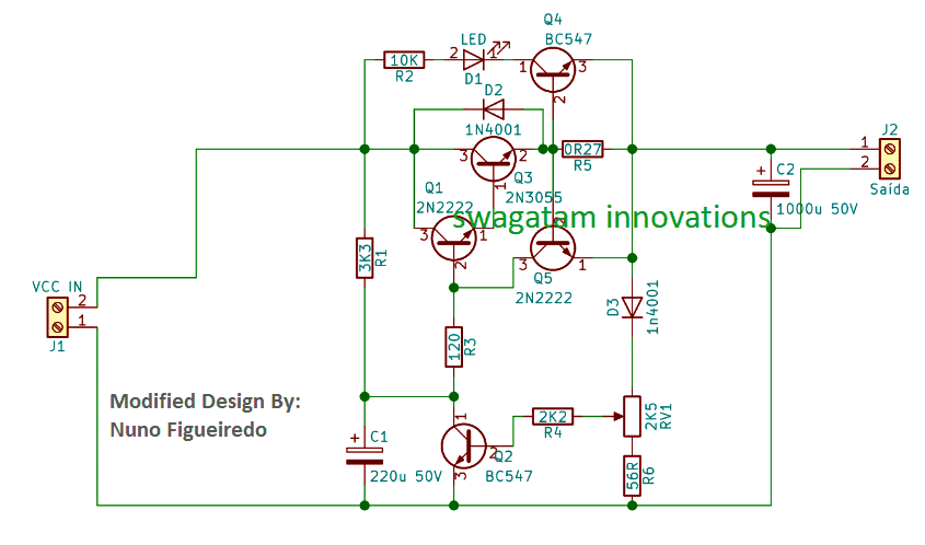
The above designs were assessed and simplified with more effective results by Mr. Nuno. The revised and simplified design can be viewed in the following diagram:
The design features an over-current shut down with LED indication.
Video clip of the tested prototype:
For PCB Design and other Related Data, you can Download the following ZIP File:
PCB Design for the above Circuit
Another Similar Power Supply Design as Referred by Mr. William C. Colvin is presented below for the viewer assessment:
2N3055 Wide Range Variable Voltage Regulator
The key highlights of the circuit are: wide range output: 0.1 to 50 volts excellent load regulation: 0.005% between 0 and 1 amp, decent line regulation: 0.01%, reduced output disturbance: superior to 250 microvolts.
The broad output selection is implemented with thehelp of the integrated circuit CA 3130, that is able to work even with a zero volt input/output differential. In addition, higher extension of the output range becomes feasible through the inclusion of T4 between the IC and the series pass transistor.
The high gain as a result acquired enables a superior level of regulation, and the T1/T2 Darlington pair offers a adequately large current boosting. T3 works like an output current controller.
When P1 is rotated totally anti-clockwise, T3 restricts at 0.6 amps. The limiting circuit becomes inactive when P2 is moved completely clockwise. The regulator circuit specifically operates in the following manner.
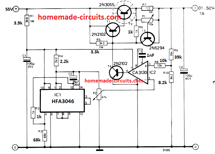
The IC CA 3130 analyzes the output voltage given to the non-inverting input with respect to a reference voltage at the inverting input.
The output voltage of the regulator is reduced with a potential divider to protect against damage to the IC.
The reference voltage is determined by P2, which needs to be a top-notch part, since any kind of noise upon its slider arm will probably be transferred to the regulator output terminals.
A additional IC, HFA3046 , offsets the reference voltage intended for temperature variations. The IC is made up of 4 transistors applied as diodes or zener and another transistor for cutting down the output impedance of the reference circuit.
The reference IC furthermore provides a stepped down supply voltage for powering CA 3130. This feature necessitates the use of each ICs in the regulator stage; if IC1 is removed can result in the break down of IC2. Each of the transistors shown in the diagram must be rated with a breakdown voltage of a minimum of 55 volts.
High Current Variable Power Supply
In this high current linear power supply circuit, we have used a 2N5686 transistor instead of 2N3055, so that the circuit is able to deliver a minimum of 10 amp current, and the preset P3 could be used to adjust a current range of 10 amp.
The power supply itself is pretty straightforward to construct. An IC LM329 provides a steady reference voltage of 6.9 V.
P4 is a potentiometer, and this pot is utilized to determine the output voltage using a preset potential divider P2-P4-R2. The power stage of the circuit is made up of IC1 and T1, which operate like an operational amplifier when it comes to positive voltages (negative voltages are not relevant here, obviously).
This non-inverting amplifier is built using an combo of op amp, P1, R5, and R6. This indicates that the voltage at P4's wiper is proportionate to the voltage across the output terminals.
P1 is a potentiometer that controls the peak output voltage, while P2 is used for setting the minimum output voltage from the power supply.
Preset P3 is used for setting up the maximum current limit of the output.
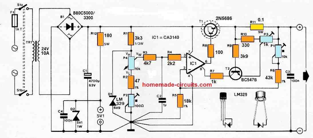
R11 converts the output current to a voltage to accomplish this. When this voltage (controlled by P3) is large enough to turn on T2, the circuit's voltage regulation is superseded by current regulation through IC1's strobe input. The maximum current that can be adjusted is from 0.8 A to 10 A, depending on how the controls are adjusted.
When the output of the power supply are short-circuited, the current must not increase above 25 A to prevent T1 from being damaged and due to over dissipation. The circuit setting up is not complicated. To begin, adjust P4 to highest possible resistance and wait about a minute until Z1 and IC1 reach their typical working temperatures. Next, adjust P1 to get a 25 V output voltage.
Finally, tweak P2 to provide a 250 mV output voltage by setting P4 to lowest resistance. The lowest output voltage of 250 mV was selected on purpose to guarantee that the individual parts always are able to work with a linear region of their characteristics. There are a couple of things to remember here: the earth lines must be routed exactly as shown in the schematic, and T1 must be installed on a 1.5 K/ W heat sink.



Questions & Answers
can help for selecting R4 resistor
can help to select R4 resistor
R4 = 0.6/desired max output current
R2 can never burn, because it has protections in the form R1 and R3, please check the connections, something might be wrong.
I have built and used this circuit for over 5 years.
where can i put a little milliammeter and a little voltmeter to view the voltage?
voltmeter should be connected right across the output (+)(-) terminals while the ammeter should be connected in series with the positive (+) output line.
Good afternoon sir!
1. What is the wattage of resistors?
2. If 3 amps is my max current o/p, do I still need R4? and if yes is my calculation correct
– 0.6/max current output (which is 3 amps) = 0.2 ohms (and how many watts)?
3. Can I add fuse and what rating and where will I put it?
4. and if possible, can you add another feature
– variable wave (ex. sine, square, triangular, etc.), and
– short circuit protection
It's okay for me if the cost rise.
thanks. 🙂
eshkariel,
all resistors are 1/4 watt except R4.
R4 is for protecting the load, it may be included if required.
yes 0.2 is correct, wattage will be 0.6 x 3 = 1.8 watts or 2 watts
you mean function generator"? you can get plenty of such circuits online, just google "function generator"
I am building one like this.
In your part lists R1 is 1K 5W wirewound, but in this comment section you said that all resistors are 1/4W, which one R1 should be? It is hard to get 5W cement resistor here, is it okay if I wound 10 of 10K 1/2W in parallel to get 1K 5W?
Then if I want to connect digital voltmeter-ammeter, which has 3 large wire (yellow-red-black) and 2 thin wire (red-black) which is supposed to be independent power when the voltage is lower than the voltmeter power rating, how should they be wired? Thank you
the resistors which not specifically mentioned are all 1/4 watt.
you can use 1K 5 watt carbon or metal, wirewound is not essential. higher wattage resistors than 5 watt will also do.
yes 10nos of 10k in parallel will do.
I am not sure about the meter connections…it'll need to be confirmed by you through physical testing
Okay. Hope I don't smoked my meter. I will search more information on the net and post back here when I've done. Thanks in advance.
It works. I've got 2.18V to 14.15V. Only that my digital voltmeter won't light when the voltage is below 4V. The transformer I used has multiple output, I also try connecting its thin wires to the lower voltage output to get an independent power source, but still can't light up the voltmeter below 4V. I will try another configuration later. All of all, thanks for this circuit.
OK, thanks for updating the info
what I meant in #4 is that you can change the wave of the power supply, like if you want 12v square wave for a siren or a sine wave for lights , etc… and how about the fuse? or short circuit protection?
yes wave making circuits are called function generators.
fuse could be used and must be rated at sightly higher than the specified load current.
Sadly transformer rated at 0-40v 3 amps isnt available anywhere in our downtown in Bacolod…the only transformer with rating of 3 amps is in 0-36v. Can I use this? What modifications will I make? please help me..Thanks! 🙂
yes, it will work nicely, no mods required
Hi Swagatam Majumdar,
I´ve searched for a basic voltage and current control PS, as a replacement for my "gone wild" lab PS. As i do want to build it up myself and do it all discrete, yours looks like just what i need…I already got two toroidals each is 2x18V/5Amps. So i´ll do a breadborad and see.
Thanx for this post,
TubiCal
This circuit looks to be exactly what i'm after (variable voltage and current) for making an electro-etcher.
I'd like to be able to find the minimum volts necessary for current flow and then increase the amps without increasing the volts.
I've been trying to draft this in Qucs (Quite Universal Circuit Simulator). It doesn't have potentiometers so I've just put resistors either side of where the pot would be (their resistance adds up to 2.5k).
I'm not getting the results expected. Any chance you could help out with parts that will allow up to 24V and 4A?
R4 could be calculated by using the formula 0.6/amp, so for 4amp max it could be around 0.6/4 = 0,15 ohms @ 0.6 x 4 = 2.4 watts, ideally this could be a 0.1 ohms/3 watt resistor
Frankly, I don't believe in simulators, these are like blind persons with sticks, not reliable in most of the cases… the above design has been tested by me, and it worked quite well as per the proposed specs.
Thanks for the fast reply. I like to see things simulated before diving in, but I guess I should just break out the soldering iron.
sure, that would be a better approach….
Hi Swagatam
Couldn't a TIP41C (6A device) be used instead of 2N3055 for maximum current of 3A or 5A?
Hi Abu-Hafss, yes it can be used but 2N3055 is 15 amp rated so a TIP35 would be more appropriate.
can i use multiple transistors and if i can what changes do i need to make
you can use an outboard transistor with the 2N3055 or simply use a Darlington TIP142 and replace with 2N3055
hello.
what types of transformer i can use and what ratings?
is it possible to use 10k preset with a fine tune preset? then what change?
hope for a quick reply.
Thanks
hello, the transformer rating will depend on what max current and voltage you may need at the output, if its above 60V/10amps then probably the transistors will also need to be upgraded accordingly
a 1K fine tune preset can be included in series with P1/P2
hello sir. thank you for your quick reply.
I got a transformer rated 35v 6A. I want to have maximum 4A in my power supply. so i calculated R4 which is 0.15ohm 3watt. is that ok?
is it any problem to have 6A transformer but using max 4A out of it for the circuit?
Thanks.
hello white dragon, 0.15 ohms is correct for obtaining 4amps, and a 6amp input is OK for getting 4amps.
Thanks. but having difficulties to find a 3 watt resistor. Found 5watt and 2 watt. but no 3 watt or in between. 🙁
you can use 5 watt resistor
hi, Swagatam Majumdar,
I am Hadayet, nice blog. need 60 to 70v source to 52v 12A Output volt and current regulated step down converter circuit diagram. If u post the diagram, then i m so proud of u. thx
thanks Hadayet,
I think the above circuit can be used for your purpose, just make sure R1 is increased to 10K so that it does not get too hot.
sir, what is r5,r6, r7 & r8 work in this circuit?
what if i use 5k pot instead 2.5k pot?
all ersistors work like potential dividers for feeding the transistrs with the required correct potentials.
5K will also work but 2k5 pot will produce a neat zero to end calibration across the scale (dial) of the pot, and 5k will finish the max range somewhere in the middle of the dial, not at the end…
Hi, sir.
How can i add short circuit protection to this schematic?
Thanks for you job.
Hi altair, it's fully short circuit protected….the inclusion of R4 makes it short circuit safe
Hi sir,
I am Pradeep Sajjan, I want to build a power supply of variable voltage (0 to 60V) and variable current(200mA). can u pls send me the circuite design for it. I will be extremely greatfull
Hi Pradeep, you can try the circuit that's explained in the above article
Hi swagatam, i get a maximum 33v dc and 1.6v minimum in simulation using mutisim? Why is that? I used correct values of the components given above. And also how do I check the current? Where should I connect my meter in the circuit? And are thosecapacitors electrolytic? Thanks and have a good day!
Hi William,
It's because your software is showing the wrong results…may be you can try putting higher values for the potentiometer.
It should be from 0.6V to 40V approximately…you can check current by directly connecting the meter prods across the output terminals, and by keeping the meter in the 10Amp or 20Amp DC range
capacitors are all electrolytic type.
Thanks for your reply sir! What simulation software did you use for this circuit? I am using multisim, I have doubke checked my connections and values of components given in your schematic but I still wrong results? What other methods should I use to check it? Thanks and have a good day!
Thanks Williams, I never use softwares, I depend on my mind simulation.
the 33V could be due to the heating up of the transistors which might cause some drop in the voltage.
Hello sir , can you tell me what did you use T1 transistor for ? İ dont want just to copy your design but to understand its concepts fully, before going through with it. Can you eleborate your circuit's operation please ?
Hi Swagatam,
In your drawing, have you accidentally swapped R3 and R5? In other words, is R3 = 330 Ohms in line with R2, while R5 = 1.5 kOhms in line with P1? I do confirm another reader's observation that R2 (the 1/4W 120 Ohms resistor) burns almost instantly. Connections are correct.
Hi MD, I am sorry everything's correct in the above drawing and R2 can never burn absolutely. R3 and R5 values are correct in the diagram
I have used the above circuit for 5 long years and never faced this problems.
Just now I checked it with original diagram which was published in elektor electronic mag, and found everything was correctly configured in the above diagram.
At the most you can try increasing the 120 wattage to 1 watt, however a 1/4 watt burning indicates a serious fault in the connections which might not help even with a 1 watt resistor either
I did. I put nice, fat 10 watt resistor for R2 and it works fine. Can't say the same about the power supply, though. I think I now the answer to this mystery. The reason why yours works so well is because you must be using high resistance loads. Relatively high, that is. If, for example, my load is 600 Ohms then the circuit works beautifully. However, with 10 Ohms load things look differently. I can reach maximum of about 11 V and slightly below 1 A (BTW, I use R4 = 2 Ohms). In just few seconds the T1 = 2N3055 burns out. I checked all CBE currents and voltages and these are well within the transistor's tolerances. Without a better explanation, I suspect thermal runaway – although I have very good heatsink…
I am afraid that's not correct, the above design is supposed to be a robust and reliable design and is rated to accept heavy loads up to 5 amps and above, depending on the value of R4 and P1.
The only things which are supposed become hot are the transistor and R1.
I have used the circuit in the most rough environments and still nothing went wrong with it….actually the 120 ohms does not need to be a 10 watt resistor, a 1/4 watt is just enough.
I think you should verify your 2N3005 connections or its quality..there could be something wrong around this device in your circuit.
Ouch, you may be right: I bet this must be shitty 2N3005 that I bought on-line. Recently, market has seen some cheap copies of the real thing. It should not be burned by 1 A current! I have to order these from somewhere else and verify that's the case. If yes, then I'll post the name of seller publicly. I bet many others suffer the same problem.
Where did you buy yours?