In this post I have explained a simple ultrasonic weapon circuit also called USW, using very ordinary parts such as IC 555 and a few other passive components to generate the required ultrasonic ear piercing sound.
Controlling Crime with USW
With rising crime in today's society, especially against woman, carrying some sort of effective weapon has become quite imperative.
However keeping weapons like a hand gun can be too risky and dangerous as it can lead to deaths or severe injuries and might instigate legal interventions.
A great option which can be as effective in such cases yet won't cross dangerous limits can be in the form of a USW or an ultrasonic weapon.
What is a USW
An USW is a device or an electronic circuit designed for generating ear piercing, unpleasant frequencies that may be capable of causing intensely disturbing or painful affects for the assailant. when targeted toward the human attacker or an animal.
This sonic devastator will generally work with amplified frequencies of around 10 to 15kHz with a sweeping effect, resembling the sound created when we scratch our nail on a bar of chalk or limestone (amplify it 50 times).
Such USW devices are already available in the market but making one at home can be real fun and also useful.
A simple version can be witnessed below which incorporates a couple IC 555s for the intended actions. The proposed ultrasonic weapon circuit may be understood as follows:
Basically both the ICs are configured as astable multivibrators, but the one at the left is used as a slow rising and falling ramp generator or triangle wave generator.
Circuit Operation
The IC 555 at the right is wired up as a high frequency generator determined by the 1.5k resistor, P2 and the 0.01uF capacitor.
The slow rising/falling ramp from across the 1uF capacitor of left IC555 is applied to the control input pin#5 of the right hand side astable IC555 stage.
The above integration results in an high frequency sweeping voltage at pin#3 of the right hand IC which is fed to the transistor current amplifier stage consisting of the power transistor D40D5 or any other similar NPN equivalent.
This amplified current is further fed to a couple of inductors which transform the high current into high voltage frequency suitable for driving high impact piezo transducers or buzzer elements.
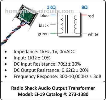
For the two parallel inductors, here we incorporate the primaries of an ordinary radio audio output driver transformers and the series inductor can be any type having the value of around 1000uH.
S4 is the push to ON switch used for triggering the circuit into operation.
S1 is for selecting fast or slow sweep effect option, while S3 is the frequency selector switch, to be selected for fixing the optimal frequency range. P2 sets the final frequency to be delivered across the output.
Adjusting the Frequency Sweep
P1 is for correcting the desired sweep speeds.
The whole circuit operates at 18V, lower voltages upto 12V can also be tried with good results.
A battery pack made from chargeable Ni-Cd cells suits good enough for this ultrasonic weapon application.
The whole unit must be installed inside a plastic enclosure made by fabricating plastic pipes in such away that it resembles a pistol kind of appearance with S4 positioned at the trigger button position.
The piezo must be assembled inside a funnel mouth, and whole assembly to be fixed at the tip of the above fabricated gun barrel.
Circuit Diagram of Sonic Devastator
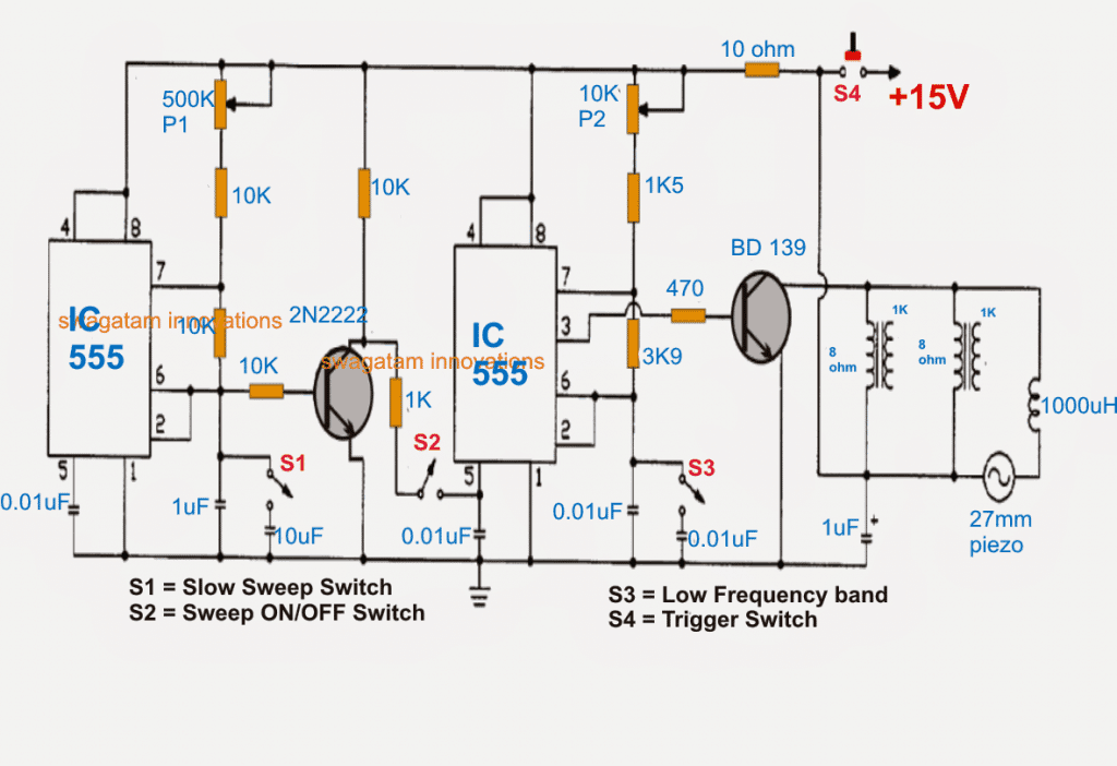
A deeper investigation shows that the sweeping feature of the left side IC 555 via the 2N2222 transistor can be achieved only when the 2N2222 is configured like an emitter follower, as shown in the following modified diagram.
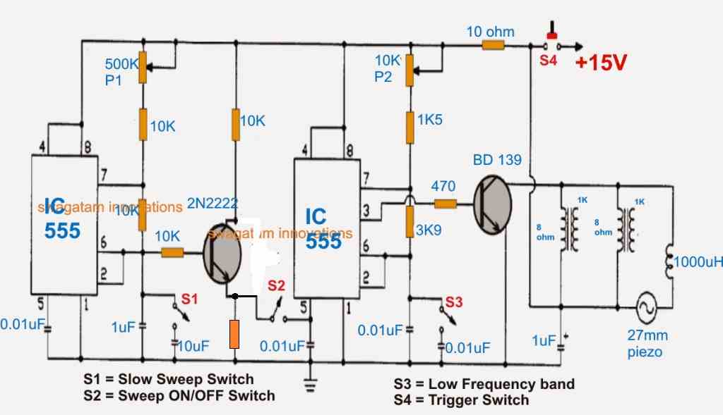
The triangle waves from pin6/2 of the left side will generate a modulating triangle wave, which will amplified by the 2N2222 to feed the pin#5 of the right side 555 and this will generate the intended sharp sweeping ON OFF switching sound on the piezo transducer.
Parts List
Resistors 1/4 watt 5% CFR
- 10k = 4
- 10 Ohm = 1
- 1k5 = 1
- 3.9k = 1
- 470 ohms = 1
- 1k = 1 (at the emitter of 2N2222)
- Preset 500k = 1
- Preset 10k = 1
Capacitors
- 0.01uF = 4 (ceramic disc)
- 1uF/25V = 2 (electrolytic)
- 10uF/25V = 1 (electrolytic)
Transistors
- 2N2222 = 1
- BD139 or TIP31 = 1
IC 555 = 2
Audio Output Transformer = 1 or 2
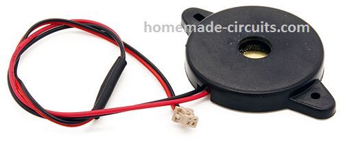
Piezo Transducer = 1 (Assembled inside plastic enclosure)
Inductor = 1000uH
Note: The audio transformers can be completely eliminated if the piezo and the inductor are configured in parallel, between the collector of BD139 and the positive line.
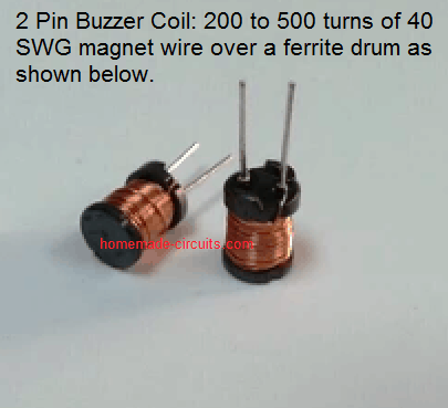
The inductor can be any buzzer coil, and the piezo can be a 27mm piezo assembled inside a plastic enclosure.
Transducer Driver Coil Details
How to Make a Long Distance USW
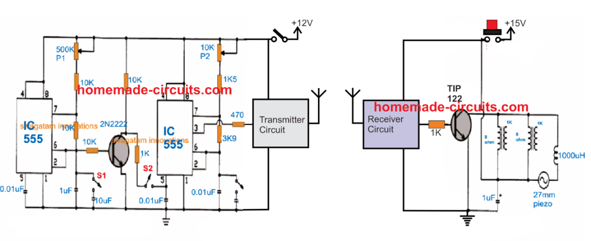
The above design could be effectively used for remote long distance control by configuring it with a pair of RF FM transmitter and receiver circuit as shown below:


Questions & Answers
NICE! Was looking for something like this! Does the shape of the outlet tube have an affect on the sound output? I know from my Radar days in the military that the shapes of the tubes are critical. I assume not so much here?
Thanks JC,
Yes, the radiator shape is indeed crucial here, to be precise the piezo element needs to be mounted inside a conical mouthpiece for effective radiation towards the intruder and for keeping the noise away from the user.
It's great to have a military personnel with me…honored:)
JC, I WILL LIKE U TO SHARE IDEAS WITH US ABOUT SELF DEFENCE TOOLS THAT WILL BE LEGAL TO CARRY AROUND OR KEEP AT HOME IN THIS UNSAVE WORLD.THANKS. OYEKA : 12oyeka@gmail.com
good day sir!!!
may I ask?
1. Where is the piezo here? What will I tell the counter if I buy the piezo like that in the circuit?
2. On the far right side of the circuit, is that a transformers in parallel or just a coil? which is 8 ohms, the primary or the secondary? what are the specifications? (in case its a transformer) how many volts is the primary? the secondary? how many amps?how many watts?
3. Can I replace the transistors with bc547? just in case there is no transistor like that in our place…
4. The inductor is 1000 micro Henrys right?
Good day achilles,
1. The circle situated near the inductors and labelled #26 is the piezo transducer, you can ask for a 27mm 2 point piezo from the shopkeeper.
2. Those are small audio transformers whose secondary sides are only used in the design. You can replace them with any identical high value inductance coil
3. you can use any similar npn general purpose transistor in place of BC547
….yes the series inductor with the piezo is rated 1000 microH
Very new to circuits but I'm getting it, sort of. What specific inductor do I need?
it's a piezo buzzer inductor….or 1000 turns of 36SWG wire wound over a ferrite core
Thank you
I am having no trouble finding the 200MH inductors and the 100MH inductors. There are so many. Which one do I choose?
make sure they are capable of handling upto 500mA current
thanks a lot sir!! you help me a lot to understand the circuit!
I have another question.
1. In your answer in #2, does that mean I'll buy an audio transformer with 8 ohms secondary side, and any resistance on the primary. Or does it need to be 1k ohm?
2. And I can use BC547!?
you can buy an ordinary audio transformer and use its output winding (speaker side) with the above circuit….the winding which has higher number of turns.
BC547 can be used in place of 2907 but for the output transistor you will have to employ a power transistor such as D313, D1315 or TIP31, TIP122 etc
Can I replace audio transformers with inductors? and if yes, what value?
can you give me a specific identity for piezo?
yes identically rated separate inductors will also work in place of audio trafos….piezo could be a 27mm 2-contact piezo element, see example in this article
https://www.homemade-circuits.com/2011/12/how-to-make-simple-piezo-buzzer-circuit.html
what are the values of inductors?
i'm not very sure, i guess it could be around 200mH
Hi sir! good Morning…
can i use any piezo transducer? like what I got in a calculator with beeping sound… thanks!
Hi achilles,
a 27mm piezo will work the best, you can see the example here:
https://www.homemade-circuits.com/2012/04/understanding-and-using-piezo.html
Can I use a 12v piezo buzzer which looks a lot like encased in black circle thing?!
how many volts and amps is the audio transformer? cause that's what the salesgirl keep asking me!!! thanks!!! 🙂
buzzer will not work here, you will need to connect only the piezo element without in associated circuit.
ask for 27mm piezo element
I opened the piezo buzzer this morning and found no circuit just a 12v piezo transducer…By the way it doesn't sound like "buzzing" but like a "tweeeeeet" ing soung…can I use it? thank a lot!!!
the piezo which am referring to should look like this:
4.bp.blogspot.com/-MlUEEIZ2MDw/T5zHauzOS1I/AAAAAAAABNE/IsnTWGcUfkE/s1600/piezo+transducer+element.png
no other types would probably work
And how about the audio transformer rating? thanks
you make one by winding 8 primary and 1000 secondary over any E type ferrite bobbin/core assembly
wire should be 33 SWG or 0.2mm
Sorry for disturbing you again..
Can I use 3-point piezo?
What I mean in audio transformer is the voltage and current..
Thanks…
yes can be used.
how will I connect the pins?
use only the outer and inner areas, leave the central small area, see example below:
https://www.homemade-circuits.com/2012/04/simplest-piezo-driver-circuit-explained.html
you will then need stick the piezo on a plastic base
Hi the pn2907 is only pnp why in the schematics is npn?
yes thanks, it should be actually 2N2222…
HI there,
I've got all the components except the D40D5 transistor as I can't find it.. Can you please recommend a transistor to use in its place? Thanks!
Hi …the transistor is not critical, you can try any suitable 2 to 5 amp NPN transistor such as BD139, TIP31, D1351, D880 etc
Also, would the MJE182 be a good replacement for the D40D5 transistor? Thanks again.
yes it will also do…
Hi again, sorry to bother you.
I've wired up my circuit but it doesn't function, I suspect the problem to be in the way the potentiometers are wired up..
Just wondering how did you wire them up?
Thank you for your help.
Hi, the potentiometers are correctly positioned and varying them will produce the specified outputs.
What kind of sound are you getting presently?
keep S2 disconnected initially and check the response, if there's no sound would indicate a certain fault in the connections.
Sorry I mean with the potentiometer on the diagram, what would it look like physically? I think I may have incorrectly wired it up hence why I am not getting any sound.
I currently have on the 500k potentiometer the 10k resistor linked to the far right terminal on the potentiometer and then the other 2 connections linked to the far left terminal and then have soldered a wire linking the far left terminal and middle terminal together, is that how it should be connected? I have all the components on a bread board and I have a feeling that this is where I've made fault.
Thank you again.
left or right pot terminal orientations are not important….short the center lead of the pot with either the left or the right terminal…this joint together becomes one lead of the pot…while the other free lead becomes the other lead of the pot.
now simply connect one to the positive line and the other to the 10k resistor.
the joined leads of the pot can go to the positive line or to the 10k that's not critical…because pots don't have polarity.
Thanks mate! Got it working in the end, I disassembled it and rebuilt it again and managed to get it working.. must have missed something along the way. Thanks!
That's great mate, congrats!!
What about replacing the output transistor with a 'N' channel MOSFet. What would be the amplitde across 'CE' of outut?
replacing with a mosfet will not improve anything except the cost which may go higher. Th amplitude would be equal to the supply voltage.
The sweep configurations look OK to me, can't figure out the issue, try a diode instead of the 1K resistor between the collector of the transistor and S2…cathode to the collector and anode to S2……check the response after doing this.
Hii, Will this circuit work with 35Khz oscillator?
Thanks,
How functional is this? I wouldn't think that something this small would be more than annoying… Very cool though!
thanks, yes may be it won't cause too much trouble for the intruder but it might certainly help to attract a few folks even from some distance away…
Hi, out of curiosity, what upgrades would you suggest to increase its effective range? I'm talking here about 300m.