The touch alarm circuit senses the mains hum signal from an intruder's body and raises the alarm sound. This happens whenever an intruder touches a potential element set as the sensor, such as the door knob, or any object that needs to be protected.
If the circuit is linked with the door knob, the circuit stays in the standby condition, regardless of any stray disturbance in the air. As soon as an intruder touches the door know, the circuits activates and raises the alarm.
This write-up describes a few alarm systems which employ principles that categorized them as abandoned but not exclusive. Moreover, real-world circuits that comprise type numbers and values are shared. Electronic hobbyists who wish to construct these circuits can do so with just a little effort.
Main Advantage
The main advantage of this touch alarm circuit is that, it will detect only the genuine 50 Hz or 60 Hz hum from the human touch, and will ignore all other types stray electrical disturbances. This means, the circuit working is foolproof, and cannot be triggered with atmospheric electrical interference or even thunder lightening.
There are many trivial circuits available online which show a touch alarm built using a couple of transistor, but these concepts and completely unreliable. These transistorized systems can be easily triggered through stray electrical noise or interference, causing false triggering of the alarm.
Moreover, these ordinary transistor based circuits has to be installed right on the spot of the detection, whereas the proposed circuit can be installed far away at a distance, with only the touch sensor terminated through a cable and installed on the detection area.
Mains Hum Sensor
Firstly, we will observe the touch alarm circuit that recognizes the “mains hum” which occurs when a metal object is touched by somebody.
The transducer can be anything from a cabinet door with valuables inside, or the handle of the door in a room.
Modifying the circuit to fit in a huge alarm system is relatively easy albeit it is defined here as independently operational.
Figure 1 shows a block diagram that depicts how the unit operates.
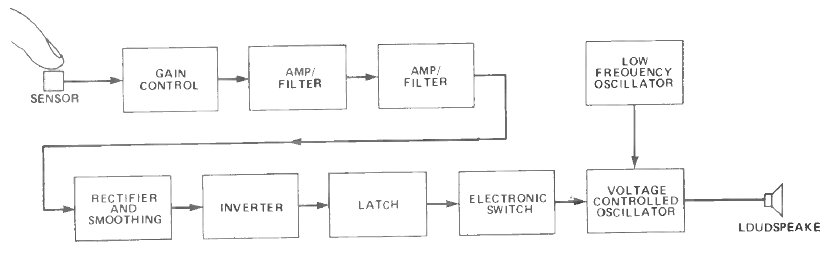
In almost all the buildings, where mains wiring exists, the “mains hum” is sensed by any component that is made of a conducting material.
The human body is included because it can capably detect a hum signal due to its substantial size.
In the touch detector circuit, the metal sensor affixed at the input must be little and attached to the remainder of the component using a short wire that is 300 to 500 mm in length, for longer connections use an appropriately shielded wire.
The sensor flows into a gain control, which is a standard volume regulator with a variable attenuator that can be controlled so that the typical atmospheric stray signal from the sensor does not trigger the alarm.
If the sensor is touched by someone, the reasonably huge signal detected by their body is transferred into the sensor, thus resulting in a powerful input signal that triggers the unit.
Amplification
When the system is switched on based on the condition it is being used, the input signal level will differ.
Two stages of amplification which trail the sensor and a strong level of gain are necessary to cater to the diverse input level, which is not that strong.
A capacitor in each of the amplifier functions as a lowpass filter. Moreover, strong high-frequency feedback is not required as the input signal is the vital mains frequency at 50 Hz with stable harmonics at a couple of hundred Hertz.
The risk of false triggers due to the detection of radio frequency signals can be alleviated by constricting higher frequencies.
Rectifier – Latch
The following section rectifies and smooths the amplified signal so that a positive DC voltage is achieved.
When the system is on stand-by mode, the received signal is too weak because of the voltage drop across the diodes in the bridge rectifiers. Often, there would not be any signal at all.
Nevertheless, when the unit is triggered, an even more powerful output signal is generated, and the DC voltage climbs to a considerable level.
This signal is employed to start an inverter stage which provides some amplification just because a low-impedance output signal of larger magnitude is created.
The generated signal operates the input of a latch circuit and consequently, an electronic switch is triggered.
The switch links power to an alarm generator circuit that is governed by a voltage-controlled oscillator (VCO) to power up the loudspeaker and a low-frequency oscillator to control the frequency of the VCO.
The latter generates a sawtooth output signal which provides control so that the output pitch arches to the top until its peak level and plummets to the minimum pitch before ascending again.
This cyclic process warrants an extremely efficient alarm signal. As the latch is included in the unit, the alarm will constantly blare even when the component is not triggered by the sensor anymore.
Hum Detector Circuit
Figure 2 describes the complete touch alarm circuit schematic of the Mains body Hum Sensor Alarm.
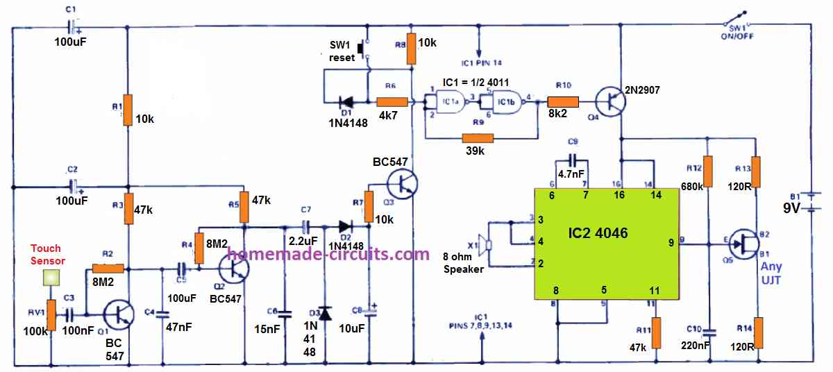
The sensor connects into preset gain control RV1 and afterwards the signal is analysed by two common emitter amplifiers which are constructed around Q1 and Q2. Capacitors C4 and C6 take care of the filtering activity.
Moreover, capacitors C3 and C5 may display low-value characteristics since low frequencies are utilized in this process.
Considering Q1 and Q2 are worked at extremely small collector current values, they possess larger input impedance than the usual common-emitter amplifiers. As a result, the coupling capacitors are sufficient for practical use.
While diodes D2 and D3 rectify the output from Q2, capacitor C8 smoothens it. In case an adequately large potential is produced, it forces Q3 to conduct so that its collector current becomes low.
Two NAND gates, IC1a and IC1b of CMOS 4011BE quad 2-input NAND device make up the latch circuit.
However, these two gates are linked in a series connection and function as typical inverters.
The positive return state to trigger the latching operation is supplied by R9. Diode D1 makes sure transistor Q3 can attract the input of the latch low but would fail to push it to the high state.
A workaround is possible by employing reset switch SW1 which is linked to the opposite side of D1.
Once the output of the latch is activated to the low-state, it turns on Q4 which eventually delivers power to the alarm circuit.
This depends on IC2, which is a CMOS 4046BE phase-locked loop but in this operation, the VCO segment and a single-phase comparator are used. The latter functions as an inverter stage that provides the two-phase output signal.
The output signal operates ceramic resonator X1 compared to a standard coil loudspeaker.
The operator produces a shrieking output from the low-drive current that is offered from IC2 and is considerably noisier than expected.
If required, the output from pin 2 of IC2 can be enhanced and channelled to a typical loudspeaker.
The sawtooth modulation signal is produced by a standard unijunction relaxation oscillator that derives from Q5.
Adjustment
Setting up the touch alarm circuit is not complicated. Begin with RV1 altered for the lowest sensitivity and then increase gradually until the alarm is triggered.
Next, retreat a little from this setting and try resetting the alarm. If you find the alarm activating again, turn RV1 a little in reverse more and restart the unit once again through switch SW1.
Simple Touch Alarm using a single 4011 IC
This is a sensitive and touch detector alarm circuit that mainly relies on a simple CMOS 4011 circuit.
The schematic diagram shown below remains straightforward, and its operation is reliable.
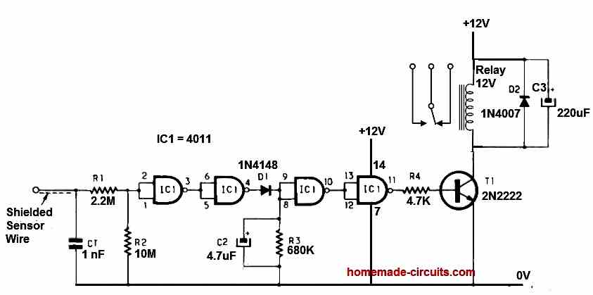
The sensor is placed near the lock of the door that needs protection, using an appropriate length of shielded cable (maximum 30 cm).
If an unwelcome person tries to pick or force the lock with a metallic tool, the signals generated by their body are transmitted through the metal parts and captured by gates 1 and 2 of the 4011 circuit.
These signals are then amplified and detected by diode D1, subsequently setting gates 3 and 4 to either level 0 or 1, depending on whether the detection is active or not. When the 4th gate of the 4011 is at level 0, T1 (2N2222) conducts and powers RL1, a small relay plugged into a 16-pin socket.
This relay switching triggers the connected alarm siren.
However, in its current form, the circuit only provides information that is difficult to process, as it is too transient, especially if the intruder hesitates during the attempted break-in.
To address this issue, a "temporary memory" is introduced in the form of a delay in resetting the circuit. This is the role of C2, whose value can range from 2.2 μF to 4.7 μF (tantalum capacitor is desirable but not mandatory). Each person can adjust the value of C2 according to their own criteria.
As a result, even if the intruder briefly touches the lock, they unknowingly validate information that is stored for 1 to 3 seconds (depending on the value of C2).


Questions & Answers
Hi dear Mr Swagatam
I have made a vco circuit using 4046be.
Every thing is ok . Vcc is 5 volts and the frequency is 250 Hz.
But the problem is that when i use the output frequency to run a npn transistor or even a led frequency changes and 2.6 v out put falls to 1 volt .
Hello Ehsan, it may be due to very low current in the signal. Please use a Darlington transistor, and use 100k resistor at the base and check the results