IC 555 adjustable timer explained here can be adjusted from any time delay 1 second to 3 hours for operating any load through a relay control
The produced time delay is fully adjustable and the user has the freedom to set the time period as desired.
There are many ways of making simple timer circuits using different ICs and discrete components; here I have explained one such circuit using the ubiquitous IC 555.
The IC 555 is a pretty common electronic part among the electronic enthusiasts and is also very popular due to the involved simple configurations and low component count.
The two popular multivibrator modes of operation that’s associated with this IC are the astable mode, and the monostable mode. Both of these are useful configurations and have plenty of different applications.
Using the IC 555 in Monostable Mode
For the present adjustable IC 555 timer circuit design we incorporate the second mode of operation, which is the monostable mode.
In this mode of operation the IC is configured to receive a trigger externally, so that it’s output changes state, meaning if with reference to the ground if the output of the IC is zero, then it would become positive as soon as the trigger (momentary) is received at its input terminal.
This change in its output is sustained for a certain period if time, depending upon the external time determining components. Normally the time determining components are in the form of a resistor and a capacitor which together determine or fix the time period for which the IC output would hold its “high” position.
By changing either the value of the capacitor or the resistor, the timing can be altered as desired. The above time fixing components are termed as the RC component.
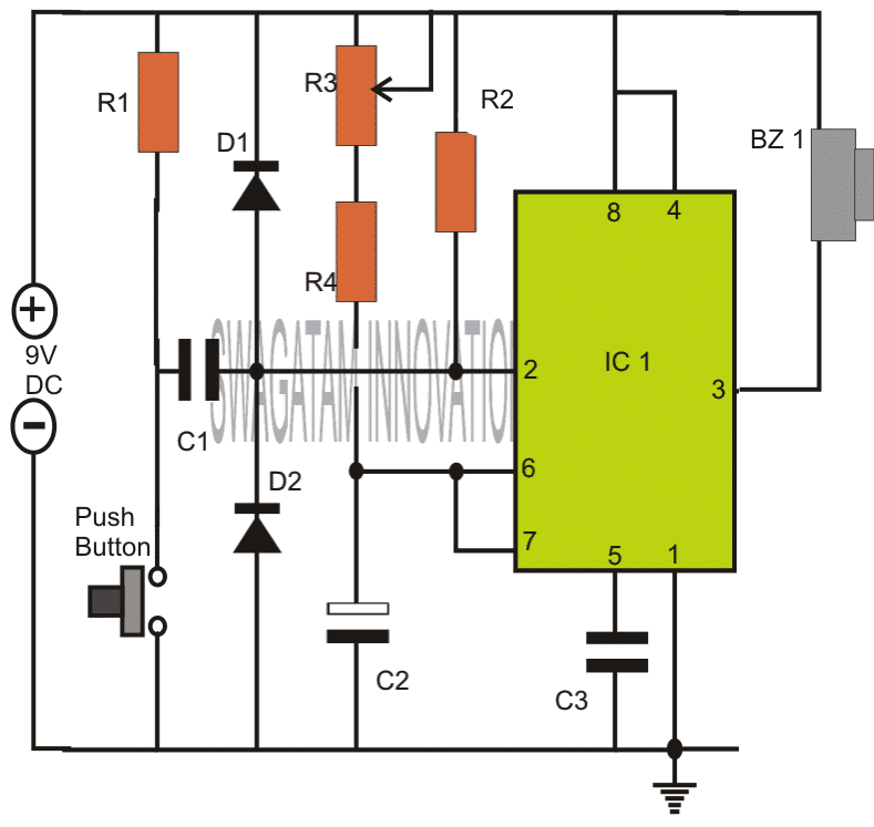
Note: Please connect the buzzer or the load between pin#3 and ground, and not between pin#3 and positive as incorrectly shown in the above diagram.
How the Circuit Functions
The 555 IC timer circuit above shows a very straightforward design where the IC 555 forms the central controlling part of the circuit. As discussed in the above section, the IC is in its standard monostable mode.
Pin #2 receives the external timing trigger from a push-to-ON switch. Once this switch is pushed, the circuit pulls its output to a positive potential and holds it until the predetermined time delay lapses.
The entire circuit can be built over a small piece of general PCB and housed inside a neat looking plastic enclosure along with the battery.
The output may be ideally connected to a buzzer for receiving the warning alarm after the set time lapses.
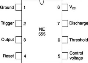
Parts List
- R1, R4 = 4K7,
- R2 = 10K,
- R3 = 1M pot,
- C1 = 0.47uF,
- C2 = 1000uF/25V,
- C3 = 0.01uF,
- IC1 = 555,
- Bz1 = Piezo Buzzer,
Push Button = push to ON switch circuit design requested by Mr.Bourgeoisie:
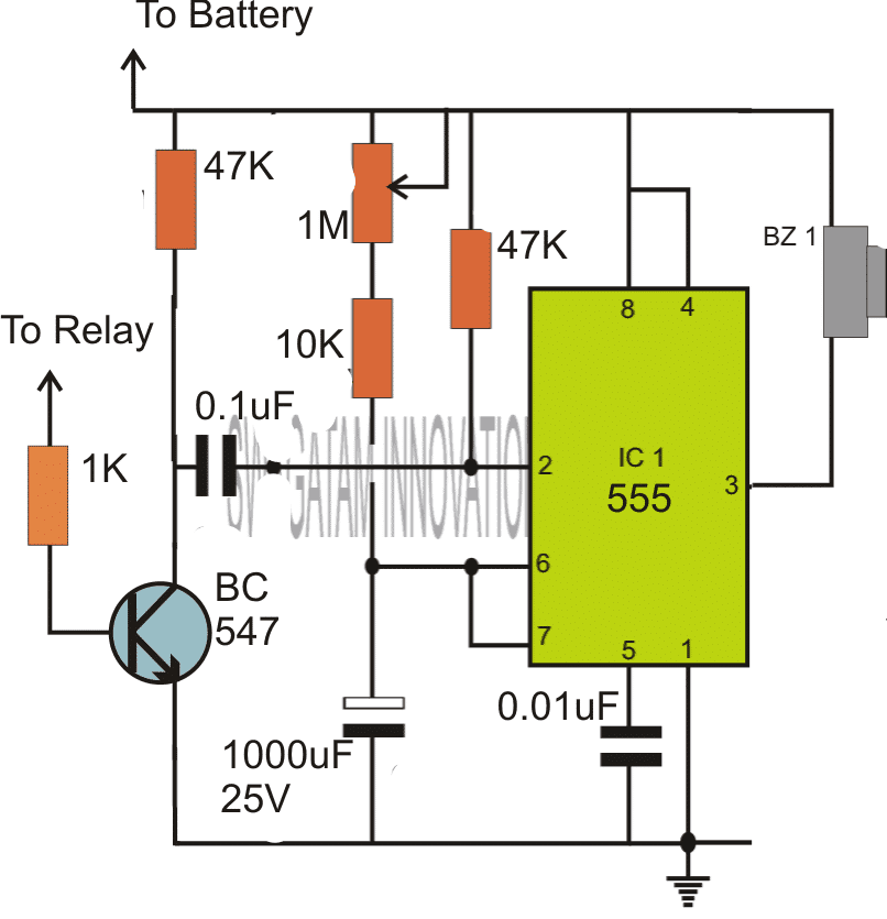
Please connect the buzzer or the load between pin#3 and ground, and not between pin#3 and positive as incorrectly shown in the above diagram.
Timer Circuit with Relay Switching
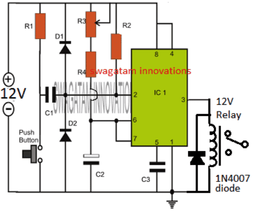
If you are wondering how the above simple timer circuits could be used for triggering a high power load through relay switching, then the following diagram will help you to implement the same by attaching a simple relay stage with the shown designs:
Parts List
All resistors are 1/4 watt 5%
- R1, R4 = 4K7,
- R2 = 10K,
- R3 = 1M pot, Linear
- C1 = 0.47uF Ceramic disc or PPC,
- C2 = 1000uF/25V, Electrolytic
- C3 = 0.01uF, Ceramic Disc
- IC1 = 555,
- Diode = 1N4007
- Relay = 12V/400 Ohm relay,
- Push-button = Any push-to-ON switch
Circuit Operation
In the shown diagram, when power is switched ON, the IC goes into a standby state, and no triggering action is initiated at this moment.
However as soon as the push button pressed, pin#2 is pulled down to ground which instantly triggers the IC in the monostable counting mode, and the relay is activated. The load connected with the relay is thus also activated.
The IC starts counting, and depending on the values of R3/R4, and C2, once the timing period gets elapsed, the IC resets to the previous standby mode deactivating the relay. The relay load also gets deactivated in this situation.
The cycle repeats each time the push button is pressed, enabling the user to achieve the relay triggered timing ON OFF feature in the circuit.
The timing interval can be increased or decreased to a given extent by suitably altering the pot R3 value and/or by modifying the value of C2.
Prototype Images
The above explained 555 adjustable timer circuit was successfully built and tested by Mr. Vee, who is one of the dedicated readers of this blog, and a serious electronic hobbyist.
The circuit was appropriately modified to suit his personal timer application. The modified image can be viewed in the following diagram:
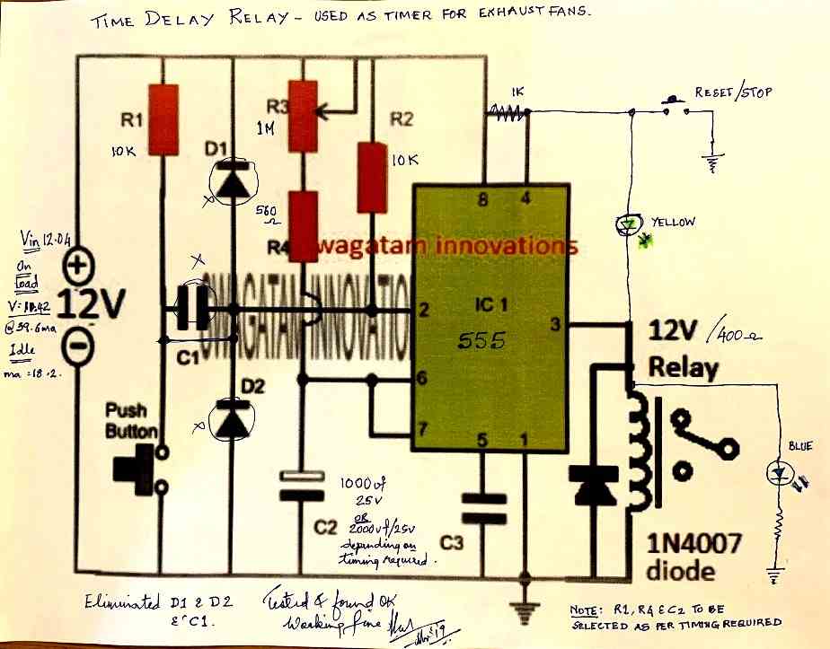
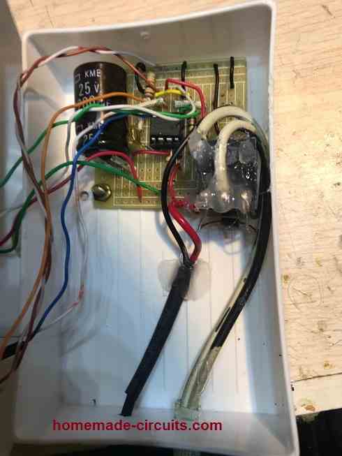
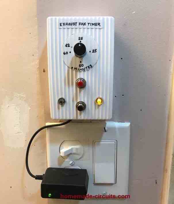
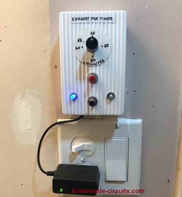
The prototype images of the above timer unit can be witnessed as shown below (built and tested by Mr. Vee):



Questions & Answers
Hi swagatam ,I wanted to construct a circuit which uses a small voltage of less than one volt to control a relay of 12 v.how can I go about?
Hi Ben,
You can try a relay driver circuit as shown here:
https://www.homemade-circuits.com/2012/01/how-to-make-relay-driver-stage-in.html
You can try this circuit:
https://www.homemade-circuits.com/2013/07/simple-triac-timer-circuit.html
You will have to remove D2 and replace the triac with a transistor/relay driver stage, after that the variable may be set for achieving the required timing.
Hello sir, I have formed this circuit in multisim 12.o. i have the muscle stimulator as the other circuit. can this muscle stimulator be the trigger?? if i put these two circuits on 1 board in multisim, will the result show??
Hello sir. I just wanna ask if i put this circuit and a muscle stimulator circuit as the trigger in multisim 12.0, will the result show, like the buzzer would buzz? or it should be done physically to know the results??
Hello Jaejjii,
I don't think the simulator would be able to simulate your muscle simulator response along with the above circuit….so I think you should test the configuration practically.
Hlo sir
Kindly help me. I want to make a (0 sec-1 min) adjustable 555timer circuit.
Without using push button to trigger the circuit and a relay is connected to operate heavy load.
Working—As soon as circuit get power input it switch on the relay for the adjusted interval and then automatically cut off the relay when delay time is finished.
Waiting for reply
Thanks
Hello Avi you can try the following concept:
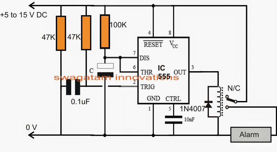
You will have to adjust the values of the 100k and “C” to get the required delay for the relay
hello sir…fist of all thank u for running such a nice blog…sir i want to make a three light running chaser to be worked on ac lights…and want to keep interval switching time 1 minute…pls pls help me sir….thanxx
Helo Nitin,
I have explained it in your previous comment with a link….for 1 minute interval you just need to adjust the pots carefully for the required timing.
You can try the second circuit given in the above article, do the following modifications in it:
Remove the buzzer, and put a relay across pin3 and ground.
Remove the transistor and replace the position with a 0.22uF capacitor, also put a 1M resistor in parallel with the above cap.
The timing can be set by adjusting the shown preset.
Whenever power is switched ON, the relay will hold and then deactivate after the delay period has lapsed.
The reay contacts may be wired up with the hair dryer.
Hi Swagatam
Would you please tell me the functions of D1, D2 and R1? I have just blew a 555 without them.
What would be the configuration for a positive triggering signal?
Hi Abu-Hafss,
R1/R2 are for discharging C1 so that it becomes ready for the next input pulse
D1/D2 are not crucial and may be removed, these are for restricting the entry of high frequency disturbance at pin2 and for eliminating false response by the IC.
There's no way you can blow this IC, unless you short circuit the output for too long or reverse the supply polarity…..
You will have to construct it first and then check it as per the given instructions, that's all. If you face problems while troubleshooting I'll help you.
Hi Swagatam
I am really exhausted, I admit, I have failed. Please help me.
I need two monostable 555 timers configured such that:
1) when switched on, ONLY the first timer should be triggered automatically
2) after completing its preset time the 1st timer triggers the 2nd timer
3) after completing its preset time the 2nd timer triggers the 1st timer
4) hence the cycle repeats indefinitely
Just let me know how to connect the pin #2 of both timers.
Hi Abu-Hafss,
I'll do it for for but in return you will have to explain the circuit in your own words, …agreed?
Okay………………
Actually, I had made the circuit; and as per my usual practice I simulated in 2 different softwares. One worked perfectly, but the second one (LTSpice from Linear Technology) did not accepted. And I mostly rely on LTSpice, which I consider to be much accurate.
Here is my circuit
Hi Abu-Hafss,
The trigger inputs are not configured correctly in your circuit according to me, I'll try to update the correct one soon.
Hi Abu-Hafss,
Please refer to the "sequential timer" section in the following pdf link:
http://www.ti.com/lit/ds/slfs022h/slfs022h.pdf
Hi Swagatam
The link shows monostable timer with manual triggering whereas, I was talking about automatic triggering at power-up.
If for example we have 3 sequential timers:
a) Only the first timer should start at power-on.
b) The first timer should trigger the second.
c) The second should trigger the third.
d) The third should re-trigger the first one.
My problems is how to restrict the 1st timer to be triggered automatically at power-up?
According to my observations, sometimes 1st timer gets triggered, sometimes 2nd, sometimes 3rd, sometimes all three and some times none.
Hi Abu-Hafss,
Replace the switch "S" with a 1uF capacitor and also connect a 10k resistor across the positive and pin2 of this IC, now the circuit becomes an automatic sequential timer as soon as it's powered up.
The circuit will always start from IC1 when switched ON as per my simulation, just try it.
Good afternoon sir,
Would U kindly mention the value of D1 & D2.
Wheather a 6v relay will work instead of a buzzer?
Inform the caution to be taken for 6v supply instead of 9v d.c.
Thanks …………….
k.kausik
Kaushik, D1, D2 are 1N4148 diodes
6V relay can be used but the supply should be also at 6V
the same circuit can be used for 6V operation also, no changes would be required.
Good evening sir,
Wishing you a hearty thanks for your kind reply…….
A request ;
A search option & "go to top" is needed on your web page……. So many useful circuits …a huge no of posts & comments…..
With regards,
K.Kausik
Thank you Kaushik,
Your suggestion is very good.
If it's possible to include this feature in my blog template, I will make sure it gets implemented soon.
….by the way the search option is already there at the left top of sidebar.
sir, can i use the same circuit above using a 12volts power supply? or do i have to modify some of the parts?
Jomel, 12V can be also used for the same circuit, no changes would be required
Hey Swagatam,
I like ur circuit and i am new to electrical world.
So i want to know that if i have an input of 220 volt ac , what value of resistance i must have to add do that i get output of 9 volt ac
Thanks Vipin,
If you are referring to the above circuit, for a 220V operation you can use a 12V AC/DC adapter for it…..12V would also work for the above circuits.
sir,i'm planning the same circuit above to control a motor of 12v, 8 amps for a certain time duration,i attached a tip3055 transistor in series with a 1M resistor to the output in place of the buzzer, will that work?
Jomel, you will need to do it via a TIP122 transistor.
connect the base of TIP122 to pin3 of the IC via a 1k resistor.
connect the emitter of TIP122 to the base of TIP3055
connect the emitter of TIP3055 to ground.
join the collector of both transistors and connect it to the negative of the motor, and connect the positive of the motor to positive of the supply.
Hi Swagatam
TIP122 is a darlington pair, so shouldn't it be replaced with TIP31?
Otherwise, what would this configuration be called i.e. 3 transistors connected in series with common collector?
Hi Abu-Hafss,
Here we are looking for a guaranteed and an optimal switching conditions for the 2N3055 since the source current is very low in mA.
Therefore a Darlington is a better choice since it would ensure the full dose of current for the 2N3055 producing an optimal switch-ON for the load
OK,thank you sir,i will try and see what will happen
Sir,may i ask what is the reason behind the additional transistor tip122?
Jomel, for 8amp collector load, the base of 2N3055 would require around 200mA current, TIP122 is used for optimally satisfying this amount of current to the base of 2N3055
Good morning sir,
My android mob. is the only way to connect with Net. It's quite tough to search any particular ckt. Plz. Help!!
I need to convert 12v a.c to 12v d.c
A tr. manufacturer told that when a bridge rectifier is added with the out put of 12v d.c it increases the voltage upto 3v. Is it true? Then what should I do….
1)A tr. of 9v d.c out put…
2)any ckt. that provides 12v a.c to 12v d.c using a tr.
Please guide.
With regards, k.kausik
Hi Kaushik,
yes that's right. in fact with a filter cap it could rise upto 16V
you can use a 7812 IC for restricting the voltage to 12V or add 4 to 5 rectifier diodes in series with the positive for the same.
the diodes could 1N4007 or 1N5402 depending upon the output current specs
I want to make a circuit which work's like I have 9 25 watt clf bulbs and I want to do that when I switch off the first CLF then after each 5 minutes the remaining light would switch off regularly like each should go off after 5 minutes of other means that in 45 minutes all 9 lights go off respectively.So in this case would the last circuit among the drawing's will work or not.Please help me ?
I'll try to design it soon and post it in this blog.
Hello Swagatam i wanna ON my Banner Light with 555 Timer IC for particular hours like 6-8 Hours and then i wanna off it automatically. Is it possible? Please help me regarding this. it will be helpful for me.
Hello Nipun, a 555 IC circuit may not be suitable for acquiring such long delays due to its inefficiency, a 4060 IC is recommended for this as explained in the following article:
https://www.homemade-circuits.com/2013/07/simple-triac-timer-circuit.html
try the second one for your application
how to increase time duration of this timer? like 4 hours timer
by increasing the values of R3/C2
Hello.
If I changed the voltage to 15V, will the values of other components change? If yes, then what will be their new values?
Hello, nothing will need to be changed for 15V, however at 15V the IC can get a bit warm so it's not recommended.
Hello Swagatam, I would like to know if an IRS2453 can be driven by an external oscilator, like UC3845. I want to use this circuit to drive a H bridge in a welding inverter.
Hello Alexandru, According to me it does not include this feature, it can be programmed only through the specified Rt/Ct network….
hello sir,
i want to make a bathroom light timer switch with IC555, but i want to add a warning alarm sound before the lights goes off when the time limit is reached, can you help me?
Hello Enrico, I can certainly help you, please let me know what type of buzzer and lamp do you intend to use in this application.
buzzer is DC type and lamp is fluorescent type…what im trying to do is to make it give a warning sound(somewhere about 15 seconds) before the timer switch the lamp off.
the timer is adjustable from 1-10 minutes
OK I'll try to post it soon…
I am new to electronics but I thing this circuit is ideal to start with. I wish to use the cct on a device. The idea is to set on the buzzer after I set the time sort of a reminder. Does this cct help. Let say I want thw buzzer to sound at 8.00 am, noon and 6.00pm is it possible please.
No it won't be possible with this circuit, you will need a 4060 based timer circuit
I tried to find a cct but I not sure if it works properly do you have available on you site
you can try the following circuity:
https://www.homemade-circuits.com/2012/01/how-to-make-simple-versatile-timer.html
remove D1, otherwise the time delays will not repeat.
The timer will produce OFF/ON delays with equal intervals depending on the values of the P1 and C1.
i want to make a simple timer for a 3hp 220v ac motor to make it on for 30 min and off for 15 min , what circuit should i make?
i want to make a simple timer for a 3hp 220v ac motor to make it on for 30 min and off for 15 min , what circuit should i make?
you can try the following circuit:
https://www.homemade-circuits.com/2012/04/how-to-make-simple-programmable-timer.html
Thanks a lot ,I will try it 🙂
Hi Swagatam. I building your simple CDI circuit. which is fine for a single cylinder motorcycle motor. However. I intend to use it on a 2 cylinder V motor. Most of these motors have 2 pick ups, but the motorcycle I have, has only one pick up. This means that it fires on the first cylinder ,but I need to time delay for the second cylinder also using a second CDI. A milli second adjustment would be needed to get the required TDC firing point. Can I configure the above circuit from the pic up for the pulse. Can you help
Hi John, are you sure a manual, fixed delay setting would do the job? I don't recommend it…I think it would be much better if you installed a second pick-up coil and a separate CDI for triggering the second engine.
By the way if you think the manual option would be OK, then you could try the following design instead
https://www.homemade-circuits.com/2013/02/make-this-simple-delay-on-circuit.html
adjust R2/C2 for the required delay, and remove the relay….the trigger could be extracted from the colector of T2
Hi John
Please inform the name/model of your motorcycle.
Hi Swagatam.
Thanks for the time delay switching circuit.Much appreciated. Tomorrow I'm starting trials with the CDI. if I get the spark at both positions at their required TDC points, the timer won't be necessary, but if I'm correct, the time delay will be needed for the second cylinder in the V 2 cyliner motor. As it must fire before the pic up flywheel can do another revolution. Meaning 2 cdi's, one with the time delay the other without. I'll keep you posted.
Just a note. I am also going to add your advance /retard circuit, as well as the the auto select for the advance/retard. To make an intelligent CDI giving optimum performance.
You are most welcome John! If your theory is correct then my referred circuit should work with perfect results, however how would you implement it for the proposed function? that appears to be a bit puzzling? Let me know if you need any help regarding this. Wish you all the best!
The bike is a Despirado 400. Not sure but I think the model is around a 98. I can't find A wiring circuit anywhere on the net.Ive tried to buy a new CDI but every place I've got one from are Duds. So I'm building on. The big problem is, it has only one pick up. with the firing at 180 degrees from TDC of the first cylinder to the firing of the second cylinder.Thats about 0.0588 of the second time out needed.This is at Idle speed of 1000 rpm. Take that to 8000 rpm at full revs. I still need the advance and retard. with the time out changing as well to about 0.0167 of a second. The XV4002NT Smart CDI is the correct CDI. I cant afford the new price at R14000.00 The value of the bike is only R35000.00 I've been ripped of twice trying to buy. So if anybody has one. I can afford R2000.00 and only after it's fitted and the bike is running.
thanks John, I can design the circuit as per your above specification which will spark the two engines at a given predetermined rate, and that won't cost you more than Rs.800/-….the design might include two identical CDI sets and a sequential timer circuit
I need to make a simple timer circuit that only turns on an led for an adjustable amount of time between 10-60sec then turns off for 5-20min. ther will be a sensor or switch used to cycle the circuit on/off. When the switch is closed and the power is restored to the timer circuit, the led will need to be powered on then count down to the off state. This will need to either run on a 3 or 6v battery source. I am not sure if This should be a 555 or 556 timer or 4060 as in your other programmable timer circuit. The accuracy of the timer is not critical but it needs to be reliable. I do have a 556 timer already. Your help would be appreciated. Thank you.
Hello, I need help designing a circuit that's adjustable and only turns on an led for 10-60sec and turns off for 5-20min. It will run on 3v or 6v battery and I will use a sensor or switch to power up the circuit. When the circuit gets powered up, the beginning state of the led must be "on" and then begin the timer function to turn "off" then remain off until the next timer is complete then it repeats. The accuracy is not critical but should be fairly accurate and reliable. I though of using a 556 timer which is a double 555 timer or possible using 4060's. Thank you for your help.
you can try using a couple of 555 iCs or through a couple IC 4060 as shown in the following article
https://www.homemade-circuits.com/2012/04/how-to-make-simple-programmable-timer.html
for getting an initial LED ON connect it across the N/C of the relay and not N/O
if you don't want the relay, the top BC547 can be replaced with a PNP, and the LeD connected across its collector and ground.
Thank you for your reply. I will base my circuit on the 2 4060 design in the link you provided. What is the equivilant PNP transistor to use since I will not be using a relay? Also, can I use 100k micro trim pots to adjust timers? My local Radio Shack has limited supply of components, the .1uF capacitor is a ceramic disc and the 1uF is a tantalum, will these work ok? I will be building this circuit as soon as i can locate all the components, I really appreciate your expertise. Is there any chance you can draw a schematic for me with with PNP transistor rather than relay and eliminate the red/green status LED's?
the 1uF should be a non-polar capacitor so tantalum will not do since it could be a polarized cap.
the PNP spec will depend on the load, if it's below 200mA, a 2N2907 will do, if it's below 50mA, then a BC557 will do.
make sure to put a series limiting resistor with your LED
your 0.1uF is OK
hi sir , i am disturbing you again with my small doubted and mistakes, from your suggestion i got idea regarding the led drive circuit and it working fine,
and now need a timer function, when i switch on a device i need delay to operate protect my device,only after few second i want to switch on the device , please give me suggestion
Thanks Asainar,
you can use the following concept for your requirement:
https://www.homemade-circuits.com/2013/02/make-this-simple-delay-on-circuit.html
you can include the relay for controlling the LED delay time or simply remove the relay and connect the LED with the collector of the PNP transistor, but in that case make sure that the PNP is rated appropriately to handle the LeD current.
Hello Swagatam
Very generous of you to offer your expertise to us experimenters. Perhaps you can help me with a design ?
I need a circuit that once triggered, will do two things in succession. First, after a set period of approx 2 minutes it must output a continuous series of high-low pulses of about 2 second period with a 50% duty cycle, though that is not critical. Then about 30 seconds later it must output a permanently high state and remain latched. Perhaps this could be done with two 555’s or a 556 ?
Your help is greatly appreciated. Regards, Paul ZS2OE
Thank you Paul,
You can check out the following diagram:
There are a few resistors and capacitors around the two IC 555 which will need to be calculated for getting the required 2 second frequency and the 30 second latch period.
Thank you very much for your trouble Swagatam – this looks like it will do the trick.
No Problem!
Please for astable timer, I want to make a 2secs delay between on and off
Please calculate using the software which is given in this website!
I have calculated and got time for on and off repeatedly but I need a delay in between the on and off, I didn’t get that
Try a 555 PWM circuit.
please how will the 555 pwm circuit work sir
you can change the pot position to vary the ON and OFF time proportionately
Please any circuit diagram for this, and how to combine it for 5secs on and off and 2 secs delay in-between. Thanks
Sorry I didn’t understand what you mean by 5secs on and off and 2 secs delay in-between?
I made an astable 555 timer at 5secs on and off, but I need 2secs delay in between on and off.
Do you mean 5 seconds ON and 7 seconds OFF?
Timer Circuit with Relay Switching
dear sir i want slight modification of last circuit.i want in this circuit when the push button is CONTINUOUSLY keep pressed the relay to be activated for desired time and then deactivate. only the cycle repeats if push button is released. i mean weather the push button is momentarily pushed or continuously keep pushing the relay to be activate once and deactivate. the circuit is im using for coin collecting box in a buddhist statue in our village SRI LANKA. when some one put coin to the box the micro switch is operating a flash bulb and some bajan geeth for some second (Audio). im facing problem while coin is getting stuck on the plate attached to micro switch the bhajan geeth playing continuously with continuously flashing the bulb. to over come this i want to modify above circuit request instructions sir.
yes, the relay will switch OFF after the predetermined time even if the push remains pressed…you can use the shown design as given, no chnages are required
C1 may need to be increased to 0.47uF for better response
Sorry your email did not go through
Regarding your adjustable timer circuit with 555 IC
My hot water heater is 75-100 ft from my HW faucet in the bedroom. There is a recirculating pump that can keep hot water hot flowing throughout the day. There was a 24 hour timer in the system with several on/off periods. Many years ago I rewired and put in an on/off push button to control hot water pump. I installed a chip/rectifier that controls the 110v on the pump using 12v. I wired the 12v DC to the bathroom. Works great except much of the time we forget to shut off recirculating pump once we turned it on. I am sure I can use your adjustable timer circuit
I need clarification how to install. I have a push button switch to open/close the 12v signal in the bathroom. I add timer circuit at the pump end in the garage. I have a SRD -12V -SL-C relay plus other proper capacitors, resistors and the 555 chip. Do I install control assembly into the 12V DC side in garage or into the 110V side controlling pump with relay. I am trying not to go up in smoke the first time I install it.
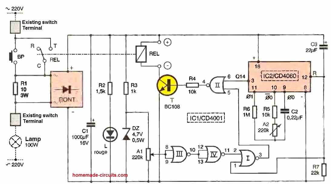
Hi, I guess you are looking for an automatic cyclic timer system instead of a manually switched one, in that case the above concept won’t be suitable since it is a one-shot timer, instead you could build the following design

Hi
I am looking for a circuit that can detect water falling into my washing machine during the intake cycle and switch on my pressure pump through a 12V relay. The pressure pump should be switched off about 1 minute after the water intake cycle has ended. So the pump should be switched on as long as the water is being detected and switched off 1 minute after water flow has ended.
Please help.
You can try this:
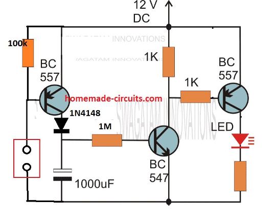
replace the LED/resistor with a relay and wire the pump with the relay contacts.
Hello Mr Swagatam, can you help me with a circuit I’m trying to make?
I have a simple 555 circuit that can generate 10KHz sq pulse around 30mA 7V. How can I integrate your circuit to do a auto power cutoff after 8 mins? I can use a single dual 555 IC pkg and run on a single 9V battery. Is a relay (big and bulky) necessary or can a simple logic gate do the power cutting off?
Thank you for your help.
Hello WK, how do you want to initiate the timer, is it through a manual press switch. You will need a delay ON timer for this, which can be integrated with pin 4 or pin5 of your IC 555 astable for shutting it off
Hello, I want just one switch (press once to on) to turn on both timer and 10KHz oscillator. The timer will cut off all battery power after 8 mins. Press the switch to start all over again as many times.
I might consider a selector switch later to change the different timer duration via resistors (3mins, 5mins and 8mins).
Is this easy to accomplish?
Thank you Swagatam 🙂
Hi, I will try to design it soon for you!
Thanks, but I’m thinking more in line with your 1st circuit with a buzzer. It is 9V operation and has no relay. Can the buzzer output be replaced with something to cut off all power?
You can try this and see if it works, power can be between 5 and 15 V:
Thank you very much. I’ll buy the components and try it out, hopefully by next week.
🙂
No Problem, wish you all the best!
Hello Mr Swagatam, may I know what is the model of the 2 diodes D1 & D2? They are not in the list of components.
Thanks.
Hello WK, those are optional elements, you can use 1N4148 for them
So what function do they serve? Keep C1 voltage constant?
Do you mean that if I don’t put diodes there the circuit will work just fine?
Thanks again Mr Swagatam
🙂
Yes even with without the diodes the circuit will work fine. The circuit was originally designed as a tachometer for measuring pulses from vehicle alternator and the diodes were added to safeguard the IC from alternator voltage spikes.
Hello Mr Swagatam,
A 220v AC voltage stabilizer (with four relays) is connected with my fridge but unfortunately this stabilizer don’t have a timer delay. Please help me to construct a 3 minutes timer circuit for my voltage stabilizer so that my fridge remains off for 03 minutes after power recovery or in case of surge. It will be better if the circuit is drive through 220v AC.
Waiting for your kind help.
Regards
Nisar
Hello Nisar, you can try the concept explained in the following post:
Simple Refrigerator Protector Circuit
Dear brother,
bundle of thanks for your kind help.
Regards
Nisar
You are welcome Nisar!
Hi Swagatam,
In the pop up toaster they use toaster controller PT8A2512NE to pop up the bread after some time (variable). I tried getting the controller in Delhi but was not successful. I was thinking that 555 can be used in place of PT8A2512NE with some modification in the original circuit. Please suggest some reliable circuit with 555.
Hi Ashok, yes it is possible, I will update the finalized diagram soon for you through this comment thread
Thanks will be awaiting the circuit diagram
I have updated the diagrams below:
Original Diagram
Modified IC 555 toaster circuit diagram
Capacitor C1 will need to be experimented for the 30 second timing
Dear Swagatam,
Thanks for the circuit, I assume R2 will be 1M variable resistance. The time required will be 0 to maximum 10mts maximum, because in 10 mts the bread will burn. This I will check experimentally.
Thanks once again
Regards
You are welcome Ashok, yes 1M can be replaced with a pot, but make sure to add a 10k resistor in series otherwise the IC can get damaged while turning the pot towards the positive extreme.
This 1M and the C1 can be experimented for the requred output delay OFF, which can be achieved by using the following software:
https://www.homemade-circuits.com/ic-555-timer-monostable-circuit-calculator-software/
Try the lower option, since the first option requires the C1 to be in Farads.
I will also like to be notified when you post the toaster circuit using 555 timer
Hi Swagatam
I have built a time delay relay using 555 IC with a timing upto about 1 hour, I understand that the 555 has its limits of the RC of upto 1 meg and 2200 cap.
I would like to build a time delay relay from 10 mins to 2 hours in steps of 10 mins to use it with my cell phone charger to avoid over charging my phone as it is recommended to keep your phone charged between 30 & 95% not more to avoid over charging and bulging the battery
I tried making one with the IC 4060 but it’s unstable I don’t know why
Please help & thank you very much
Regards
Vee
Hi Vee,
all cellphones already have an internal over charge cut-off circuitry, so even if you connect the charger permanently or forever with your mobile phone that still won’t damage anything in the phone.
Regarding the timer, since the 555 timing capacitor is the main component that determines the timing output of the IC, you can put several capacitors of incrementing values, and use a selector switch to toggle across the capacitors, so that it allows you to get the desired timing in steps.
Ic 4060 is a highly stable timer IC, since it is a CMOS based IC…it is much more stable and accurate than a IC 555 timer. You can you recheck your circuit to ensure everything is connected properly.
Hi Swagatam
Regarding the mobile internal cutoff for charging circuit, I understand it is supposed to be there, but I’ve read many articles regarding this and it is recommended to keep the charge between 30 & 95% and Ive practically seen this helps as I do this and have never replaced my iPhone battery in years. I’m a bit confused now
Anyway thanks for the info
Regards
Vee
Hi Vee, as far as I know, all mobiles have a sophisticated charger internally which knows exactly when to cut off the battery charging. However, using a charger that could charge the phone with a duration 2 hours or more, can help to maintain a longer life for the phone battery, because batteries always like slow charging, and at lower temperatures.
According to me you don’t have to add anything externally to enhance the battery life, just make sure that the charging slower, which will also mean allowing lower temperatures for the battery.
Hi Swagatam
Thanks for your reply and suggestions about a slow charger, yes thats true
All the best to you
Regards
Vee
You are welcome Vee!
Dear sir,
I am very much impressed with your work. I was searching for a time delay Circuit
for my RO Auto flush. Can you provide me the same..? When the power is turned on
the RO Auto flush will work for approximately for 18 seconds, and the power to the relay
is turned off.
Thank you Hary, you can probably refer to the following article for the solution:
Simple Delay Timer Circuits Explained
Hello sir,
I want to make an automatic timer switch circuit who would automatically turn off after 60 minutes and other specification of load circuit (has heating element) are that it works on 5V, 3A.
please guide me with this.
Hello Shivani, you can refer to the following article and build the relay based design:
https://www.homemade-circuits.com/how-to-make-simple-versatile-timer/
You can increase the C1 value to any higher levels in order to increase the range of the timing output. However make sure the capacitor is non-polar type only. Alternatively, you can also use 1uF non polar capacitor and put any number of these capacitors in parallel to increase the timing range to any desired levels.
Thankyou so much sir it is very helpful, Can you please share your LinkedIn id too?
You are welcome Shivani, My Linkedin ID is: https://www.linkedin.com/in/swagatam-majumdar-53568423/
Hi Swagatem
I’m thinking about building a manual alternator controller/regulator to control the alternator on my (live aboard) sailboat (which I also build)
I’ve found a circuit that includes a temperature sensor for the alternator. Would you mind having a look (picture emailed) and making sure it’ll do what it’s supposed to, and maybe suggest any way to improve it (safely and efficiency)
I’ve got a voltmeter with a relay output which could be used to trigger the opening of a relay in the event of a overvoltage (for whatever reason).
The picture shows the potmeter located on the circuit board. Do you think there’s any problem having the potmeter remotely located, roughly 10ft away from the engine?
Best Regards
Hi Neil, the diagram which you have sent does not look efficient to me, I am not sure if it will do the job correctly or not.
However, we can’t discuss it here since it is not right place to discuss.
For further comments please post them under the following article, I will try to help:
4 Solid-State Car Alternator Regulator Circuits Explored
I need a simple 555 circuit to drive a 12v relay that can be set to switch on and of from .5 of a second to 2 seconds – please can you help. This is to drive a 12v pump that pushes carb cleaner through a fuel injector to clean it.
Should the operation be a continuous ON and OFF switching? Meaning should the relay be switching continuously ON/OFF with the specified ON/OFF periods?
Yes that is correct. Fuel injectors often have restricted delivery – rather like human arrteries – I have found that using carb cleaner pumped through the injector in short bursts often resolves the problem. For some reason this works better than a constant stream. Having a circuit that turns the pump on and off would do the job perfectly and the whole system could work off a 12v power supply. I am in South Africa and the cost of vehicle spares is very high so being able to repair injectors would be a great help to us. Many thanks for your kind assistance with this.
OK, thanks for the description. You can probably try the following design for your application; The VR1 can be a preset or a pot which can be used for setting the ON OFF periods of the switching.
Thank you so very much for the circuit. I presume the load is positive and the pump will be grounded to the circuit at the base?
You are most welcome! The positive of the load goes to the positive supply line, and the negative of the load goes to the collector of the transistor.
Thank you so much. I would really value a description of how the circuit works. From my limited knowledge of electronics, I can see that the capacitors charge up time cause the circuit to switch off and then on again when charged up, but not sure what T1 and T2 do. I also presme that when voltage is applied to T3 it turns the circuit on. Or am I following it incorrectly?
The circuits is a basic transistor astable oscillator. The two capacitors along with the resistors charge and discharge alternately causing the two transistors to switch ON and OFF alternately. The capacitors and the R2, R3 resistors needs to be balanced in order to ensure the ON/OFF switching periods across the two transistors are equal and uniform. This means the values of these components can be altered as desired to change the ON/OFF periods accordingly.
The T3 accepts the ON/OFF signals from the astable oscillator and switches the load ON/OFF with the same interval.
Thanks very much for the detailed circuit description – I now undertans how it works.!
I will head to the local electronics shop and get the components and some veroboard!
Will let you know when we’ve cleaned the first fuel injector.
Many thanks.
Sure, no problem. Wish you all the best!
One last dumb question. Is the positive output at the top of of the load and the negative at the bottom?
Yes, Load top side is the positive side, load lower side which is connected to the transistor is negative side.
Hello Swagatam
I am in need of a programmable Drag Racing “reaction time” delay box that can be activated from an existing Transmission brake (transbrake) circuit that uses a 12v- (ground activated) normally open, momentary contact switch. The “delay box” would need to be programmable for a range of 0.000 seconds to 9.999 seconds and be adjustable “on the fly” meaning I might have to adjust it from round to round during a race. There are existing delay boxes such as the Dedenbear RTD-6 Reaction Time Delay Box (I have one of these) but all of them are 12v+ switched. The delay box has to be wired “in-line” with the activation switch on the existing transbrake. A conversion circuit would also work and allow me to use my existing delay box. It would need to convert the ground trigger to a positive trigger and back again and be wired to the existing system “in-line”.
Here is an example of what I need BUT it should work off of a ground activated switch instead of a 12v+ switch. http://www.dedenbear.com/TXTrtd.htm
Hello Thomas, To figure out a method to convert the positive triggered time delay box into negative triggered unit I will have to see the wiring diagram of the whole system. Without seeing the full wiring diagram it can difficult for me to suggest the exact solution. By the way I already have drag race timer circuit in this blog, but it uses an optical triggering system instead of a push button.
https://www.homemade-circuits.com/make-this-drag-race-timer-circuit/
Thank you sir for such a fast reply! I did look at the timer circuit you have. That unit is designed to physically time a vehicle in motion over a given distance. Tracks use those to time race cars during each race. What I need is physically inside the vehicle itself and is used exclusively to delay the launch of the car when the light turns green. I have many photos I could send if needed. Please look at the links below. These are the products I have and unfortunately that is the best I can do without being able to send you the photos I have.
https://www.jmschip.com/content/LaunchMAX/JMS_LaunchMAX_Plug_and_Play_web.pdf
http://www.dedenbear.com/instructionswiring/RTD67.pdf
http://www.dedenbear.com/TXTrtd.htm
I hope this helps you. Thank you again.
Hi Thomas,
I am sorry those pics are not helping. I am unable to understand the working condition of the timer you are looking for.
You are saying that the timer unit is supposed to be inside the car and this will delay the launch of the car when a light turns green.
How is the timer integrated to the car?
How is the timer supposed to launch the car?
Where is this green light situated and how can the timer sense this green light?
I can understand the working only if you explain the entire system in a step wise manner.
I think I figured it out. I have a working test unit now. I was able to use a relay to trigger ground instead of positive 12v.
1. I connected one side of the JMS LAunchmax activation lead to 87 on the relay.
2. I then looped 87 to 86 on the relay
3. I connected a 12v lead to 85
4. I connected the other side of the switch from the JMS Launchmax to 30 on the relay.
5. I wired the Dedenbear RTD-6 as I normally would with any manual valve body automatic transmission.
Using a standard transbrake button, when I stage the car I simply push the button. The button activates the RTD-6 which in turn feeds a 12v signal to the relay. When the relay triggers, the transbrake locks the car in position. When I let the button go, the RTD-6 counts down based on the delay I set and then kills the power to the relay and launching the car.
If I had the ability to send you photos, I would send you a photo and/or video of it in action.
That’s great Thomas, Glad the issue is solved now.
Unfortunately there’s no facility to upload images on this platform, I wish I could do it here.
Hi there, I am very interested in using the circuit named “Adjustable timer circuit using I.C. 555” Scrolling down on that circuit using a relay to control bathroom exhaust fan with an ERV in our new home. The circuit Mr Vee uses states he eliminated D1, D2, and C1. I have built a prototype of the circuit as he did, without the reset and stop button, but it just cycles relay on and off depending on value at R3 without pressing the push button and not sure why this is happening. Not sure why he eliminated those parts, but maybe these parts need to be in there. I am not an engineer, but a graduated electronics tech that am capable of building these type of circuits. Could you look at his design and verify his revised schematic? I would be very grateful.
Thank you,
Karl Frey in Ct.
Hi Karl, you have to build the circuit in the following way. This circuit cannot go ON/Of continuously. The relay will be ON only momentarily when the push button is pressed. The momentary relay ON time will depend on the adjustment of the 100K pot and the 100uF capacitor values.
Hi Swagatam, I have built the first page monostable 555 ic circuit, It works very well however the output (terminal 3) only energises for 10 minutes max. I require at least an hour, Max 3 hrs, Please advise the correct combination value of the capacitor C1 or C2 + resistors R1, R4 or R2 to obtain the 1 to 3 hours duration. Note: this is required for an automatic watch winder project, Thanks in anticipation,
Kind regards, Derek
Thanks Derek,
For 3 hours delay you will need R3 + R4 = 4.7 MegOhm and C2 = 2200uF/25V
These figures look huge and the time delay may not be accurate due to internal instability of the IC 555.
For accurate results using much smaller parts I would recommend using an IC 4060 timer circuit.
How to add a pause function on this circuit. So, after the end of the first cycle time PIN 3 will remain off for a certain time N seconds, even if the button is pressed several times during that time, after this time PIN 3 will be able to be high again by pressing the button and start another cycle time. In the picture I have shown the working principle of the circuit.
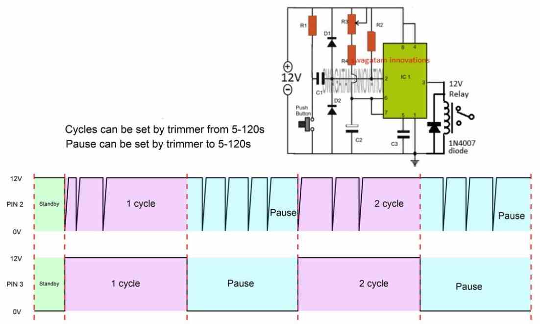
Thanks.
For this you can use another 555 circuit configured as an astable oscillator, and then disconnect the monostable 555 timers pin#4 from the positive line and connect it with the pin#3 of this astable 555 oscillator.
Let me know if you understood the connections or not…
I don’t understand the connection. Can you draw circuit diagram it for me.
Thanks.
You can do it in this way:
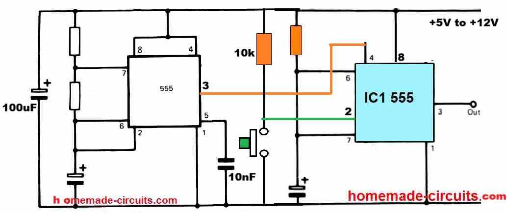
It works Thanks. You are genius!
You are most welcome, glad it worked….
Sir, im SASHIKA from sri lanka. i want to make a polyethene sealer machine for my privet purpose, its hard to find a proper variable timing circuit for it. can you please send me a proper circuit diagram for it.
circuit work direct 230v, and heater work with 12v t/f
Hello Sashika, You can try the 3rd circuit from the above article?

For the 12V operation you will have to use a 12V transformer power supply or an SMS because your heater is 12V.