In this post we are going to build a drag race timer circuit using a 7 segment display and commonly available discrete components which can measure the time taken for a car or any other vehicle from start line to finish line. The proposed circuit is fully automatic, meaning it can start and stop the timer without human intervention.


We will explore the following:
- What is a drag race?
- What is a drag race timer?
- Block diagram of drag race timer.
- Circuit diagram and description.
- Simulation files and circuits.
- Operating instructions.
What is a drag race?
It is a race between two cars over a short distance on a straight track called dragstrip typically for quarter mile (402 meters) or 1000ft (305 meters) or 1/8th of a mile (201 meters), the first one to reach the finish line wins the race. Drag racing cars can reach top speed very quickly and are modified to do so.
What is a drag race timer?
A drag race timer is essentially an automatic stopwatch that measures the time taken for a car to reach the finish line from the starting point. The timer can be analog / manual (back in the days) or digital (modern day) with very high accuracy.
Electronic timers and speed sensing systems were introduced as early as the 1960s. Modern-day real-life drag race timers can measure data like average speed, reaction time, elapsed time etc. and is controlled by microprocessors and provides instant results on a display as big as advertisement billboards.
In this post we will be constructing a miniature drag race timer which can measure race time with reasonable accuracy.
Block diagram of drag race timer:

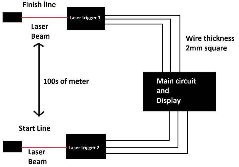
The proposed drag race timer circuit showcases the elapsed time on 5 x 7 segment display, the start and finish points are equipped with laser trigger circuit which automatically detects a car when the laser beams get interrupted.
The two laser trigger circuits are interfaced with a bistable multivibrator. The bistable multivibrator is responsible for triggering the astable multivibrator which provides clock signal for the counter stage.
When the laser at start line gets interrupted, the bistable multivibrator sends continuous high DC signal to astable multivibrator stage which makes it oscillate at 1 KHz which is the required clock signal for the display counter stage.
When the car reaches the finish line another laser beam gets interrupted which makes the bistable multivibrator’s output to go low which halts the astable multivibrator’s oscillation at the output which eventually freezes the time on the 7 segment display, thus a reading is obtained.
Circuit diagram:
- Laser trigger circuit:

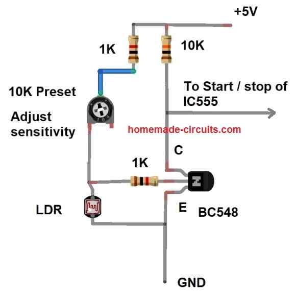
The above functions like this: The output of the circuit is active low, when the laser beam hit the LDR, output gets high and when the laser beam is interrupted the output goes low which is necessary for triggering the bistable multivibrator stage.
The laser trigger circuit consists of a low power NPN transistor, LDR for detecting laser beams, a preset / potentiometer for adjusting sensitivity and a couple of pull-up resistors.
When the laser beam hits the LDR, its resistance drops significantly and ground signal will pass to the base of the transistor which makes the transistor off and since there is a 10K pull-up resistor at the collector terminal, the output of the circuit turns high.
When the laser beam is interrupted LDR’s resistance increases significantly, now +Ve signal via preset resistor pass to the transistor’s base and turns ON the transistor which makes current to flow from ground to collector terminal making the circuit’s output low.
A 1K ohm resistor is connected in series with the preset resistor to prevent short circuit when the LDR’s resistance is very low (when laser beam hits LDR) and when you accidentally turn the preset to minimum position (low resistance). Another 1K resistor is connected to the base of the transistor to limit the current flow to the transistor.
- Laser setup:

The LDR should be mounded inside a hollow tube painted black inside and make the tube at-least 5 cm long so that ambient light or sunlight can be blocked effectively. Try to get a laser diode that is powerful enough and visible even on bright sunshine (with 100mW optical output or suitable one).
- Counter, display driver, bistable and astable stages:

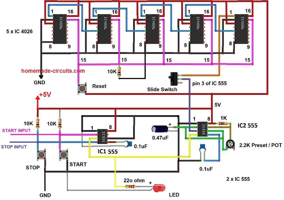
The above circuit is the brain of the drag race timer which does automated computing of time elapsed when a car reaches from start to finish line. Let’s try to understand each stage in the circuit.
There are two IC 555s one of them is configured as bistable and another one as astable multivibrator. The IC 555 present at the left hand side is configured as bistable (IC1) which get its input from two laser detector circuits, one at the start line and another one at the finish line.
When a car interrupts the laser at start line, pin #2 of IC1 555 gets low momentarily which makes the output pin #3 to go high. The pin #3 is connected to IC2 555’s reset pin #4; this makes the IC2 oscillate at 1 KHz.
When the same car interrupts the laser at finish line, pin #4 of IC1 gets low momentarily which makes the pin #3 to go low and when low signal is fed to pin #4 of IC2 (555) the output halts oscillation.
There are two push buttons provided beside IC1 555 to emulate start and finish line laser interruption for testing and debugging purpose.
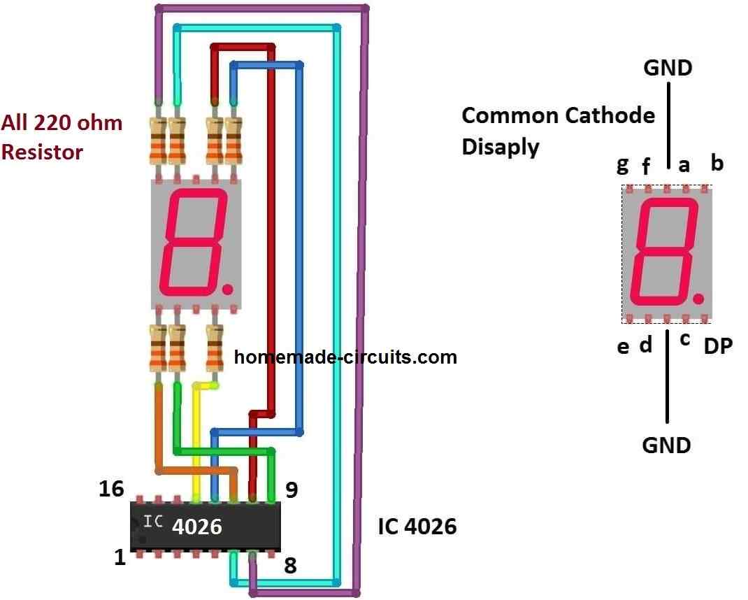
The 1 KHz oscillation is fed to IC 4026 which is capable of counting from 0 to 9 on a common cathode 7 segment display and by cascading five IC 4026s as shown in the schematic we can count from 0 to 99999. The counts we get on the five 7 segment displays are milliseconds and seconds.
A reset button is provided to reset the time count to zero. A slide ON/OFF switch is provided to connect and disconnect the clock signal line from IC2 (555) to the display cum counter stage; exact functionality of the slide switch will be explained later. A LED is provided to indicate that astable multivibrator stage is triggered on.
Please adjust the 2.2K potentiometer to get precisely 1 KHz at pin #3 of IC2 555; the accuracy of the time elapsed depends on this calibration.
IC 4026 to common cathode display connection:


Simulation:

We verified the functionality of the circuit using proteus simulation software; here instead of the laser trigger circuit we made an equivalent function using software push buttons for starting and stopping the timer.
Please click here to download the simulation file.
Wire length and thickness:
The proposed circuit can be deployed for a track length of several 100s of meters; the only requirement is we need to choose a transmission wire with appropriate thickness. We recommend wires with thickness of 2mm square from laser trigger circuit to the main circuit (Vcc, GND and output).

How to operate the circuit:
The below given explanation is applicable for practical and simulation circuits.
- The slide switch must be in the off position before you turn ON the circuit.
- Now, switch on the circuit and you will see that the LED is turned ON and count on the display is 00000, the glowing LED indicates that astable multivibrator is generating oscillation, this is because the bistable multivibrator’s initial output will be high which triggers the astable multivibrator to oscillate.
- Press stop button (at pin #4) which will turn off the LED and oscillation, now toggle the slide switch to the ON position. Now your circuit is ready for a race.
- To emulate a race, press the start button or interrupt the start laser beam that hit the LDR, you will see the display start counting the time.
- Now press the stop button or interrupt the finish line laser beam and you will see the time elapsed on display.
- Press the reset button to reset the count to zero and start a new race. Repeat the same procedure when you turn ON the circuit next time.

Could use drag tree plan,with red guard
Working very nice, should make printed circuit board to sell
Thanks for updating. Glad it is working.
I am looking for a circuit diagram for drag racing timer/ display that can power 7 segment 12 v leds.
The above explained circuit uses a 7 segment display using. The above circuit should work with 12V also…
okay i’ll try it thank you
One of the good thing that can happen to a good learner is to go along with your teaching and practical works. Wonderful one more strength.
I just got to know your site and page and it is amazing and i have chosen to build i mean learn from you.
Thanks
Okonkwo Andrew
Thank you for sharing your feedback, I appreciate your thoughts!