IC 555 adjustable timer explained here can be adjusted from any time delay 1 second to 3 hours for operating any load through a relay control
The produced time delay is fully adjustable and the user has the freedom to set the time period as desired.
There are many ways of making simple timer circuits using different ICs and discrete components; here I have explained one such circuit using the ubiquitous IC 555.
The IC 555 is a pretty common electronic part among the electronic enthusiasts and is also very popular due to the involved simple configurations and low component count.
The two popular multivibrator modes of operation that’s associated with this IC are the astable mode, and the monostable mode. Both of these are useful configurations and have plenty of different applications.
Using the IC 555 in Monostable Mode
For the present adjustable IC 555 timer circuit design we incorporate the second mode of operation, which is the monostable mode.
In this mode of operation the IC is configured to receive a trigger externally, so that it’s output changes state, meaning if with reference to the ground if the output of the IC is zero, then it would become positive as soon as the trigger (momentary) is received at its input terminal.
This change in its output is sustained for a certain period if time, depending upon the external time determining components. Normally the time determining components are in the form of a resistor and a capacitor which together determine or fix the time period for which the IC output would hold its “high” position.
By changing either the value of the capacitor or the resistor, the timing can be altered as desired. The above time fixing components are termed as the RC component.
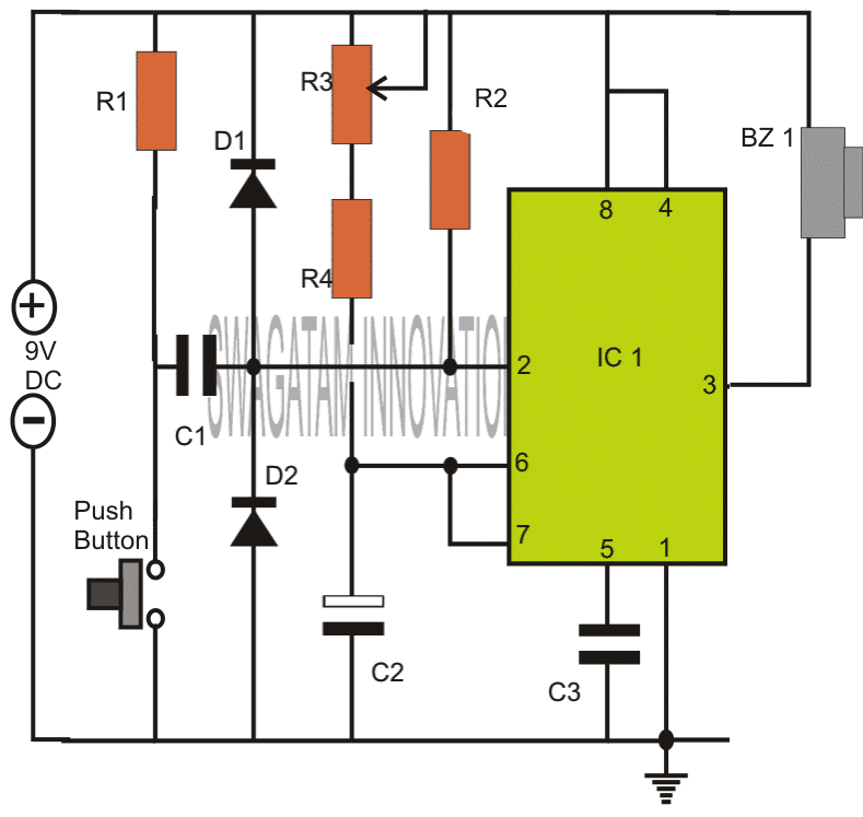
Note: Please connect the buzzer or the load between pin#3 and ground, and not between pin#3 and positive as incorrectly shown in the above diagram.
How the Circuit Functions
The 555 IC timer circuit above shows a very straightforward design where the IC 555 forms the central controlling part of the circuit. As discussed in the above section, the IC is in its standard monostable mode.
Pin #2 receives the external timing trigger from a push-to-ON switch. Once this switch is pushed, the circuit pulls its output to a positive potential and holds it until the predetermined time delay lapses.
The entire circuit can be built over a small piece of general PCB and housed inside a neat looking plastic enclosure along with the battery.
The output may be ideally connected to a buzzer for receiving the warning alarm after the set time lapses.
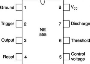
Parts List
- R1, R4 = 4K7,
- R2 = 10K,
- R3 = 1M pot,
- C1 = 0.47uF,
- C2 = 1000uF/25V,
- C3 = 0.01uF,
- IC1 = 555,
- Bz1 = Piezo Buzzer,
Push Button = push to ON switch circuit design requested by Mr.Bourgeoisie:
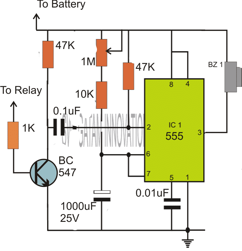
Please connect the buzzer or the load between pin#3 and ground, and not between pin#3 and positive as incorrectly shown in the above diagram.
Timer Circuit with Relay Switching
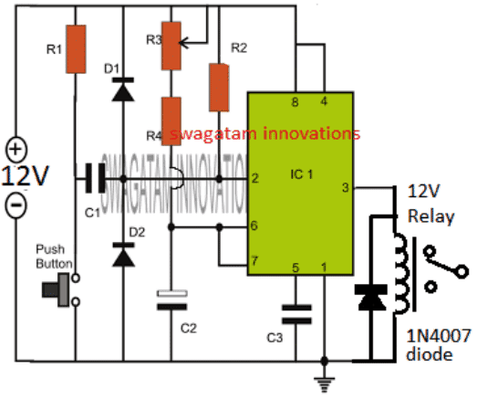
If you are wondering how the above simple timer circuits could be used for triggering a high power load through relay switching, then the following diagram will help you to implement the same by attaching a simple relay stage with the shown designs:
Parts List
All resistors are 1/4 watt 5%
- R1, R4 = 4K7,
- R2 = 10K,
- R3 = 1M pot, Linear
- C1 = 0.47uF Ceramic disc or PPC,
- C2 = 1000uF/25V, Electrolytic
- C3 = 0.01uF, Ceramic Disc
- IC1 = 555,
- Diode = 1N4007
- Relay = 12V/400 Ohm relay,
- Push-button = Any push-to-ON switch
Circuit Operation
In the shown diagram, when power is switched ON, the IC goes into a standby state, and no triggering action is initiated at this moment.
However as soon as the push button pressed, pin#2 is pulled down to ground which instantly triggers the IC in the monostable counting mode, and the relay is activated. The load connected with the relay is thus also activated.
The IC starts counting, and depending on the values of R3/R4, and C2, once the timing period gets elapsed, the IC resets to the previous standby mode deactivating the relay. The relay load also gets deactivated in this situation.
The cycle repeats each time the push button is pressed, enabling the user to achieve the relay triggered timing ON OFF feature in the circuit.
The timing interval can be increased or decreased to a given extent by suitably altering the pot R3 value and/or by modifying the value of C2.
Prototype Images
The above explained 555 adjustable timer circuit was successfully built and tested by Mr. Vee, who is one of the dedicated readers of this blog, and a serious electronic hobbyist.
The circuit was appropriately modified to suit his personal timer application. The modified image can be viewed in the following diagram:
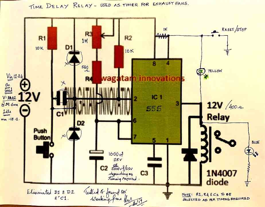
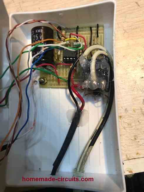
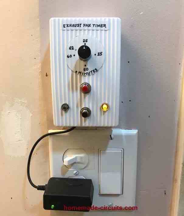
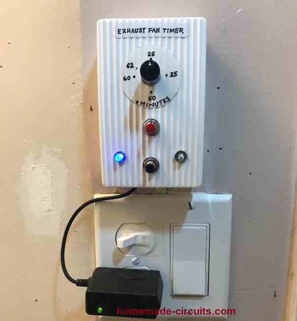
The prototype images of the above timer unit can be witnessed as shown below (built and tested by Mr. Vee):



Questions & Answers
Hi swagatam ,I wanted to construct a circuit which uses a small voltage of less than one volt to control a relay of 12 v.how can I go about?
Hi Ben,
You can try a relay driver circuit as shown here:
https://www.homemade-circuits.com/2012/01/how-to-make-relay-driver-stage-in.html
You can try this circuit:
https://www.homemade-circuits.com/2013/07/simple-triac-timer-circuit.html
You will have to remove D2 and replace the triac with a transistor/relay driver stage, after that the variable may be set for achieving the required timing.
Hello sir, I have formed this circuit in multisim 12.o. i have the muscle stimulator as the other circuit. can this muscle stimulator be the trigger?? if i put these two circuits on 1 board in multisim, will the result show??
Hello sir. I just wanna ask if i put this circuit and a muscle stimulator circuit as the trigger in multisim 12.0, will the result show, like the buzzer would buzz? or it should be done physically to know the results??
Hello Jaejjii,
I don't think the simulator would be able to simulate your muscle simulator response along with the above circuit….so I think you should test the configuration practically.
hello sir…fist of all thank u for running such a nice blog…sir i want to make a three light running chaser to be worked on ac lights…and want to keep interval switching time 1 minute…pls pls help me sir….thanxx
Helo Nitin,
I have explained it in your previous comment with a link….for 1 minute interval you just need to adjust the pots carefully for the required timing.
You can try the second circuit given in the above article, do the following modifications in it:
Remove the buzzer, and put a relay across pin3 and ground.
Remove the transistor and replace the position with a 0.22uF capacitor, also put a 1M resistor in parallel with the above cap.
The timing can be set by adjusting the shown preset.
Whenever power is switched ON, the relay will hold and then deactivate after the delay period has lapsed.
The reay contacts may be wired up with the hair dryer.
Hi Swagatam
Would you please tell me the functions of D1, D2 and R1? I have just blew a 555 without them.
What would be the configuration for a positive triggering signal?
Hi Abu-Hafss,
R1/R2 are for discharging C1 so that it becomes ready for the next input pulse
D1/D2 are not crucial and may be removed, these are for restricting the entry of high frequency disturbance at pin2 and for eliminating false response by the IC.
There's no way you can blow this IC, unless you short circuit the output for too long or reverse the supply polarity…..
You will have to construct it first and then check it as per the given instructions, that's all. If you face problems while troubleshooting I'll help you.
Hi Swagatam
I am really exhausted, I admit, I have failed. Please help me.
I need two monostable 555 timers configured such that:
1) when switched on, ONLY the first timer should be triggered automatically
2) after completing its preset time the 1st timer triggers the 2nd timer
3) after completing its preset time the 2nd timer triggers the 1st timer
4) hence the cycle repeats indefinitely
Just let me know how to connect the pin #2 of both timers.
Hi Abu-Hafss,
I'll do it for for but in return you will have to explain the circuit in your own words, …agreed?
Okay………………
Actually, I had made the circuit; and as per my usual practice I simulated in 2 different softwares. One worked perfectly, but the second one (LTSpice from Linear Technology) did not accepted. And I mostly rely on LTSpice, which I consider to be much accurate.
Here is my circuit
Hi Abu-Hafss,
The trigger inputs are not configured correctly in your circuit according to me, I'll try to update the correct one soon.
Hi Abu-Hafss,
Please refer to the "sequential timer" section in the following pdf link:
http://www.ti.com/lit/ds/slfs022h/slfs022h.pdf
Hi Swagatam
The link shows monostable timer with manual triggering whereas, I was talking about automatic triggering at power-up.
If for example we have 3 sequential timers:
a) Only the first timer should start at power-on.
b) The first timer should trigger the second.
c) The second should trigger the third.
d) The third should re-trigger the first one.
My problems is how to restrict the 1st timer to be triggered automatically at power-up?
According to my observations, sometimes 1st timer gets triggered, sometimes 2nd, sometimes 3rd, sometimes all three and some times none.
Hi Abu-Hafss,
Replace the switch "S" with a 1uF capacitor and also connect a 10k resistor across the positive and pin2 of this IC, now the circuit becomes an automatic sequential timer as soon as it's powered up.
The circuit will always start from IC1 when switched ON as per my simulation, just try it.
Good afternoon sir,
Would U kindly mention the value of D1 & D2.
Wheather a 6v relay will work instead of a buzzer?
Inform the caution to be taken for 6v supply instead of 9v d.c.
Thanks …………….
k.kausik
Kaushik, D1, D2 are 1N4148 diodes
6V relay can be used but the supply should be also at 6V
the same circuit can be used for 6V operation also, no changes would be required.
Good evening sir,
Wishing you a hearty thanks for your kind reply…….
A request ;
A search option & "go to top" is needed on your web page……. So many useful circuits …a huge no of posts & comments…..
With regards,
K.Kausik
Thank you Kaushik,
Your suggestion is very good.
If it's possible to include this feature in my blog template, I will make sure it gets implemented soon.
….by the way the search option is already there at the left top of sidebar.
sir, can i use the same circuit above using a 12volts power supply? or do i have to modify some of the parts?
Jomel, 12V can be also used for the same circuit, no changes would be required
Hey Swagatam,
I like ur circuit and i am new to electrical world.
So i want to know that if i have an input of 220 volt ac , what value of resistance i must have to add do that i get output of 9 volt ac
Thanks Vipin,
If you are referring to the above circuit, for a 220V operation you can use a 12V AC/DC adapter for it…..12V would also work for the above circuits.
sir,i'm planning the same circuit above to control a motor of 12v, 8 amps for a certain time duration,i attached a tip3055 transistor in series with a 1M resistor to the output in place of the buzzer, will that work?
Jomel, you will need to do it via a TIP122 transistor.
connect the base of TIP122 to pin3 of the IC via a 1k resistor.
connect the emitter of TIP122 to the base of TIP3055
connect the emitter of TIP3055 to ground.
join the collector of both transistors and connect it to the negative of the motor, and connect the positive of the motor to positive of the supply.
Hi Swagatam
TIP122 is a darlington pair, so shouldn't it be replaced with TIP31?
Otherwise, what would this configuration be called i.e. 3 transistors connected in series with common collector?
Hi Abu-Hafss,
Here we are looking for a guaranteed and an optimal switching conditions for the 2N3055 since the source current is very low in mA.
Therefore a Darlington is a better choice since it would ensure the full dose of current for the 2N3055 producing an optimal switch-ON for the load
OK,thank you sir,i will try and see what will happen
Sir,may i ask what is the reason behind the additional transistor tip122?
Jomel, for 8amp collector load, the base of 2N3055 would require around 200mA current, TIP122 is used for optimally satisfying this amount of current to the base of 2N3055
Good morning sir,
My android mob. is the only way to connect with Net. It's quite tough to search any particular ckt. Plz. Help!!
I need to convert 12v a.c to 12v d.c
A tr. manufacturer told that when a bridge rectifier is added with the out put of 12v d.c it increases the voltage upto 3v. Is it true? Then what should I do….
1)A tr. of 9v d.c out put…
2)any ckt. that provides 12v a.c to 12v d.c using a tr.
Please guide.
With regards, k.kausik
Hi Kaushik,
yes that's right. in fact with a filter cap it could rise upto 16V
you can use a 7812 IC for restricting the voltage to 12V or add 4 to 5 rectifier diodes in series with the positive for the same.
the diodes could 1N4007 or 1N5402 depending upon the output current specs
I want to make a circuit which work's like I have 9 25 watt clf bulbs and I want to do that when I switch off the first CLF then after each 5 minutes the remaining light would switch off regularly like each should go off after 5 minutes of other means that in 45 minutes all 9 lights go off respectively.So in this case would the last circuit among the drawing's will work or not.Please help me ?
I'll try to design it soon and post it in this blog.
Hello Swagatam i wanna ON my Banner Light with 555 Timer IC for particular hours like 6-8 Hours and then i wanna off it automatically. Is it possible? Please help me regarding this. it will be helpful for me.
Hello Nipun, a 555 IC circuit may not be suitable for acquiring such long delays due to its inefficiency, a 4060 IC is recommended for this as explained in the following article:
https://www.homemade-circuits.com/2013/07/simple-triac-timer-circuit.html
try the second one for your application
how to increase time duration of this timer? like 4 hours timer
by increasing the values of R3/C2
Hello.
If I changed the voltage to 15V, will the values of other components change? If yes, then what will be their new values?
Hello, nothing will need to be changed for 15V, however at 15V the IC can get a bit warm so it's not recommended.
Hello Swagatam, I would like to know if an IRS2453 can be driven by an external oscilator, like UC3845. I want to use this circuit to drive a H bridge in a welding inverter.
Hello Alexandru, According to me it does not include this feature, it can be programmed only through the specified Rt/Ct network….
hello sir,
i want to make a bathroom light timer switch with IC555, but i want to add a warning alarm sound before the lights goes off when the time limit is reached, can you help me?
Hello Enrico, I can certainly help you, please let me know what type of buzzer and lamp do you intend to use in this application.
buzzer is DC type and lamp is fluorescent type…what im trying to do is to make it give a warning sound(somewhere about 15 seconds) before the timer switch the lamp off.
the timer is adjustable from 1-10 minutes