The article discussed here provides a simple, cheap home theater system circuit that may be built at home and used for the desired purpose.
Introduction
The results from this circuit design are outstandingly rich and have the capabilities comparable with the costly hi-end types available in the market.
Home theater systems are quite common nowadays and probably every one of us has one in their homes.
However most of you might be quite unsatisfied by the results of these commercial brands and makes, or probably many of you are completely unaware of what a truly efficient home theater system really sounds like.
Let’s study the design elaborately with the following points:
Basically the circuits discussed are all active tone controller configurations designed for controlling different frequency bandwidth discretely and reproduce the outputs at the respective speakers.
The speakers are also specifically chosen and integrated with the relevant stages for acquiring the most optimized results.
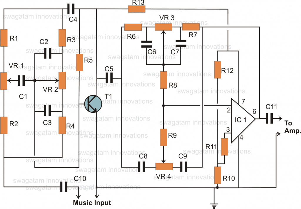
Looking the shown circuit above, the design is a typical tone controller circuit, having discrete bass and treble controls.
The first section incorporates a transistor which solely becomes responsible for the required frequency dimensioning functions. The relevant pots are used for getting the desired bass and treble enhancement effects from the circuit.
How the Circuit Functions
The CIRCUIT DIAGRAM is pretty simple and yet provides very cut and boost with the relevant bandwidths. The second stage which utilizes the IC 741 is also a bass, treble control circuit, however since an IC is used the effects become much enhanced than the previous stage and again the results can be discretely monitored and implemented using the relevant pots associated with the circuit.
It can be clearly seen that the above discussed two stage are connected in series. It means the obtained music and speech enhancing features from the individual units now become intensified to much sharper and magnified extents, but the results still are quite controllable to the desired any desired limits using the four pots associated with the individual stages.
The above units may be optimized to receive audio outputs having intense and heavy bass effects or the results may be trimmed to highlight extreme “chilling” treble effects from the outputs.
Two of the above circuit assemblies may be built separately for making the ultimate home theater system circuit, meaning you will finally have eigt pots to control for achieving any desired levels of optimized sound levels. The above units need to be amplified though, before the effects can be truly enjoyed through the relevant woofers and tweeter units.
If you already own or intend to procure a ready made amplifier, then the above units can be simply introduced in between the audio source and the amplifier input, or if you are a complete electronic freak, you may want to make the amplified section also all by you.
A stereo amplifier circuit design is shown below, one of the channels is used for driving the woofers and the other one is used for activating the tweeters.
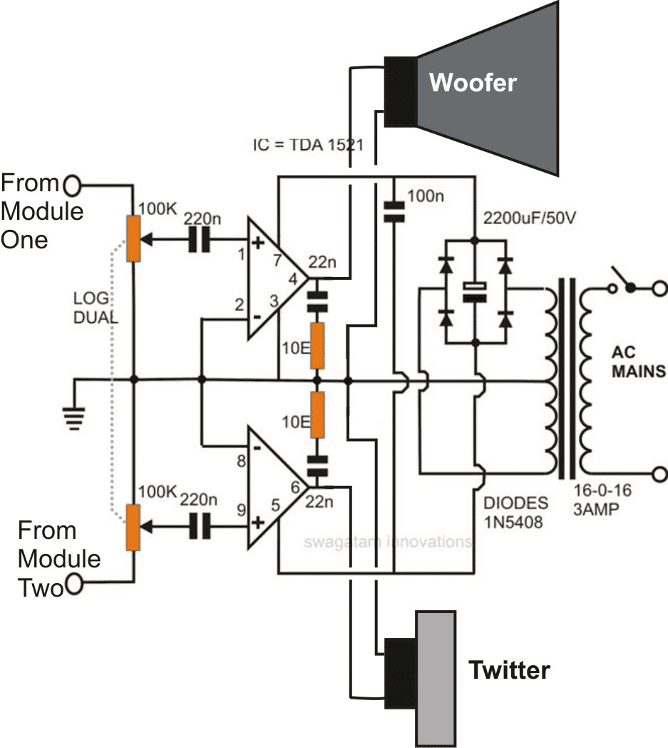
A couple of modules discussed in the above section will need to built and connected to the shown stereo amplifier circuit for completing the proposed home theater circuit design.
Parts List
R1, R2, R3, R4, R5, R9 = 2K2,
R6, R7, R8 R10, R11, R12, R13 = 10K,
VR1, VR2, VR3, VR4 = 100K, LINEAR POTS,
C1 = 0.1uF,
C2, C3 = 0.022uF,
C4, C10, C5, C11 = 1uF, non polar,
C6, C7 = 0.033uF,
C8, C9 = 0.0033uF,
T1 = BC547B,
IC1 = 741


Questions & Answers
Hi I have stk4133ii ic. google don't have any amp circuit of this ic. 🙁
you can try replacing the IC in the following circuit, it could possibly work:
https://www.homemade-circuits.com/2012/04/make-this-powerful-200200-watts-car.html
sir you can give me the pcb layout of thus circuit with component name . and the total circuit of internal in home theater . my email id is satydeep143@gmail.com
please i really need this
Satyadeep, possibly i'll try to post it as soon as i become free from the schedule work
can you give me the full internal circuit on pcb with component name of sound box which on using current and input through 3.5mm jack please sir give me details on my id in pdf please please
where should i connect the positive terminal of the input voltage supply in the first diagram? should it be between C4 and R13? and what is the ideal voltage supply for the first circuit?
where should i connect the positive terminal of the input voltage supply in the first diagram? should it be between C4 and R13? and what is the ideal voltage supply for the first circuit?
connect positive to pin7, negative to pin4 of IC1, ideal voltage is 12V
Is it possible to replace the non polar 1uF capacitors by the polar ones because the non polar ones are not easily available ..or is it possible to replace the non polar 1uF capacitors with the non polar .1uF disc capacitors?
non polar will work better…use two 0.47uF in parallel for making one 1uF cap, or 3nos 0.33uF in parallel will also work…all these could be disc ceramic type
0.1uF is 10 times smaller than 1uF, it won't give proper results.
Sir what specs of woofer and tweeter i should use for the above circuit?
you can use any standard woofer/tweeter set, just make sure that their wattage rating is well over the amps max wattage rating
Thank you Sir, what about the power supply of the first circuit if i duplicate the circuit, should i use two 7812 regulator for one of each or no need for regulator just one power source with higher amps?
I think you can extract 16V from the amp power supply and use it for the first circuit, a 7812 may not be required.
Sir can i get the 12 volt power supply for the first circuit from the power supply of the second circuit by using a 7812 regulator?
Marife, yes you can take out 16V from the power supply positive and the center tap of the transformer
Hello Sir, you mean i can power up the first circuit with 16Vdc? but you said 12Vdc is the ideal input Sir?!
Can i Use an ordinary log dual pot Sir? and can i use a 200watts 8ohm woofer and a 100watts tweeter or the higher wattage the better Sir?
what about an additional output for a sub woofer Sir, it is possible here? How to connect it Sir?
Hello Marife,
I said this because 12V is the standard value and is mostly specified for operating electronic circuits, but since the IC 741 can handle upto 20V so 16V can be used for the first circuit.
Sir, what is the maximum wattage ratings of the above stereo amplifier?
Do you have a SUB WOOFER Circuit/ Link that can be added to the above circuit?
it's 12 + 12 watts for the amp.
you can probably use a simple low pass filter with this amp for getting a subwoofer effect from the design.
Hi Sir, i got online a sub woofer low pass filter and a 100w sub woofer amplifier,
would you please help me how to connect this two separate circuitry with the above stereo amplifier circuit pls!
i already get my new 12" woofer and 150w tweeter this morning and i'm planning to buy tomorrow a 12" sub woofer. So please Sir help me make it done. thanks
Hi Marife,
when you have bought the 100 watt amplifier why would you need the above 12 watt amplifier??
Hi Sir, sorry what i mean is i got online was a circuit for low pass filter and a circuit also for a 100 watts sub woofer amplifier.
Sir you're saying that once i have already the above stereo amplifier, i don't need a separate 100 watt amplifier for the additional sub woofer?
how will i connect the sub woofer with the above stereo amplifier? please…
Hi Marife,
feed the music to the input of the two identical low pass filters, then connect the outputs of these low pass filters with the inputs of the amplifier, the subwoofer speakers can be directly connected with the outputs of the amplifier channels.
all the ground connections should be made into a common line for the above connections.
You mean adding a SUBWOOFER has nothing to do with the above tone control and stereo amplifier because subwoofer has its own filter and amplifier connection?
so i will connect the input of the low pass filter parallel to the input of the above tone control circuit just to share the music input?
sorry Sir i just really have no idea.
if you are using a low pass filter along with a subwoofer then the first circuit cannot be used, because the low pass filter will allow only the low Hz and block higher frequencies…
hi sir i really want to build this but i dont have a layout on pcb. can you help me sir?
Hi Allan, you can follow the part connection layout of the circuit and design the PCB yourself by following it exactly as given, it won't be difficult I can assure you that…
Mujhe module one or module two ye kya hai. Jara samjhaie aur audio connect kaisay karu kush samjh me nhi aa raha hai
you'll need to make two circuits for the first one, and then connect the outputs of the these two circuits with the second circuit inputs marked as module1 and module2.
sir, i'm planing to build both of these circuits. i wanna know can i use this as a mono amp? using only one channel? if can, how to connect the inputs of a 3.5 output to the circuit?
yes you can do it by eliminating one of the volume controls of the second circuit, and by joining the 220n capacitor ends together and connecting it to a single pot.
Sir, i made both circuits. But there is a sound like a motor runing from the speakers but no music. Also the rectifier bridge gets extreamly hot. I checked the transformer & its completely fine. Also the wiring is in order. What could be the problem? Please help me here..
කොටා, I think you might have done something wrong with the amplifier connections or the amp IC is faulty.
check the amplifier separately by feeding music from a cellphone headphone socket, once the amp functioning is confirmed then you can go ahead with the tone control integration
Thank u sir, i wii try that. Btw the transformer is 2A. Is it enough?
yes that's OK.
Sir I have (160w)x2,(60)x2,(1w)x2,15oms,16oms,5oms,,,,,plz give me the design to build sound system
chethan, do you have an amplifier?
hi can you suggest a simple but effective circuit diagram for a 2 channel stereo to 6 channel (5.1)converter?I ask this because i got a 5.1 channel amplifier board from an electronic shop.It has 6 channels…. front(L),front(R),rear (L),rear(R),Center, and subwoofer.The problem is I have only 2channels out from my computer or from my purchased USB board.For subwoofer I guess I have to connect it to a subwoofer filter.And what to do for the rest?
Hi, you can try the following IC for making the required circuit:
https://www.homemade-circuits.com/2012/08/exploring-ic-tda-7560-4-x-45w-quad.html
What is the differences between STK4141-II.stk4141-v.stk4141-AF…what is the difference II.V.AF
Sir i liked this circuit very much… But i am thinking of making a 5.1 surround sound system which composes 5 speakers capable of handling 100 jz to 15 Khz frequencies and one subwoofer to operate in low frequencies.. as it name indicates the system must be capable of routing the audio tracks to these speakers and the woofer according with the behavior of audio. it should have a logical circuitry for that can you please suggest a most efficient circuit for this which can be built on less expense please… i am waiting for your valuable reply and suggestions …
I think you can refer to the following processor circuit, although it does not have a frequency identifier circuit, it will do the basics of a true surround sound system.
https://www.homemade-circuits.com/2016/06/simple-surround-sound-decoder-circuit.html
the circuit will require an amplifier for which you can try interfacing the following design:
https://www.homemade-circuits.com/2012/08/exploring-ic-tda-7560-4-x-45w-quad.html
sir what is the maximum power that can be delivered by this system ?
will a 100 W sub woofer be able to produce its maximum efficiency with this circuit ?
Hi Rt, if the external amplifier is rated accordingly, then definitely that will be possible.
sir i dont need any 7560 ic to interface with this circuit since it is very expensive
I think it won't be required as the circuit by itself is a SS processor
hi SWAGATAM for the second circuit(amplifier), cant a 12V transformer be used ? or it is strictly 16v transformer . if 12V transformer can be used then help me about how to make a rectifier for it to connect to the circuit like type of diodes(either IN4 OR IN5 series) to be used and capacitor rating. this is because i have failed to get a 16V transformer. thanks
Hi Davis, you can use a 12-0-12V transformer and connect it exactly as shown in the diagram….you can use 1N5408 for the diodes
its working professionally thanks SWAGATAM
that's great Davis, thanks for the info
Sir is it possible to use any of these opamps instead of the one which is given in the output driver stage ( TDA1521 ) ?
UA741 or LM324, LM386 , LM358
i dont need a tweeter stage.. so i am skipping the bottom part.. only i need is to get maximum bass response from my 10 inch woofer ( unknown wattage .. i think it is about 100 W)
RT,
TDA1521 is an amplifier IC rated at 12 watts, it cannot be replaced by any ordinary opamp.
for maximum bass, you can put another woofer instead of tweeter, and configure the upper circuit with two bass control circuits and eliminate the treble section…
Sir i have found the ratings of my woofer.. it is a 30W 8 ohm one.. so is it possible to use LM358, UA741 or LM324 instead of TDA1251 ?
No, that's not possible
sir any other simple circuit to operate the 30 W subwoofer ? using power mosfets ( IRG540N ) or power transistors ( 2N5294 ) ?
you can try the following circuit
https://www.homemade-circuits.com/2016/06/simple-20-watt-amplifier-circuit.html
add a low pass filter at the input side for getting the desired bass effect…
what about adding a power transistor stage at the output of an LPF amplifier by lm358 ? and driving the woofer using that transistor ? since my transformer is rated 230/15-0-15 20 A i can easily get a 30 W drive from this… is that so ?
an amplifier is a complex circuit it cannot be made simply by adding power transistors to an opamp…
sir what about giving a +5V -5V dual supply to TL072 ? will it work ?
My speakers are with inbuilt amplifiers .. so they can be easily follows the processed signals…
and do you have any idea to convert a +5 V from a usb device ( power bank, mobile phone etc. ) to -5V and use both as ( +5 V and -5 V as a dual power supply ? )
RT, dual supply has been avoided in the above circuits to keep it simple, although it can be implemented with some modifications.
+5V ad -5V simultaneously cannot be created from a +5V source…..
+2.5/-2.5 may be possible.
Sir Can i use a transformer without centre tap in the last diagram.. one which can deliver minimum of 100 W power at 12 V Secondary voltage?
I dont need the tweeter section .. so i want to skip that portion.. so is that possible to proceed with a transformer without centre tap ?
No, without a center tap the circuit won't work.
for 100 watt you will have use a 100 watt amp, the above amp is rated to provide only 12 + 12 watts of power
4.bp.blogspot.com/-378FzaGwUYc/Tw09YKGnlBI/AAAAAAAAArA/rexDc1WRufo/s1600/Home+Theater.png
does 741 ic requires any power supply in this circuit or it is driven with the music signal only ?
pin#7 will require a 12V positive, mistakenly it is not shown….
(1).sir suppose i am having a 12 V ac from a step down transformer.. i want to convert into 12 V DC. while doing so which diodes are better for BR section to get a minimum current of 6 A ? IN4007 or 1N5408 ?
(2). what will happen if i use 1N4007 to get the required 6A current ? ( if your answer is to use 1N5408, i have a doubt that 1N4007s maximum current handling capacity is about 25A as given in its datasheet so why can't i use that ? )
( transformer is capable to deliver power max. of 300 W )
for the bridge rectifier you must ideally use a diode that may be rated twice the input current…..so for 6 amp current the diode must be rated at 10 to 12 amps.
1N4007 is out of question, since it will start smoking at 1 amp current, and 1N5408 is also out of question as it won't hold more than 3 amp.
Your assumption regarding 1N4007 diodes is grossly incorrect.
so where i have to fix the 12 V supply ? to the 7th pin of UA741 .. right ?
what about the sections before R13 ? Does the R13 actually act as the current limiting section for those stages ?
yes you can connect the supply to pin#7 of the IC, that will do.
R13 limits current for the transistor tone control stage in order to enable it to work efficiently.
sir i had a 300 W transformer with 230 V primary and secondary 12 0 12 centre tapped.. i have reassembled the transformer with multi tap secondary windings such that i get voltages 5, 12, 15, 24 from secondary.. i have used the first wire , 3rd tap( 12 V ) , 5th tap ( 24 V ) to create a 12 Volt dual power supply.. it is working perfectly fine.. The diodes i have used for the FBR sections are 6A4.. so the transformer gives me a pretty decent current of 5 A for a 60 W load
..
but the real problem is something else… i told you that i have taken several taps in secondary.. i have choosen the 2nd tap and first wire to make a 5V dc power supply.. since this tap shows an AC voltage of 4.7 V i got a dc voltage more than 5 ( about 5.7 V ) … i was supposed to connect my usb speakers ( 3 no.s each 5W rated at 5V ) to this supply… since the speakers require a total power consumption of 15W, i have used a 1 ohm , 10W resistor in series with the produced dc voltage in the assumption that current will be limited to 5A max. ( 5/1 ).. and supposed to hold a maximum power dissipation of 25W ( luckily the speakers do not require that much )..
but when i checked the speakers while playing song, a speaker is not actually capable of driving from that power supply.. it produces turn on turn off effect continuously.. to confirm whether this is a problem due to the power supply or not i have connected a dc motor to this … but the result was poor.. the sc motor runs at a spead and torque which is comparatively lesser when it is operated with a usb power bank.. usb power bank drives it more efficiently.. same is the case for speakers… so if u could understand what has really happened in this case please suggest a better remedy as soon as possible…
i need a 5V supply with minimum current delivery of 5 A
RT, you can use an ammeter or the amp range in your DMM to confirm the max current capacity of the relevant trafo taps…it should read above 5amps when the meter prods are connected directly with those taps.
make sure the ammeter is in the 10amp AC range, not DC
sir is it possible to connect a Mosfet based or transistor based 40 W amplifier with a low pass filter circuit with cut off freq. of 200 Hz to drive a subwoofer rated at 40W max. ?
sir can you please suggest an efficient LPF + amplifier circuit for 40 W subwoofer ?
can the amplifier be designed with TIP121 and 127 transistors for 40 W output at supply voltage of +18 V and -18 V ?
RT, you can use the first circuit above for generating the desired low frequency cut off using the pots…..or you can try the following circuit
https://www.homemade-circuits.com/2016/01/design-low-pass-filter-circuit-quickly.html
for the amp you can look for TDA2003 bridged amplifier circuit…..I do not know about any other easier 40 watt amp than this
sir what is the use of connecting one low value capacitor in series with a resistance ( like 22n and 10 ohm in the diagram ) across a speaker terminals ? especially a woofer… what happen if that connection is avoided ?
RT, It could be for bypassing any residual high frequency transient and for ensuring better sound quality…
please give a working or tested tda2003 bridged poweramplifier schematics.
I'll try to publish it soon
hello SWAGATAM, i really appreciate your work, i have few questions though..
1) how to give single audio input to 2 separate audio input terminals in the couple circuits of first stage?
2) should i buy TDA 1521A or TDA 1521Q?
3) where to apply input voltage in first circuit?
lookig forward to your reply
Thanks Humza,
1) you can connect the audio signal simultaneously to both the inputs of the pot, the signal will automatically get divided across the two amps.
2) I think both the variants will work, you can any of those. I am not quite sure about the difference in their specs could be very minor.
3)connect (+) to pin#7 of the IC and (-) to the line which marked with a ground symbol
hey Gawatam,
well i made the complete circuit ( two first stages and the 2nd stage ) and burnt TDA1521A twice , then decided to change input voltage from the 15v transformer to a 12v regulator. now during the 3rd experiment burnt the regulator.
a constant noise could be heard from both the woofer and tweeter but no sign of controlled bass or treble.
i checked the circuit but didnt find any error.
please guide me
Regards
Hi Hamza, you should confirm the different stages separately, first make the amplifier circuit and check it separately by feeding music to the indicated volume controls.
Next make the T1 tone control stage and integrate it between the amp and the music source and check how its bass treble responds.
after that check the 741 separately by attaching with the amp in similar manner as done with the T1 bass/treble control.
finally you can integrate all the stages together to see if all these respond the way they are expected to do.
I have checked the first circuit with some other amplifier and i could find it working perfectly….
Alright im on it.
Kindly tell me, should i Power TDA 1521A directly from 15-0-15 transformer or should i put a 12v regulator in between?
I would suggest you to please visit the datasheet of the IC, from there you will be able to know the exact specs of the amplifier and its safe operating areas.
sorry to disturb you again , as you suggested, i made separate stages. and while testing the amplifier circuit, tda 1521A burnt again. i made the circuit again but still… im lost where the issue is… 🙁
may be your ICs itself are faulty or you are connecting its pinouts wrongly, please check the datasheet of the IC to get more info regarding the device.
hi SWAGATAM the system works fine, now on amplifier side i want to replace the 3 pin 100k pots with 6 pin 100k pots help me how to connect the 100k 6 pin pot
That's great Davis,
the connections will be the same….the center leads of the sets will go to the respective capacitors…one of the outer leads joined together to ground, and the other two individually terminated to the two music channels.
sir I liked it very much. So can you sutable value of woofer and volt.
Thanks, you can use a 4 watt 12 watt woofer
where is terminals to connect speakers
Hi Swagatam,
I have not tryed this practically, but I want to know how to connect this two circuit I mean first circuit's upper module with the second's upper and first's lower with seconds lower?
What should be the rating of the woofer and twitter.
what should be the maximum load of the speakers (if possible)?
Hi Kamaruddin, you will have to make two modules for the first design and connect their outputs with the two pot inputs of the amplifier.
both the woofer and the twitter could be rated at 12 watt each, or you can connect two 10 watt woofers across the two amp outputs and also connect two small 2 watt twitters in parallel with the woofers.
If I make two module then the inputs will be two??. And the outputs of first module should connect both with the amplifier's first pot?? Total pot of frist design will be 8??
C11 of module#1 will connect with one pot of the amp, and C11 of module#2 will connect with second pot.
there will be total 8 pots for the upper modules, to reduce complication use dual pot assembly for the L/R bass/trebles. that will make 4 pots in all.
dual pots will have 6 pins each
I have a filter circuit which i buy near shop so what are The circuits i need for 2.1 home theater
Plese ,I need 5.1 surround sound amplifier cct diagram
hello Mr swagatam, please I need your help on the PCB layout of the above amplifier I mean the one usingTDA1521 ic and the tone controller as well, here is my email Eric I guitars gmail.com
hello Eric, I am sorry designing PCB will not be possible for me, because it’s a lot of work, i’d suggest you to contact a professional PCB designer and get it done from him, if you need any other technical help do let em know.
Pls I need the circuit diagram of tda2030 sound
You can try the following design
https://www.homemade-circuits.com/120-watt-amplifier-circuit-using-tda/