In this post I have explained a simple RC helicopter remote control circuit using 433kHz RF modules, without any microcontroller or complex joystick implementations.
The idea was requested by Mr. Jitendra.
Circuit Objectives and Requirements
- I am making a large scale RC helicopter. In which I am using 4 motors. For 1st main 12v motor: the mechanism is that I want its speed to be controlled by a controller key on the remote, from 0 to full speed.
- For 2nd 3v motors: its mechanism is only for forward and reverse rotation with individual key on the remote for each motors as it will operate the swash plates of rotors.
- For 3rd 9v tail motor: it should be set to an equilibrium speed using a regulator on the receiver board of helicopter so that I could adjust the speed manually to stop the chopper.. from rotating along with the rotors, and there's a key on the remote would be to slow down and speed up the motor from its equilibrium.
- The input power in the receiver board would be 12v and current 8-10 ampere. It should be of range 500-800 meters. Sir can you please design such a RC circuit board along with the remote.
- I am in search of such circuit board since last two years.
- My project was stopped due to its absence. Sir please help me. For your convenience you can design two individual rc circuit boards one for main motor and tail motor and another for two forward and reverse rotating motors.
- But the input current and potential difference in both circuits should be same, with same range that is 500-800 meters with its remotes or remote. Please also mention the name of the components required with numbering.
The Design
The requested circuit modules which are required for building the proposed RC helicopter are:
1) A 12V PWM variable speed controller
2) A 3V motor reverse forward controller circuit.
3) a 9V motor regulator with a variable speed controller circuit.
All the above specifications needs to be controlled via a long range 433MHz RF remote control module.
The desired 433MHz RF remote module could be procured from any online store or from your nearest electronic dealer. The range of the remote control should be as per the required specifications of the RC helicopter range, here it's supposed to be within 1km.
For the discussed RC helicopter remote control circuit, a 6 channel RF remote module would be required, exactly similar to the one which was used for our earlier simplest drone remote control circuit.
The image of the same can be witnessed below:
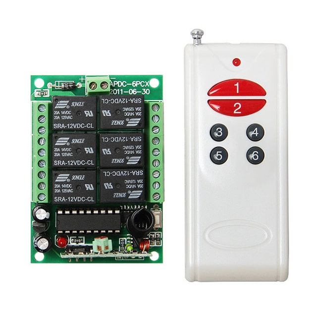
The left side green board is the remote receiver module having the six control relays and this units needs to be installed inside the RC helicopter for the necessary control operations.
The right side unit is the transmitter handset which is supposed to be held by the user and the relevant buttons pressed for commanding the relay board with the corresponding motion control info.
Now lets see how the six relays needs to be configured with the various PWM circuits and installed inside the RC chopper, from the following details:
Remember the relay contacts shown in the receiver board are all blank by default, meaning their N/C and N/O contacts are not wired and must be wired as illustrated in the following diagrams.
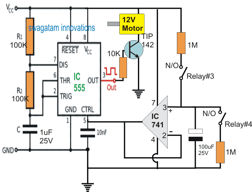
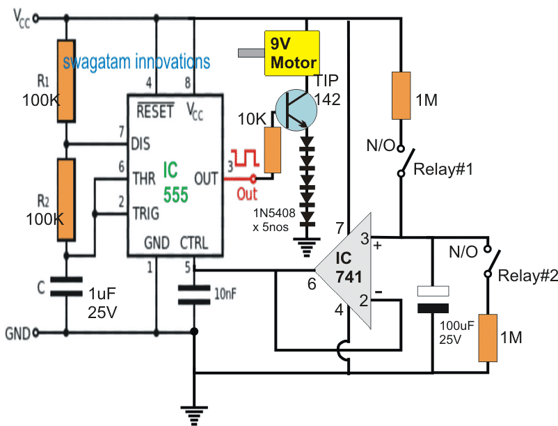
According to the request, the 9V motor and the 12V motor speeds need to be controlled through the subsequent pressing of the remote handset. The circuits for implementing this function are shown below:
Motor Driver Schematic
Circuit Operation
As may be seen in the schematics, a couple of identical IC 555 PWM circuits are employed for the purpose. Four out of the six relays are engaged here with their relevant contacts wired across the shown connections.
In the design the IC 555 is rigged as a basic astable circuit, assigned to oscillate with some specified frequency depending upon its R1, R2, and C component values.
A voltage follower in the form of IC 741 is configured with the control pin#5 of the IC 555 in order to vary the PWM content at pin#3 of the IC 555 in accordance with the indicated relay operations.
The voltage at pin#3 of the IC 741 is followed or transferred at is pin#6 and subsequently to pin#5 of the IC 555. Depending upon pin#3 capacitor charge level this varying voltage could be anywhere between the supply voltage limit and zero.
The charge level on the capacitor is varied or changed by simply charging it or discharging via the relevant relay contact activation. To charge the upper relay contact is closed or activated enabling an rising voltage at pin#5 of IC 555 whereas activating the lower relay contacts discharges the capacitor causing a proportionately lower voltage to appear at pin#5 of the IC 555.
The above actions translate the pin#3 results into a correspondingly varying PWMs which in turn causes the motor to either run faster or slower.
Fro the 9V motor a series of diodes can be seen attached at the emitter of the driver transistor, this ensures the required drop in voltage and helps to convert the 12V into an approximate 10V regulated supply as per the specifications of the motor.
3V Motor Reverse Forward Operation
The third and the last demand in the request is for the reverse/forward control of the 3V motor using the RF transmitter handset button press.
The remaining two relays can eb now used for this particular execution, and is done as demonstrated in the following diagram:

Here also we employ the versatile IC 555 wired as a precise PWM generator circuit. The PWM is set appropriately through the 5K preset before finalizing the installations such that the speed of the motor is perfectly adjusted for the required equilibrium of the helicopter.
The relays can be seen simply wired to enforce the required reverse, and forward or a clockwise or anticlockwise motion for the motor in response to the toggling of the paired relay contact, which together form a DPDT relay.
In order to prevent a short circuit, preferably the receiver module should be modified for these two relays such that pressing either of the buttons causes both the relays to activate together rather tan depending on two switches to be pressed in sync for the activation.
This toggling can be expected to flip the motor rotation in the opposite direction instantly allowing the user to execute the required directional changes in the RC helicopter machine.
This concludes the circuit and relay wiring instructions for the proposed RC helicopter remote control circuit, for further doubts please do not hesitate to express them through your comments.


Questions & Answers
Please send me toy helicopter remote PCB, and components to be used. Please send me your contact number to my contact number 9957604031
Sorry, building the unit may not be possible for me.
sir i want helicopter long range one kilometer circuit dighram complete assembled with remote control plz give me more details. How can I get through you?
Hi Noorul, sorry I do not have a properly tested design…I would suggest you to buy a small ready made model and then reverse engineer it to know the details.
You must buy it just form at home.
Thank you sir for suggestion ????
Sir, how can I get a transmitter/receiver for my portable quadcopter?
You can buy it online…
Hi Swagatam,
I have following doubt in your diagram.
1) regarding 12v motor first diagram. what is the Vcc value ? 12 volt ?
This Vcc will also be supplied to transistor collector but diagram shows that it is connected to 12v DC motor. that means 12v DC motor will require two input ? one from Vcc and another from collector output ?
2) regarding 9v motor second diagram. there are multiple diode attached to Emiter. but couldn’t understand how it is reducing the voltage from 12 Volt to 10 Volt ? and how this 10 V will be as input to 9V DC motor which is connected on collector ?
3) regarding 3v Motor third diagram. why we are using zener diode ? also relay 5 and 6 if they are in existing position will rotate the motor in clock wise direction via relay 5 , but after both the relay switch to another position same time then the motor also rotate in same direction via relay6. I couldn’t understand how the motor will toggle it’s rotation.
Hi Sachin,
All the indicated Vcc points are supposed to be connected with +12V. One terminal of the 12V and 9V motors get the +12V supply from the Vcc line and the negative supply through the transistor, in order to operate. The collector is never supposed to get any 12V.
2) Each diode will drop around 0.7V, so 5 together will drop 0.35V, which will be deducted from the 12V allowing only 8.5 or 8.9V to the 9V motor.
3) The zener diode allows the emitter of the TIP122 to produce a stabilized 3V for the 3V motor.
When relay5/6 are toggled together will reverse the polarity of the motor leads each time, which will correspondingly flip the rotational direction of the motor
I hope this solved your doubts
Thanks for your reply. let me design this and let you know if I face any issue.
Pls sir, will i make pwm signal for bothe the tx and rx section?
PWM is only for RX associated with the reverse forward motor
Sir i am making a rc plane i have a 433mhz module and brushles motor and esc and esc operated by signal so i need a circuits daigram where from i can provide signal to esc control by rf module so sir please gave me a circuits daigram of pwm and components list with his velow i shall very thankful toyou
Hardev, do you have an PWM input for your ESC, and I think you should be having 4 ESC for the 4 motors right? you can refer to the following article for more info
https://www.homemade-circuits.com/quadcopter-remote-control-circuit/
Sir i need whic circuit i can gave signal to rc plane esc cotroled by 434mhz module
Hardev, please provide more information about your requirement, full working specification
Sir I would like to know how to use a 5k pot or knob switch to control the speed of the motor from 0% to 100% through a wireless connection
succeess, It may not be possible in the above concept, I have discussed a related a concept below which uses a varying PWM for controlling the motor speed:
https://www.homemade-circuits.com/2015/10/quadcopter-remote-control-circuit.html
sir I need a circuit diagram for a rc mini helicopter and components name
sir, i need help… anyway not on the above circuit. sir i build a simple inverter using(2) IRF730(MOSFET), (2)MPS 2222A(MOTOROLA), (2)12kohms and (2)680ohms resistor and (2)2.2mf/50v capacitor in this circuit. After finishing the construction i tested it with 12v/7a battery , but nothing happen at the other side of the transformer(outlet). sir i need u to help me point out where i might ve made a mistake. thank u sir
Tun, without seeing the diagram it will impossible for me to say anything, and please comment under an "inverter" related article.