• Skip to main content
  • Skip to primary sidebar

Homemade Circuit Projects

Need circuit help? Post them in the comments! I've answered over 50,000!

Blog | Categories | About | Contact | Calculators-online
You are here: Home / Power Supply Circuits / How to Calculate Transformerless Power Supply Circuits

How to Calculate Transformerless Power Supply Circuits

Last Updated on March 9, 2025 by Swagatam 97 Comments

In this article I have explained how to calculate resistor and capacitor values in transformerless power supply circuits using simple formulas like ohms law.

Analyzing a Capactive Power Supply

Before I have explained the formula for calculating and optimizing resistor and capacitor values in a transformerless power supply, it would be important to first summarize a standard transformerless power supply design.

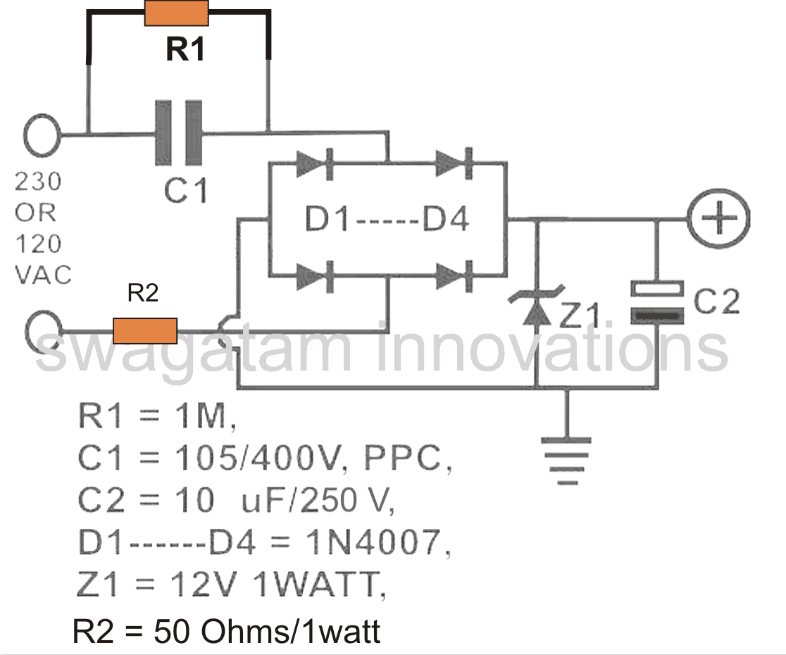
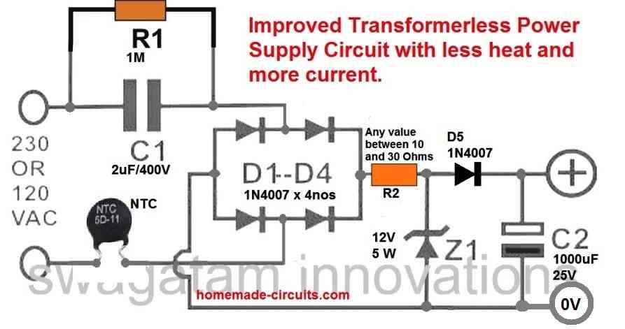
Referring to the diagram, the various components involved are assigned with the following specific functions:

C1 is the nonopolar high voltage capacitor which is introduced for dropping the lethal mains current to the desired limits as per the load specification.

This component thus becomes extremely crucial due to the assigned mains current limiting function.

D1 to D4 are configured as a bridge rectifier network for rectifying the stepped down AC from C1, in order to make the output suitable to any intended DC load.

Z1 is positioned for stabilizing the output to the required safe voltage limits.

C2 is installed to filter out any ripple in the DC and to create a perfectly clean DC for the connected load.

R2 may be optional but is recommended for tackling a switch ON surge from mains, although preferably this component must be replaced with a NTC thermistor.

Using Ohm's Law

We all know how Ohm’s law works and how to use it for finding the unknown parameter when the other two are known.

However, with a capacitive type of power supply having peculiar features and with LEDs connected to it, calculating current, voltage drop and LED resistor becomes a bit confusing.

How to Calculate and Deduce Current, Voltage Parameters in Transformerless Power Supplies.

After carefully studying the relevant patterns, I devised a simple and effective way of solving the above issues, especially when the power supply used is a transformerless one or incorporates PPC capacitors or reactance for controlling current.

Evaluating Current in Capacitive Power Supplies

Typically, a transformerless power supply will produce an output with very low current values but with voltages equal to the applied AC mains (until it’s loaded).

For example, a 1 µF, 400 V (breakdown voltage) when connected to a 220 V x 1.4 = 308V (after bridge) mains supply will produce a maximum of 70 mA of current and an initial voltage reading of 308 Volts.

However this voltage will show a very linear drop as the output gets loaded and current is drawn from the “70 mA” reservoir.

transformerless power supply circuit diagram with calculations

We know that if the load consumes the whole 70 mA would mean the voltage dropping to almost zero.

Now since this drop is linear, we can simply divide the initial output voltage with the max current to find the voltage drops that would occur for different magnitudes of load currents.

Therefore dividing 308 volts by 70 mA gives 4.4V. This is the rate at which the voltage will drop for every 1 mA of current added with the load.

That implies if the load consumes 20 mA of current, the drop in voltage will be 20 × 4.4 = 88 volts, so the output now will show a voltage of 308 – 62.8 = 220 volts DC(after bridge).

For example with a 1 watt LED connected directly to this circuit without a resistor would show a voltage equal to forward voltage drop of the LED (3.3V), this is because the LED is sinking almost all the current available from the capacitor.

However the voltage across the LED is not dropping to zero because the forward voltage is maximum specified voltage that can drop across it.

From the above discussion and analysis, it becomes clear that voltage in any power supply unit is immaterial if the current delivering capability of the power supply is "relatively" low.

For example if we consider an LED, it can withstand 30 to 40 mA current at voltages close to its "forward voltage drop", however at higher voltages this current can become dangerous for the LED, so it's all about keeping the maximum current equal to the maximum safe tolerable limit of the load.

Calculating Resistor Values

Resistor for the Load: When an LED is used as the load, it is recommended to choose a capacitor whose reactance value allows only the maximum tolerable current to the LED, in which case a resistor can be totally avoided.

If the capacitor value is large with higher current outputs, then probably as discussed above we can incorporate a resistor to reduce the current to tolerable limits.

Calculating Surge Limit Resistor: The resistor R2 in the above diagram forms is included as the switch-ON surge limiter resistor. It basically protects the vulnerable load from the initial surge current.

During the initial switch ON periods, the capacitor C1 acts like a complete short circuit, although just for a few milliseconds, and may allow the whole 220V across the output.

This may be enough to blow the sensitive electronic circuits or LEDs connected with the supply, which also includes the stabilizing zener diode.

Since the zener diode forms the first electronic device in line which needs to be safeguarded from the initial surge, R2 can be calculated as per the zener diode specifications, and maximum zener current, or zener dissipation.

The maximum tolerable current by the zener for our example will be 1 watt / 12 V = 0.083 amps.

Therefore R2 should be = 12 / 0.083 = 144 Ohms

However, since the surge current is only for a milliseconds, this value could be much lower than this.

Here. we are not considering the 310V input for the zener calculation, since the current is limited to 70 mA by the C1.

Since R2 can unnecessarily restrict precious current for the load during the normal operations, it must be ideally an NTC type of resistor.

An NTC will make sure that the current is restricted only during the initial switch ON period, and then the full 70 mA is allowed to pass unrestricted for the load.

Calculating the Discharge Resistor: Resistor R1 is used for discharging the stored high voltage charge inside C1, whenever the circuit is unplugged from the mains.

R1 value should be as low a possible for fast discharging of C1, yet dissipate minimum heat while being connected with the mains AC.

Since R1 can be a 1/4 watt resistor, its dissipation must be lower than 0.25 / 310 = 0.0008 amps or 0.8 mA.

Therefore R1 = 310 / 0.0008 = 387500 Ohms or 390 k approximately.

Calculating a 20 mA LED Resistor

Example: In the shown diagram, the value of the capacitor produces 70 mA of max. current which is quite high for any LED to withstand. Using the standard LED/resistor formula:

R = (supply voltage VS – LED forward voltage VF) / LED current IL,
= (220 - 3.3)/0.02 = 10.83K,

However the 10.83K value looks pretty huge, and would substantially drop the illumination on the LED....none-the-less the calculations look absolutely legitimate....so are we missing something here??

I think here the voltage "220" might not be correct because ultimately the LED would be requiring just 3.3V....so why not apply this value in the above formula and check the results? In case you have used a zener diode, then the zener value could be applied here instead.

Ok, here we go again.

R = 3.3/0.02 = 165 ohms

Now this looks much better.

In case you used, let's say a 12V zener diode before the LED, the formula could be calculated as given below:

R = (supply voltage VS – LED forward voltage VF) / LED current IL,
= (12 - 3.3)/0.02 = 435 Ohms,

Therefore the value of the resistor for controlling one red LED safely would be around 400 ohm.

Finding Capacitor Current

In the entire transformerless design discussed above, C1 is the one crucial component which must be dimensioned correctly so that the current output from it is optimized optimally as per the load specification.

Selecting a high value capacitor for a relatively smaller load may increase the risk of excessive surge current entering the load and damaging it sooner.

A properly calculated capacitor on the contrary ensures a controlled surge inrush and nominal dissipation maintaining adequate safety for the connected load.

Using Ohm's Law

The magnitude of current that may be optimally permissible through a transformerless power supply for a particular load may be calculated by using Ohm's law:

I = V/R

where I = current, V = Voltage, R = Resistance

However as we can see, in the above formula R is an odd parameter since we are dealing with a capacitor as the current limiting member.

In order to crack this we need to derive a method which will translate the capacitor's current limiting value in terms of Ohms or resistance unit, so that the Ohm's law formula could be solved.

Calculating Capacitor Reactance

To do this we first find out the reactance of the capacitor which may be considered as the resistance equivalent of a resistor.

The formula for reactance is:

Xc = 1/2(pi) fC

where Xc = reactance,

pi = 22/7

f = frequency

C = capacitor value in Farads

The result obtained from the above formula is in Ohms which can be directly substituted in our previously mentioned Ohm's law.

Let's solve an example for understanding the implementation of the above formulas:

Let's see how much current a 1uF capacitor can deliver to a particular load:

We have the following data in our hand:

pi = 22/7 = 3.14

f = 50 Hz (mains AC frequency)

and C= 1uF or 0.000001F

Solving the reactance equation using the above data gives:

Xc = 1 / (2 x 3.14 x 50 x 0.000001)

=  3184 ohms approximately

Substituting this equivalent resistance value in our Ohm's law formula, we get:

R = V/I

or I = V/R

Assuming V = 220V (since the capacitor is intended to work with the mains voltage.)

We get:

I = 220/3184

= 0.069 amps or 69 mA approximately

Similarly other capacitors can be calculated for knowing their maximum current delivering capacity or rating.

The above discussion comprehensively explains how a capacitor current may be calculated in any relevant circuit, particularly in transformerless capacitive power supplies.

WARNING: THE ABOVE DESIGN IS NOT ISOLATED FROM MAINS INPUT, THEREFORE THE WHOLE UNIT COULD BE FLOATING WITH LETHAL INPUT MAINS, BE EXTREMELY CAREFUL WHILE HANDLING IN SWITCHED ON POSITION.

You'll also like:

  • 1.  12 V to 30 V High Current Boost Converter Circuit [Variable]
  • 2.  0-40V Adjustable Power Supply Circuit Diagram
  • 3.  Variable Voltage, Current Power Supply Circuit Using Transistor 2N3055
  • 4.  12V LED Backpack Power Supply Circuit
  • 5.  15V 10 Amp Voltage Regulator Circuit Using IC LM196
  • 6.  LM317 Variable Switch Mode Power Supply (SMPS)

About Swagatam

I am an electronics engineer with over 15 years of hands-on experience. I am passionate about inventing, designing electronic circuits and PCBs, and helping hobbyists bring their projects to life. That is why I founded homemade-circuits.com, a website where I share innovative circuit ideas and tutorials. Have a circuit related question? Leave a comment.... I guarantee a reply!

Previous Post: « Single Transistor LED Flasher Circuit
Next Post: Simple Peltier Refrigerator Circuit »

Reader Interactions

Comments

  1. Patrick says

    January 5, 2024 at 1:54 am

    Very good and useful analysis for free ,Keep it up sir.I have made all efforts to repair damaged common china rechargeable touch on charging circuit,all to failure.With this analysis and other elsewhere,i made a breakthrough.But its good to go for a capacitor with 8 or 10volts so that if the led indicator drops some volts,there will be enough to charge the 4 or 5v battery.
    But why is it that when you replaced a burnt component in a circuit like the rechargeable touch,still it wont work.
    Thanks so much.

    Reply
    • Swagatam says

      January 5, 2024 at 9:15 am

      Thank you Patrick,
      There may be some other components which are faulty, that is why the device is not working. You may have check each and every component to diagnose the unit fully.

      Reply
  2. Rajat Kumar Sardar says

    May 7, 2023 at 5:39 pm

    Many many thanks swagatam for this page
    Regards
    Rajat Kumar Sardar
    Dip IETE

    Reply
    • Swagatam says

      May 7, 2023 at 6:10 pm

      Thank you Rajat, Glad it helped you.

      Reply
  3. kanakappa teggi says

    March 24, 2023 at 4:24 pm

    HI
    Guys….
    Step 1 = Requirement is 5v o/p and load current is 120 to 150mA
    Step 2 = I already try for this circuit given data is c1 = 2.2uF R1= 1M ohm R2 = 110 ohm 2W & 5W ( resistor is heated ) why it is heated i dont know give solution for that R2 resistor
    Step 3 = after bridge i am using zener diode 16.5v and across C2 = 1uf 65v
    Step 4 = after that zener diode o/p was given in to the i/p 7805 voltage regulator
    Step 5 = (I=V/R) V=5V & Load is 33ohm
    I= V/R 5/33Ohm
    I = 150mA current but i didnot get 150mA I got only 110mA output current but that time LDO and zenor diode accros volt is dip around vz= 11.5v ldo =3.9v why ? give me any solution plz….?

    Reply
    • Swagatam says

      March 24, 2023 at 6:27 pm

      You cannot stop the heat generation, because you are trying to drop 300V to 16V through a linear regulator. The heat can be reduced only if a zero crossing controlled circuit is used, as explained in the last concept of this article.
      Still however you can try the following modifications in your circuit and check how it works.
      " rel="ugc">comment image

      Reply
  4. SakisV says

    March 18, 2022 at 1:22 am

    Thanks for your useful topics. The max power consumption of such a circuit with C1=0.1uF will be Pmax= 0.069A x 220Vrms= 15.18W, is that correct?

    Reply
    • Swagatam says

      March 18, 2022 at 9:11 am

      That is correct!

      Reply
      • Marco Diaz says

        December 9, 2022 at 3:01 am

        Hello:
        ?R2 should be=(308-12)V/0.083A=
        =3.56K?
        Please, your clarification
        Regards

        Reply
        • Swagatam says

          December 9, 2022 at 10:19 am

          R2 is included only to control the initial switch ON surge….it is not a permanent current limiting resistor. The input capacitor will itself control the current to the desired limit.

          Any value between 50 ohm and 100 ohm should work.

          Alternatively you cn use a 10 ohm NTC in place of R2

          Reply
  5. Ananya says

    December 13, 2021 at 12:17 pm

    Yes.. thank you.. i got the result

    Reply
    • Swagatam says

      December 13, 2021 at 1:37 pm

      OK, glad to help!

      Reply
      • Ananya says

        December 14, 2021 at 12:07 pm

        I am currently making a circuit for 300mA output current.. can you tell the values of C1, R1 and R2.. i calculated but result is not coming

        Reply
        • Swagatam says

          December 14, 2021 at 3:17 pm

          for 300 mA current, C1 can be a 6uF/400V PPC capacitor, R1 can be 1 Meg 1/4 watt, R2 can be a 10 ohm NTC thermister.

          Reply
  6. Ananya Jignyasha says

    December 9, 2021 at 12:26 pm

    Hello, when i am simulating the circuit online.. i am getting nearly proper voltage after zener diode.. but the current is fluctuating.. can you tell me what should i use after zener so that approx 70 mA is achieved?

    Reply
    • Swagatam says

      December 9, 2021 at 7:36 pm

      Helo, you can probably try adding a 1N4007 diode in the positive line that joins the zener cathode with the capacitor positive, and see if that helps. Use a 1000uF/25V capacitor, if the zener value is 12V

      Reply
      • Ananya says

        December 13, 2021 at 10:28 am

        Thank you.. my current fluctuations got rectified but still i am not able to attain 70mA..

        Reply
        • Swagatam says

          December 13, 2021 at 10:47 am

          How did you measure the current, is it by connecting voltmeter across the output of the power supply? Actually 70 mA cannot be achieved using a 105 capacitor, practically you can get only 50mA from it. You can try adding a 0.47uF/400V in parallel to the 105/400V so that the current increases to 75 mA

          Reply
  7. Egon says

    May 5, 2021 at 5:26 pm

    Although calculations for the surge limiting resistor indicate a1/4Watt resistor is sufficient, that resistor can at worst case have almost peak mains voltage across it, even though for a very short time. Most 1/4watt resistors are simply not built to withstand such peak voltages and the risk is it will arc over internally should the circuit be repeatedly turned on at the instant of peak voltage. The result is a blackened carburised R2 which will either finally fail short or open. Nothing to do with power dissipation, all to do with the effective volts per metre gradient within the resistor. A physically larger resistor mitigates that risk. Where space permits I use two 1 watt resistors in series, but then I am in a country where the mains is 240 volts. In 110V countries that arcing failure mode is much less frequent.

    The issue is compounded by the fact that the breakover , or voltage withstand characteristics of resistors are not often quoted. It’s seen to be all about the power handling and the resistance value.

    To illustrate the principle: would anyone feel OK about putting 1000V across an 8.2Mohm 1/4W resistor? The power comes out to be only 0.12Watts so based on power calcs it should be fine. But I’m not sure I would be happy with a kilovolt over an air gap of about 4mm, let alone a 4mm component made of ceramic and metal film.

    For this application carbon composition resistors fare better than film types, at least in theory. In practice I have had no issues with using two 1/2 resistors of any kind in series, or 1Watt resistors. Both avoid the arcing problems.

    Reply
    • Swagatam says

      May 5, 2021 at 5:29 pm

      Thank you for the useful feedback….two resistors in series looks a better option to me.

      Reply
  8. Andy Paumann says

    April 21, 2021 at 8:30 pm

    Hi!

    Concerning the R2 Resistor, which protects the Zener-Diode wouldn’t it be possible to also use a supressor Diode to protect the Zener-Diode and the circuit behind?

    Reply
    • Swagatam says

      April 22, 2021 at 9:33 am

      Hi, Yes that can be also included for added protection…

      Reply
  9. Bill says

    February 22, 2021 at 8:06 am

    I ever experience build the Transformerless Power Supply. When the circuit is in no load condition, the Zener diode generates very high heat and causes the PCB to turn brown.

    I find some circuit designs apply a resistor in front of the Zenor diode. What is the purpose? Please advise.

    Reply
    • Swagatam says

      February 22, 2021 at 1:15 pm

      Yes a series resistor is required otherwise the zener will quickly burn. R2 is specifically introduced for this purpose!

      Reply
  10. Tusar bera says

    December 21, 2020 at 1:42 am

    Place write hindi ,so it is easy undertand for transformer less power supply,

    Reply
  11. Visse Morgan says

    December 18, 2020 at 3:24 pm

    Hello dear swagatam
    Thank you so much for your very interesting and informative essay. I learned a lot. would you please tell me how to calculate the wattage of R1 and R2? I need to use nearly all 70 mA output current to run a fan that needs 60 mA.
    Never forget your kindness
    Best regards

    Reply
    • Swagatam says

      December 18, 2020 at 6:42 pm

      Thank you Dear Visse, I have added the required information in the above article, you can check it out.

      Reply
  12. Anand says

    September 15, 2020 at 9:52 pm

    What If R2 is not provided?

    Reply
    • Swagatam says

      September 16, 2020 at 11:42 am

      zener diode will burn

      Reply
      • Anand says

        September 16, 2020 at 11:53 am

        Thank you for kind reply….

        Reply
  13. Amin says

    July 7, 2020 at 8:53 pm

    Hi dear Swagatamx
    could you please tell about details of 110-240V AC / 12V DC2Amp power supply, transformer? I need datasheet, component, turns, wire cross action and etc.
    please help me sir.
    thanks a lot

    Reply
    • Swagatam says

      July 7, 2020 at 9:13 pm

      Hi, I have already answered your question in the previous comment!

      Reply
      • Shibin Varghese says

        August 21, 2020 at 11:23 am

        Hi,
        While analsing the current through the network,why don’t you take the effect of R1 and R2 into account.
        Even though the resistor R1 is used for discharging the capacitor C1, it is in parallel with the capacitive reactance Xc??.
        Please explain.

        Reply
        • Swagatam says

          August 21, 2020 at 8:51 pm

          Hi, R1 resistance is 1M which is too high, and the current through it will be negligibly small compared to the current through C1, so it can be ignored.

          Reply
          • Tomo says

            March 8, 2023 at 4:48 pm

            Hi , very good article; please how to calculate NTC resistor for power and voltage?
            Thanks, Tomo

            Reply
            • Swagatam says

              March 8, 2023 at 5:15 pm

              Thank you Tomo,
              I have posted one article ob NTC which you can read in the following link:

              https://www.homemade-circuits.com/using-ntc-resistor-as-surge-suppressor/

              Reply
  14. nikunj modi says

    April 16, 2020 at 10:35 pm

    Hi I m following u for a long time. I show many a circuits for making a transformerless power supply given by you.i tried a few of ten but theres always a problem of heating or over voltage or undervoltage..I tried every thing ever a 2watt 50 ohms resistor starts heating up. Plz suggest me a circuit using 105/400 capacitor and plz show me how to connect maximum no of leds ( white straw head led 5mm)

    Reply
    • Swagatam says

      April 17, 2020 at 5:31 pm

      Hi, please replace the 50 ohm resistor with a 10 resistor, it will not heat, or you an also replace it with an NTC thermistor for better surge control.

      You can connect 90 numbers of 3.3 V LEDs rated at 20 mA in series. Remember to put a 300 V 1 watt zener diode across the +/- of the LED string or after the bridge rectifier

      Reply
      • Swagatam says

        April 17, 2020 at 5:33 pm

        …please do not use a 105/400V for 20mA LEDs, instead use 474/400v or 0.47uF/400V

        Reply
        • Harsha Vardhan says

          July 19, 2020 at 7:53 pm

          Sir
          Why we are using R1 in the ckt
          Please explain

          Reply
          • Swagatam says

            July 19, 2020 at 8:17 pm

            Harsha, it is to discharge the high voltage capacitor safely when the circuit is unplugged from AC. This safeguards the user from getting a painful shock on accidental touching of the input plug pins

            Reply
            • Harsha Vardhan says

              July 19, 2020 at 9:05 pm

              Sir
              thank u
              Film capacitor only limits current
              But not voltage
              How diode will withstand higher voltage

              Reply
              • Swagatam says

                July 19, 2020 at 9:16 pm

                Harsha, the diodes are rated at 1000 V

                Reply
            • Harsha Vardhan says

              July 19, 2020 at 9:55 pm

              Sir
              Peak inverse voltage is 1000v
              Then how it withstand forwardly

              Reply
              • Swagatam says

                July 19, 2020 at 10:25 pm

                Harsha, Please check this for your information:

                1N4007 Characteristics:
                Maximum Recurrent Peak Reverse Voltage 1000V
                Maximum RMS Voltage 700V
                Maximum DC Blocking Voltage 1000V
                Average Forward Current: 1.0A
                Peak Forward Surge Current: 30A
                Maximum Instantaneous Forward Voltage: 1.0V
                Maximum DC Reverse Current At Rated DC Blocking Voltage: 5.0µA @ 25°C
                Typical Junction Capacitance: 15pF
                Typical Reverse Recovery Time: 2.0us
                Mounting Type: Through Hole
                Operating Temperature: -55°C ~ 150°C

                Reply
            • Moses says

              November 9, 2021 at 1:23 am

              So does it mean that for a 1 WATT LED WITH 350mA Current will use C1 as 7uF/400V

              Reply
        • Raghavendra V says

          November 14, 2023 at 4:55 pm

          Hi dear swagatam
          Thank you so much for your very informative blog. I learned a lot. would you please tell me how to drive 1Watt bead led 3 volt 330mamps 24 hr
          thanks
          regards

          Reply
          • Swagatam says

            November 14, 2023 at 7:00 pm

            No problem Raghvendra, glad you found the post useful…
            I would recommend the very last circuit since it is designed to dissipate minimum heat and will be most efficient.
            For the transistor you can use MJE350, and for the zener diode 5.1v 1 watt zener diode

            Reply
  15. Mark says

    February 16, 2020 at 3:24 am

    Hi Swagatam. I am repairing a 240v saw. I need to replace the voltage dropper capacitor in the circuit feeding the gate of the triac. Its a smd 0805 ceramic. Any idea of the value. Thanks in advance.
    Mark.

    Reply
    • Swagatam says

      February 16, 2020 at 6:58 pm

      Hi Mark, according to the online information this can be a 0.1uF/16V SMD capacitor

      Reply
    • Mark Tydeman says

      February 16, 2020 at 11:05 pm

      Hi Swagatam, thank you for your time, very much appreciated.
      Mark

      Reply
  16. Juan Cáceres says

    January 17, 2020 at 8:20 am

    Hello, what values of resistors and capacitors should I use to put in action a break coil (105 vdc, 0.38 Amps) from a main source 220 vac? Thank you in advance!

    Reply
    • Swagatam says

      January 17, 2020 at 10:55 am

      You can use a 8uF/400V capacitor. Make sure to rectify the output through a bridge diode and capacitor, and also use a 110V zener diode across the output

      Reply
  17. Anil Kumar.K says

    November 20, 2019 at 1:47 am

    Dear Swagatham
    If I use 224pf/400V capacitor (220VAC, line frequency 50Hz) the output current would be 15.7ma. There is no need for any zener diode (for voltage regulation) and series resistor (for current limiting) for driving a single 20ma RED LED (vF1.8V). Is it correct….?
    Maximum howmany 20mA RED LEDs can be connected in series using the above 224pf capacitor ….?

    Reply
    • Swagatam says

      November 20, 2019 at 10:55 am

      Dear Anil, yes technically that’s correct, but the occasional switch ON surge could soon destroy the LED, therefore a resistor and zener diode is necessary to prevent this.

      After rectification through 4 diodes and a filter capacitor, the deisgn will support a minimum of 300 / 3 = 100 nos of RED LED in series.

      For this configuration, only a limiting resistor should be enough, although a 300V zener across the supply line may guarantee a better safety to the series.

      Reply
  18. Biswajit Jana says

    October 20, 2019 at 7:40 am

    I need a 120v 20mA ckt. What will be the electrolytic capacitor to reduce the ripple after bridge ?

    Reply
    • Swagatam says

      October 20, 2019 at 10:49 am

      for 120V you will need a 120V zener assuming the input is 220V.

      the electrolytic can be 1000uF/25V

      Reply
  19. sorin says

    August 24, 2019 at 11:22 am

    Hi Swagatam,
    Firstly let me appreciate your activity.
    On the other hand I would ask your opinion regarding a “flame detector circuit” using ionization principle.
    It consists in two wire rods placed in a flame ( e.g. burner) connected to the circuit so it detects instantly the fire presence.
    Did you have such a project knowledges?

    Waiting for your kindly answer,

    Sorin

    Reply
    • Swagatam says

      August 24, 2019 at 1:51 pm

      Hi Sorin,

      Sorry, I haven’t investigated this theory yet, so it’s not known to me. A more effective method of detecting fire is by detecting smoke or gas.

      Reply
  20. david says

    May 21, 2019 at 1:08 pm

    hi, many thanks for your great explanation of transformer-less power supply
    just a question, I will glad if you could help me
    I have a motor start capacitor, aluminum body, 450v, 20uF capacitor, something similar to this image
    https://encrypted-tbn0.gstatic.com/images?q=tbn:ANd9GcSe0yrPEhBHj-U5kUy7Kjqe9Y7mOSs6wj-yoYpET7U-sgK57iY2ZA
    can I use it to make a power supply? according to the formulas, it can provide 1.6 amps at 308v dc, as your explanations, which is very convenient, and if that is possible, can I use something like lm317 to make a variable power supply from it?
    again thanks

    Reply
    • Swagatam says

      May 21, 2019 at 2:03 pm

      Hi, thanks very much! Glad you are liked it! Yes, no doubt you can use the shown 20uF/400V capacitor, but the problem with this type of power supplies is the surge current. when you switch ON power the capacitor will act like a short circuit for a few milliseconds which will be enough to the fry the LM317 instantly.

      However a mosfet based regulator might do the job, and you can use it as a variable capacitive power supply. Here’s a diagram that you can try:

      " rel="ugc">comment image

      Reply
      • david says

        May 21, 2019 at 7:01 pm

        hi
        again thanks for your answer
        I just read the pages related to mosfet based regulator transformer-less power supply, and your example provides 350 mA at 310 V dc with a 5 uF capacitor, so with mine 20 uF capacitor I would get 1.4 Amps, right?
        if I use this circuit as a variable voltage power supply, I can bring than the voltage for example to 30 V or 12 V via the variable resistor R3 in the attached picture, and of course rest of power ((310-30)*current) must be dissipated through the mosfet heat sink, right again? now my question is that how much current I can get from this circuit at 30 V? can it light a 30 V 30W power led?

        Reply
        • Swagatam says

          May 21, 2019 at 8:48 pm

          Practically a 1uF will give you 50mA output, so 20uF will produce 1 amp.

          using mosfet will allow down to 9V, using BJT 2V.

          remaining power will be dissipated through heat.

          30V 30w is definitely achievable.

          Reply
  21. Prashant says

    April 2, 2019 at 6:21 pm

    Hi Swagatam, How are you ?
    I am electronic hobbyist user. I build circuit as given. It is working but R2 (56 ohm 2W) , bridge rectifier and filter capacitor 10uf 250v all component get hot. only change I done is that change value of R2 from 50 ohm to 56 ohm (because I did not get 50 ohm).

    Reply
    • Swagatam says

      April 2, 2019 at 7:32 pm

      Hi Prashant, That looks strange. I can understand R2 getting warm or slightly hot, but the diodes shouldn’t become hot at all because they are 1 amp rated and the 105 cap can produce only 50mA. Similarly with the presence of the 12V zener, the 10uF/250V shouldn’t become hot either, I think there’s some other problem with your circuit, which you must diagnose. Let me know if you have anymore doubts.

      Reply
  22. Sunshine says

    September 24, 2018 at 7:38 pm

    good day Sir,,, please i need your help. someone asked me to build automatic power restoration alarm.. please help the circuit diagram thanks

    Reply
    • Swagatam says

      September 24, 2018 at 7:45 pm

      Sunshine, please provide more info regarding the alarm specification.

      Reply
  23. Sunshine says

    September 24, 2018 at 5:17 pm

    okay thanks let me try

    Reply
  24. Sunshine says

    August 12, 2018 at 6:29 pm

    very nice…good work but sir I need 15v power supply 10A using ferrite core

    Reply
    • Swagatam says

      August 12, 2018 at 7:15 pm

      thank you sunshne, I do not have the design at the moment, but you can try designing it yourself using the following tutorial

      https://www.homemade-circuits.com/how-to-design-a-flyback-converter-comprehensive-tutorial/

      Reply
  25. Abba says

    May 19, 2018 at 12:09 am

    Hi Swagatam
    my question is , is there any difference between placing zener diode before or after the electrolytic capacitor?
    thanks

    Reply
    • Swagatam says

      May 19, 2018 at 8:56 am

      Hi Abba, there’s no difference, both will have the same effect on the output

      Reply
      • Anil Kumar.K says

        October 30, 2019 at 3:01 am

        Hi dear Swagatham,
        I have a doubt related to this particular question of Mr.Abba.

        I have seen in some Capacitor based transformerless power supplies, the zener diode is connected before the bridge rectifier. If I make more clear my question, consider the above circuit by you, assume ZD1 connecting after C1, R1 junction and the R2. (As per my knowledge, before bridge rectifier, the supply is AC voltage.) If we connect ZD1 before bridge will stabilize the output voltage….?

        Thanks in advance.

        Reply
        • Swagatam says

          October 30, 2019 at 8:52 am

          Dear Anil,
          Connecting the zener before the bridge will allow only half cycles of the AC to pass across the output, and will ground the other half cycles, so the output current will become 50% less.

          Therefore connecting the zener before the bridge will waste or reduce 50% power.

          Reply
  26. satheesh says

    December 7, 2017 at 12:26 pm

    Hi,
    I have done this project using 2.2uF, 100R and 5.1V Zener. i got output voltage perfectly but i got 90V DC after bridge, How can i reduce that voltage??

    Reply
    • Swagatam says

      December 7, 2017 at 12:40 pm

      Hi, you can reduce it either by adding a zener diode across the bridge or an SCR or a power BJT. The SCR version is shown below:

      https://www.homemade-circuits.com/scr-shunt-for-protecting-capacitive-led/

      Reply
  27. Anand says

    October 9, 2017 at 1:54 am

    Dear sir , Any possibility to design 12 v /30 amp current with x rated capacitors . will it work ? Badly needed for radiology use . ADV thanks for your reply.

    Reply
    • Swagatam says

      October 9, 2017 at 3:40 am

      Hi Ananad, a 1uF/400V capacitor will give you approximately 50mA current out, so now you can estimate the required value for getting 30 amps

      Reply
  28. Unknown says

    April 19, 2017 at 6:32 pm

    Hai sir, just tell me am i thinking right, i want to use lm2596 to produce 36volt and 3 amps, im planning to give transformerless ac to dc converter as a input of lm2596, i confusing that what is the voltage and current for the input and how do i get from dropping capacitor

    Reply
    • Swagatam says

      April 21, 2017 at 8:14 am

      Hi, 3 amp is too high for a capacitive power supply…I would advise you to build an SMPS instead

      Reply
  29. Sankar Sudhakar says

    April 9, 2017 at 12:18 pm

    hello dear swagatam , can i use above ckt as power supply for PIR motion sensor ckt

    Reply
    • Swagatam says

      April 9, 2017 at 3:40 pm

      Hi Shankar, I won't recommend it, better to go for a SMPS adapter, your cellphone adapter will do the job nicely

      Reply
  30. Tan Ory Jaka Perdana says

    March 20, 2017 at 9:26 am

    Hi there.. I need to get 5VDc 1A output from 220VAc 60hz.. Please give me the C and R value

    Reply
    • Swagatam says

      March 21, 2017 at 4:04 am

      1 amp is too high and is not recommended from capacitive circuits.

      Reply
  31. Jony Hossain says

    September 5, 2016 at 7:41 am

    Hi Sir,
    how I will calculate the current limiting resistor of transformerless power supply. Please feedback my question

    Reply
    • Swagatam says

      September 5, 2016 at 1:03 pm

      Hi Joni, It will need to be calculated as per the specifications of the load that you intend to connect at the output

      you can use Ohm's law for calculating the parameters

      Reply
  32. sokleang Kheang says

    June 29, 2016 at 5:09 pm

    Hi sir.how to known value of C1 R1?

    Reply
  33. sokleang Kheang says

    June 29, 2016 at 4:17 pm

    Hi sir!I'm a student.My project is transformerless power supply (220VAC-12VDC). I want to know about how to caculate C1 and R1 by using real formular. Can you help me?

    Reply
    • Swagatam says

      June 30, 2016 at 4:13 am

      Hi sokleang, you can refer to this article for the details:

      https://www.homemade-circuits.com/2015/01/calculating-capacitor-current-in.html

      R1 is not important, you can use any resistor above 330K and below 2M2 for this resistor

      Reply
  34. kumaran says

    June 29, 2016 at 1:46 am

    Sir,
    Please explain what type calculation behind "220v X 1.4=308v",why we using and where we get 1.4 here to multiple, any standard or calculation.

    Thanking you,

    kumaran muthu

    Reply
    • Swagatam says

      June 29, 2016 at 12:39 pm

      Kumaran,

      Please research "RMS voltage" you will get answer

      Reply
      • Owen William Hanson says

        January 1, 2022 at 8:07 pm

        OHHH!!! I was wondering the same thing! But you’ve dropped the last two digits, and so it wasn’t obvious what you were explaining (1.414), and you also didn’t state “1.414 RMS” which to some, (like me, is needed). But thanks for this explanition!

        Reply
  35. Sam Edwin Moses says

    July 25, 2015 at 8:28 am

    hi guys ,, i have done this circuit as you illustrated in the diagram…. but my output is just 1.5v after brige circuit… can u help me with this

    Reply
    • Swagatam says

      July 26, 2015 at 4:19 am

      Remove the zener and the capacitor and then check

      Reply
    • Carlos Giner says

      January 17, 2020 at 5:56 pm

      Hello, thanks for the good article. Really usefull. Im an engineer from Venezuela.

      I have a doubt. If i want to test different loads, and i short circuit the output (for maximum current scenario) what is expected to happend. I was told that the voltage Will drop. But i don see why.

      Thanks in advance.

      Reply
      • Swagatam says

        January 18, 2020 at 11:24 am

        Glad you liked it, if you short circuit a capacitive power supply output, the voltage will drop to zero without any harm to any devices. It is because the capacitor will restrict current beyond the rated limit causing the voltage to drop.

        Reply
  36. Swagatam says

    August 28, 2013 at 1:57 pm

    No you cannot do that, unless the output load operating voltage doesn't match the input mains level, adding caps won't work, rather would become dangerous for the LEDs.

    Reply

Need Help? Please Leave a Comment! We value your input—Kindly keep it relevant to the above topic! Cancel reply

Your email address will not be published. Required fields are marked *

Primary Sidebar

Subscribe to New Circuit Ideas

Categories

  • Arduino Projects (87)
  • Audio and Amplifier Projects (132)
  • Automation Projects (17)
  • Automobile Electronics (101)
  • Battery Charger Circuits (82)
  • Datasheets and Components (103)
  • Electronics Theory (143)
  • Free Energy (37)
  • Games and Sports Projects (11)
  • Grid and 3-Phase (19)
  • Health related Projects (25)
  • Home Electrical Circuits (12)
  • Indicator Circuits (14)
  • Inverter Circuits (87)
  • Lamps and Lights (142)
  • Meters and Testers (69)
  • Mini Projects (46)
  • Motor Controller (64)
  • Oscillator Circuits (27)
  • Pets and Pests (15)
  • Power Supply Circuits (108)
  • Remote Control Circuits (50)
  • Security and Alarm (64)
  • Sensors and Detectors (101)
  • Solar Controller Circuits (59)
  • Temperature Controllers (42)
  • Timer and Delay Relay (49)
  • Transmitter Circuits (29)
  • Voltage Control and Protection (37)
  • Water Controller (36)

Calculators

  • Battery Back up Time Calculator
  • Capacitance Reactance Calculator
  • IC 555 Astable Calculator
  • IC 555 Monostable Calculator
  • Inductance Calculator
  • LC Resonance Calculator
  • LM317, LM338, LM396 Calculator
  • Ohm’s Law Calculator
  • Phase Angle Phase Shift Calculator
  • Power Factor (PF) Calculator
  • Reactance Calculator
  • Transistor Astable Calculator
  • Transistor base Resistor Calculator
  • Voltage Divider Calculator
  • Wire Current Calculator
  • Zener Diode Calculator
  • Filter Capacitor Calculator
  • Buck Converter Calculator
  • Boost Converter Calculator
  • Solar Panel, Inverter, Battery Calculator
  • Wire Current Calculator
  • SMPS Transformer Calculator
  • IC SG3525, SG3524 Calculator
  • Inverter LC Filter Calculator

People Also Search

555 Circuits | 741 Circuits | LM324 Circuits | LM338 Circuits | 4017 Circuits | Ultrasonic Projects | SMPS Projects | Christmas Projects | MOSFETs | Radio Circuits | Laser Circuits | PIR Projects |

Recent Comments

  • Swagatam on Best Electronic Circuit Projects
  • TOMMY on Best Electronic Circuit Projects
  • Swagatam on Inverter Circuit with Feedback Control
  • Jerry Adeosun on Inverter Circuit with Feedback Control
  • Swagatam on Contact

Company

  • Privacy Policy
  • Cookie Policy
  • About Me
  • Contact
  • Disclaimer
  • Copyright
  • Videos
  • Sitemap

Social Profiles

  • Twitter
  • YouTube
  • Instagram
  • Pinterest
  • My Facebook-Page
  • Quora
  • Stack Exchange
  • Linkedin
  • © 2025 · Swagatam Innovations