In this article I have explained to make a simple ghost detector circuit or a paranormal being detector circuit for quickly investigating a possibly infested area.
Introduction
Do you believe in the existence of ghosts? Well some of you may answer positively while some may just nod their heads showing sheer skepticism regarding the issue. Whatever may be the reactions; nobody just can’t deny or ignore the responses delivered from the circuit I have explained in this article.
Here we are discussing a super simple yet super sensitive paranormal activity sniffer circuit, which can be effectively and possibly used for detecting ghosts or similar supernatural existence within a range of 10 meters.
Many of these circuits may be built and posted at definite intervals for securing a certain premise having a large area.
The circuit incorporates an alarm at the output which sounds immediately on detecting a paranormal intrusion. The circuit is ideally suited for areas that are prone to ghosts or likely of getting infested with similar para-natural sneakers.
WARNING 1 – THE DEVICE HAS BEEN TESTED WITH POSITIVE RESULTS AND IS PROVED TO BE EXTREMELY ACCURATE WITH THE DISCUSSED DETECTIONS. FOLKS WITH WEAK HEARTS OR TENDER PERSONALITY ARE ADVISED NOT TO GO ABOUT WITH THIS DEVICE, BECAUSE THE DEVICE NOT ONLY DETECTS BUT ALSO COINCIDENTALLY HAS THE ABILITY TO ATTRACT THE PARA-BEINGS.
WARNING 2 – THE DEVICE CAN BE TESTED IN MORGUES, GRAVEYARDS, cemeteries etc. ZEDS ARE THE ONES WHICH ARE INSTANTLY DETECTED BY THIS DEVICE EVEN FROM DISTANCES MORE THAN 50 METERS. NO DOUBT CREATURE LIKE ZEDs WILL HATE THIS DEVICE….SO BEWARE.
Ghost Detection Concept
It has been found through experiments by many researchers that paranormal occupancy is strongly accompanied by RF disturbances ranging from a few Hertz to many Kilohertz.
These signals may be directly proportional to the hostile nature of the ghost. Zombies are found to be emitting the strongest signals and are therefore considered the most horrible among the lot.
The circuit of a ghost detector discussed here is typically configured for capturing the above RF emissions from these creatures and transforming them into more human understandable electronic indications.
Using 10 LED Bar Graph (New Update)
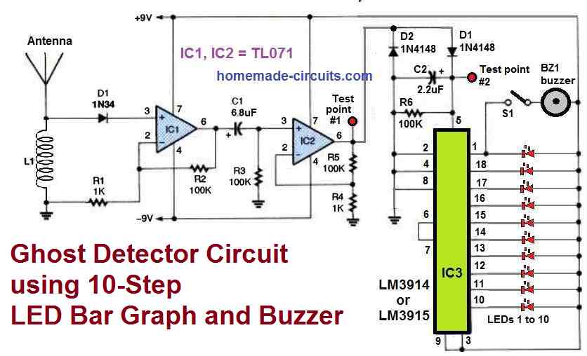
As shown above, this new ghost detector circuit using 10 step LED bar graph will measure the existence of a paranormal activity more accurately than any of the other circuits ever built.
It is hugely sensitive and can detect the presence of the smallest level of paranormal occupancy.
For low level vibrations, only a few LEDs will light up. However, more number of LEDs will start illuminating as the paranormal detection becomes stronger and stronger.
If the infestation is too high, you may find all the 10 LEDs illuminating along with the buzzer beeping....time to leave the area ASAP.
Making the Sensing Coil L1
The detector coil L1 is built by winding 100 turns of 30 SWG super enameled copper wire over a 1/2 inch ferrite rod.
The antenna can be simply a 6 inches flexible wire.
The test points 1 and 2 can be used to check the voltage levels using a digital multimeter or can be hooked up with an oscilloscope to analyze the paranormal waveforms.
Using IC LM324
A single versatile IC 324 is involved in the whole operation.
The IC is a quad opamp IC, meaning four opamps in one package.
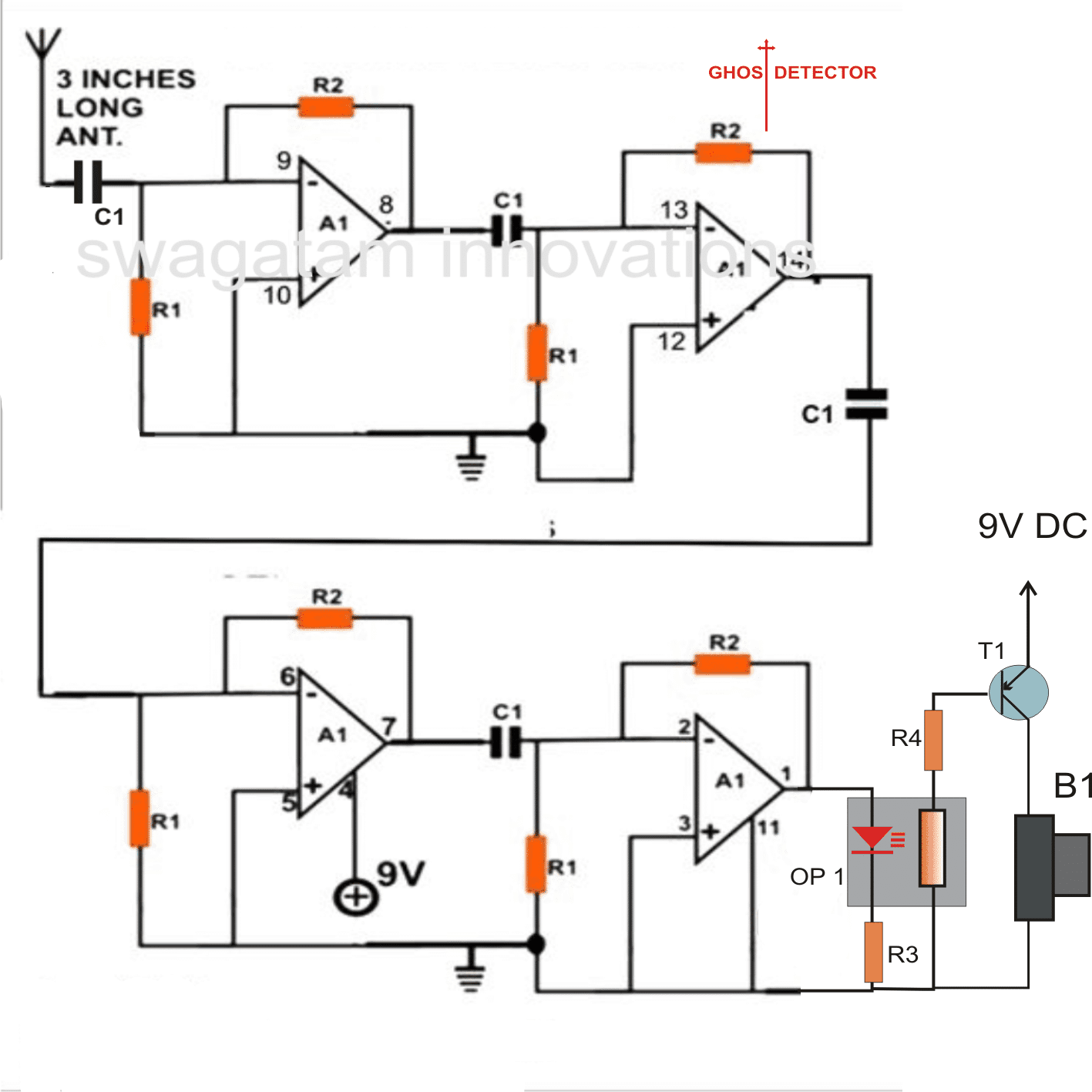
Referring to the figure, the opamps can be seen configured as hi gain non inverting amplifiers.
All the opamps are configured as high gain signal amplifiers.
Tiny electromagnetic or RF disturbances which are typically found being generated during the presence of ghosts or paranormal activities are instantly picked up by the antenna of the circuit and are fed to the input of the first opamp stage at pin #9.
The signals get instantly amplified and are transferred to the subsequent stages for further amplification and enhancement.
The output of the last opamp is connected to an opto-coupler.
The optocoupler is a homemade type, incorporating an LED and an LDR fixed such that their emitting and detecting surfaces are placed face to face inside a light proof enclosure.
Here, the optocoupler is used for sensing the LED illumination that may occur when a certain paranormal activity is sensed.
The illumination produced over the LED is tracked by the LDR whose resistance falls with the LED light.
The fall in the resistance of the LDR activates the connected transistor at the output, which in turn actuates a buzzer or a horn indicating a possible ghost intrusion.
The whole circuit may be built over a small piece of vero-board and should be strictly operated with a 9 volt battery.
The whole system may be enclosed inside a plastic box with the antenna kept protruding out of the box.
Parts List
- R1 = 100K,
- R2 = 2M2,
- R3, R4 = 1K,
- C1 = 0.01uF ceramic
- OP1 = LED/LDR assembly inside a light proof enclosure,
- T1 = BC557,
- B1 = Piezo Electric Buzzer
The above circuit was further modified by one of the enthusiasts Mr.Steven Chiverton, I have explained more regarding the procedures from
Improved Ghost Detector Circuit
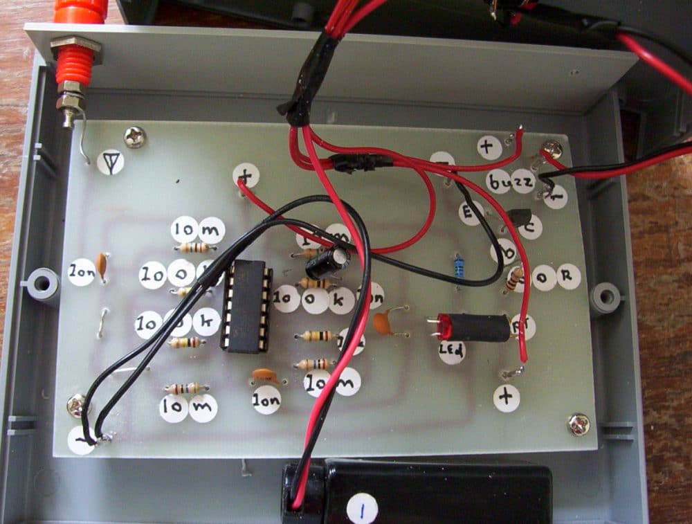
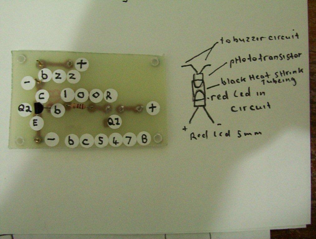
The circuit board i made a bit longer and included the ghost detector and at the end i did the circuit you submitted and made sure the photo transistor was opposite to the ghost detectors led one picture is your transistor buzzer circuit i made it separately to test then added it to the printed circuit board with the ghost detector on it.
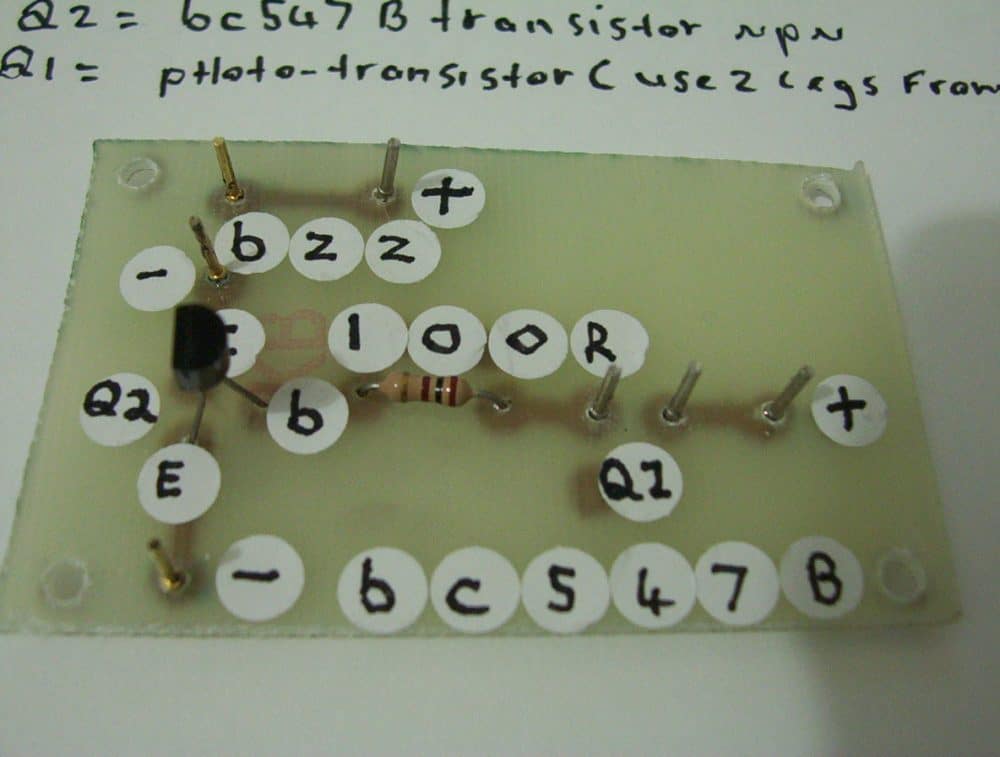
Here is another picture of your optocoupler buzzer circuit for the ghost detector,
i used matrix pins on the board like i do with many circuits.this eliminates the job of having to take the board out of the circuit to resolder wires , buzz wires go to buzzer and q1 wires go to phototransistor, and the positive and negatives go to switch that runs to 9 volts battery to positive buzzer to positive in and negative of buzzer marked with the minus symbol.
Hi Steven,
You have made this small circuit very special and all the effort you have put is amazing.
Thanks once again,
Swag
Thank you swagatam
It's your circuit your ideas I've upgraded thank you , now we have also the most sensitive lightening bolt detector for its size well have to test it out on a lightening bolt yet even though its very sensitive to the continuous sparking of the electric ignitor on the gas stove here it sounds awesome like receiving pulse rays well you should hear it different from just a hand held gas stove lighter with peizo electric sparks .
Ghost Detector Using Transistors
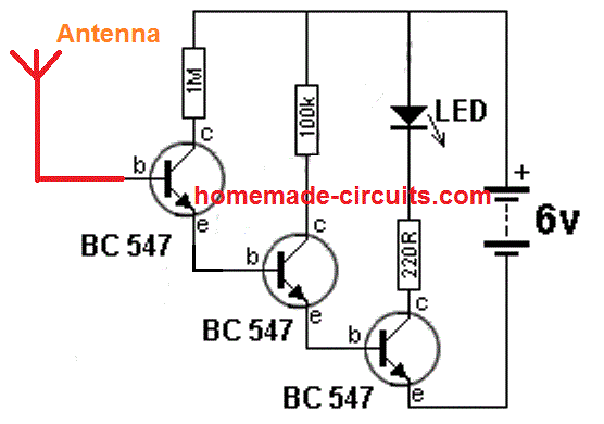
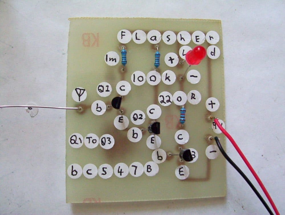
Here is the talking electronics 6 million gain circuit it may be a good ghost detector circuit to and by changing the bc547 to the bc517 you get a 30 million gain circuit as featured on youtube as a spirit detector but I haven't found any ghosts yet to test it on.
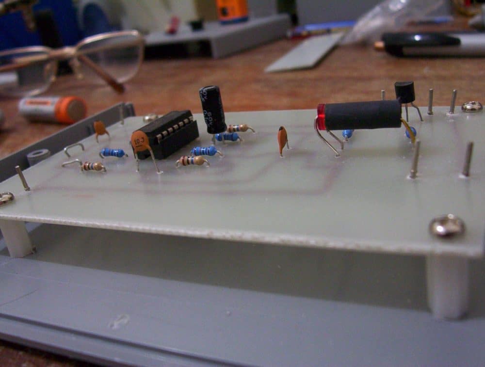
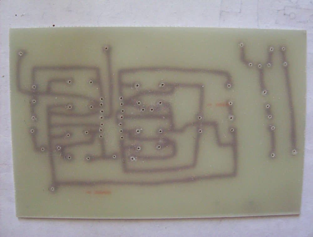
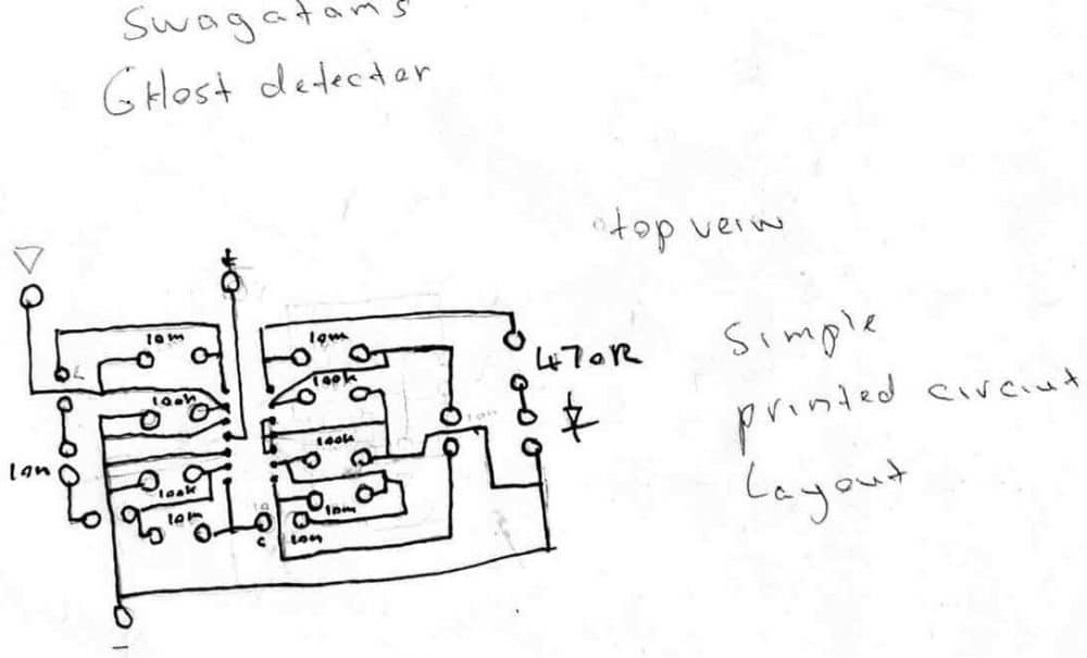
010jpg is the top view of the printed circuit board for the swagatam ghost detector circuit. 006 jpg is a close up of another ghost detector i just made notice the home made optocoupler using the fairchild photo transistor and led at each ends of a short length of black heatsink tubing.
ive changed the 10n ceramics to 10p to see what results i get when ive completed it allcouldn't resist the temptation to build another of your ghost detector circuits, so ill have backup in the case one fails
i hope you find some of these pictures better for your site or collection, this ones half finished so i have to do the wiring then put the rest of the box together as its a 3 peace one and maybe put the buzzer this time in a different area , etc etc i plan to build your ac sensor next to when i get to it ill email you all the details when i get to that one
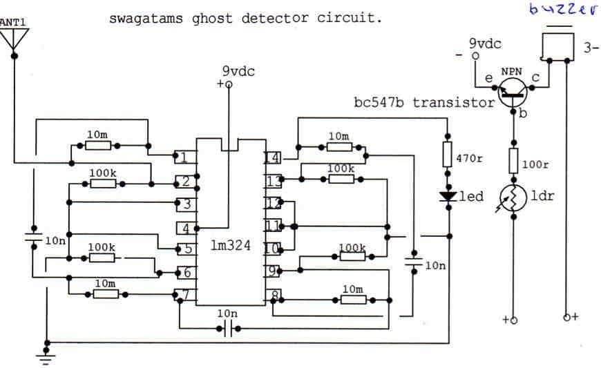
This is how i redraw circuits in a more simpler way using student version circuit maker , note the ic shape in its proper rectangle configuration , drawn using the trax maker tool and the pins stretched into there sizes, and shaped properly using the arrow tool, the numbering for the pins was done 1 number at a time using text tool function then dragged into the positions using the arrow in the program
READERS ARE REQUESTED TO SHARE THEIR EXPERIENCES WITH THIS DEVICE. A PHOTO OR A VIDEO PROOF WILL BE GREATLY APPRECIATED....


Questions & Answers
How can this circuit be improvised so that it detects the RF in the range 2.4-2.5GHz?
the above circuit will not detect any signal as long as it's not strong enough….cell phone signals in air are not strong and needs to be amplified….. therefore the above circuit cannot be used for detecting 2GHz cell phone signals from the local netwrks
Thanks for this Circuit, Can i Add both the circuits in series to make it more sensitive and add led meter such as lm3915, if yes please suggest what to modify and add.
yes you can try that, should work, however, too much sensitivity would also mean the circuit getting prone to other RF signals from electric towers, mobile phones, etc.
where is to connect negative terminal of battery..
the line which carries the "earthing" symbol
Can you convert it to visual warning (like led), instead of audio warning (like buzzer). If yes, what components should I add/remove. thanks…
Remove the entire buzzer section along with the opto and simply connect an LED in series with R3….
Circuit is ok but buzzer is ringing when connected to source…help me out.
connect a 3V zener in series with the buzzer
I have done this circuit completely but nothing is working….i think it is fake…?
don't blame the circuit just because you are incompetent
Dearest Swagatam,
I am surprised to have found this circuit in your collection.
If I wanted to measure the intensity of the signal, could I eliminate the optocoupler and buzzer, and instead replace it with a voltage divider that would allow me to read out the voltage with an arduino and a digital display?
–All My Best,
–Tom
Dearest Patricia,
I am glad you liked my site….
yes you can try that… it might work.
… actually, adding your voltage indicator circuit, here: https://www.homemade-circuits.com/2013/06/3-step-dc-voltage-level-monitor.html would be ideal…
yes it would be good, you can add an integrator (a network of resistors and capacitors) at the output of the "ghost detector" circuit to get a better response.
Hello, I’ve set up and it works very well, I’d like to know if it’s possible to set a dimmer potentiometer and increase the sensitivity when you need it, thank you. email : waguinhoestudio@hotmail.com
Glad it’s working, thank you for updating. You can replace the 2M2 resistors with a 2M potentiometers to get a variable gain facility.
Sayın Swatagam . Öncelikle projelerinizle insanlığa vermiş olduğunuz çok değerli hizmetleriniz için çok teşekkür ederim . Uzun bir süredir çalışmalarınızı takip ediyorum. Takip ettiklerim arasında çalışmalarınızla zirve yaptığınızı düşünüyorum. Diagramlarınız stil olarak çok güzel ve anlaşılır. Daha iyisini düşünemiyorum . Bu itibarla Sağlık, başarı ve mutluluklar diliyorum
Çok teşekkür ederim Bilal, işimi sevdiğine sevindim ve düşüncelerini takdir ediyorum. Evde kalın ve güvende kalın. Kendine iyi bak ve Tanrı seni korusun!
I’m also An Electronic Engineer and a software Engineer.
I test all of my circuits using Tine Industrial as it is the best I have found for this type of circuits.
I also write firmware for micro-controllers and FPGA.
If anybody needs anything tested out just shoot me an email at: URDUNN4.1010 (at) gmail.com
My name is Robert by the way.
Ok. I wired in the circuit above. Turned on the switch and the buzzer turns on. I was thinking this is a circuit that the buzzer goes off only when something comes close or touches the antenna? Am i missing something?
Did you use battery as the Dc source? You can try using two op amps instead of 4, and check the response!
Yes, 9v battery as the source. I’ll try and use just 2 opamp and see what happens. I’m going to have to double check the wiring. Cause even leaving the antenna off, the buzzer goes off
Sure, thanks for updating!
The LDR, does it take a certain led, like IR. Or will any color led work?
Any ordinary colored LED will work. I would recommend testing the circuit with an LED only and then try with the opto coupler. Another similar circuit can be studied in the following article:
Anti Spy RF Detector Circuit – Wireless Bug Detector
I did hook it up with a regular led before the coupler and it did the same thing. Even pulled the ldr out and the buzzer still goes off when i turn on the switch. Something isn’t right
Something might be wrong in that case….because my prototype was thoroughly tested, and it worked quite well..
Where did you connected that 0.1uf 50v capacitor ?
There’s no 0.1uF capacitor in any of the circuits!
Close to pin 8 and 10m resistor black color capacitor im not sure about value as its not clear in photo but its there
Do you mean C1…it is 0.01uF not 0.1uF
It’s 103 pf I think
Yes that’s correct!
Hey sir should I use 2m resistor at place of 10m ?
You can try 2M also initially…10M will increase the sensitivity a lot.
Can I add a buzzer in first circuit given to @Endless a colourful Image that is LM 324 IC ,2.2 m (R),100k (R),104pf,& l.E.D(1)
If yes please say connection of the Buzzer in said circuit.
The connection of the buzzer i shown in the first circuit. You can see an LED and LDR tightly packed inside a lightproof enclosure, and a BC557 transistor T1 is attached to the LDR with a buzzer.
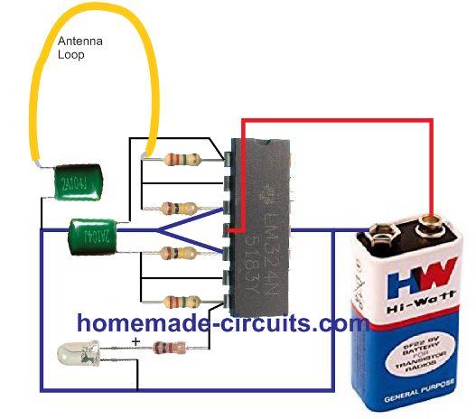
If the circuit looks difficult to you, you can try the following circuit:
The capacitors are 0.1uF PPC type.
You can replace the LED with a piezo buzzer
Please tell me which of these two circuits is more powerful, I want to make it? Is the one with transistor better or the one with IC?
The one with the IC is the more powerful one. However it is too sensitive and get disturbed with other atmospheric noises. I would recommend to you try the following circuit instead:
Parts List
capacitors = 0.1uF/100V
Resistors = 2M2 2nos, 100K 2nos, 1K 1no.
IC is LM324
You can also try the following circuit for an advanced 10 LED indication.
In the first drawing of the 10 led bar graph (New Update) I am having trouble finding a 6.8 uf capacitor listed in any of the available capacitor kits. Is there another one that will work in it’s place without sacrificing sensitivity?
The capacitor value is not critical. You can try any capacitor between 2.2uF and 10uF
I am messaging you for a important discussion about Spirit Box..
Many year’s ago Sir. Nicole Tesla described about white noises.
He said at that time 1N34 and related germanium diode’s are much sensitive to sense Entity’s Communication with Human’s by Radio..
I have a Ham radio’s L board..with IC chip 1895 and few transistors.
Today ,this 1895 I.C L boards and 6/7 transistors L boards present in market very small amount..But those boards are Stronger Signal Catcher with 1N34/1N34A/OA79 diode’s…
But unfortunately 5 pin gang which Select manually channels are missing in the market in India.. which is used in AM/MW/SW radio’s..
Radio is the main medium to communicate with Entity’s.AM(Amplitude modulation)
Instead of Gang capacitor which component I use to track that channel’s which select channel’s automatically ghostly White noises ..
I will say Automatically channel Selector/Automatic frequency Control.
Previously Sir Nicole Tesla and Thomas Alva Edison have described about…
I need your help…
Thank you..
Ranabir Bhattacharya..
Thank you Ranbir, I appreciate the valuable information that you have shared.
However, without a GANG condenser it is not possible to change radio stations, and there’s no direct replacement to GANG devices.
Instead of using a radio, you can use special white noise generators to detect ghosts.
I have an article on white noise generators which you can read here:
https://www.homemade-circuits.com/white-noise-and-pink-noise-generator-circuit/
Hello. This ghost detection device that you made with three transistors and took a photo of, its circuit is correct, but you have connected the bases of the transistors wrongly and this device does not work. You have to reverse the transistors and change their left and right bases together. Thank you
Hello, Thanks, you are correct, in the prototype image of the assembled PCB the emitter and collector leads must be reversed. By the way it was not built by me, it was built by one of my friends Mr. Steven. Maybe he might have realized later and corrected his connections.
top diagram what led can handle the 9v input
20 mA 5mm. I would recommend using 5V or 6V instead of 9 V.
Sir, I want the the voltage ratings of the top diagram ghost detection circuit using TL071 and LM3914 capacitors mainly 6.8üf and 2.2üf
Hi Spandan, The voltage ratings of the capacitors are all 25V.
Can I use 6.8üf 50v and 2.2üf 160v…… because at the moment I only have these….
Yes, sure, having higher voltage ratings does not matter…
Okay sir, thank you????.
You are welcome Spandan…
I have one more question sir, those LEDs in the top circuit is connected directly to the 9v supply to LM3914 pins……does LM3914 has internal resistance in series to safely lower the current for the LEDs to function….or else they might burn up due to excessive current.
Yes, the IC has internal resistors across its output pins, just make sure that the input dC is not above 9V so that the IC can remain cooler.
Sir, I made the top circuit but as soon as I turn it on all the LEDs lights up and remains ON.
Spandan, Remove the antenna completely and check again. Also check the voltage at Test point#1, and let me know.
Sir the Voltage is 9.63 V between the test points, after removing the antenna.
This circuit needs a dual supply for supplying +9V and -9V for the op amps. Are you using a dual supply. And this can be implemented using two 9V batteries in series.
Two 9v in series will correspond to 18v …. I was using only one 9v battery before and now using two. Still there is no difference sir , the LEDs are lighting up as soon as I turn the circuit on….also I missed a point before, I am not using TL071 because it’s unavailable to me , instead I am using F4558 ic which has dual op amp in one package and I was only using one of its op amp and then cascading it to the second F4558 ic.
You will have to use two 9V batteries in series (18V) for supplying the op amps and use the series center connection of the batteries to the line indicated by the Ground symbol. Without the dual supply the circuit might not work.
The opamp variant might also be crucial since this is a very sensitive configuration.
This circuit was taken from a popular old magazine so the circuit cannot be wrong.
If you want a single battery circuit, then you can try the following concept….I will explain you how to integrate with LM3525 later, once you have successfully built it.
https://www.homemade-circuits.com/bug-detector-circuit-rf-sniffer-circuit/
Sir, could you provide me a simplified version of the 10 LED Bar graph ghost Detector circuit…
Spandan, Please first build a single LED ghost detector circuit successfully, then you can integrate it with a 10 LED circuit.

First build the following design successfully, then I will tell you how to integrate it with the 10 LED circuit:
The capacitors are 0.1uF/100V
The top most resistor is 2.2 M
middle two are 100K
the 4rth one is again 2.2 M
The LED resistor is 1K
Okay Sir.
saludos.vi tu circuito en youtu, lo usan para detectar iones como detectores de oro.el segundo circuito con lm324 funciona igual y como probarlo. puse resistencias de 10 megas .te felicito muy buena tu pagina.
Thank you Normath,

I think you should try the following circuit. Here the connections are easier to understand. Don’t use 10m for feedback, 2.2m is sufficient, higher values will make it too sensitive.
हैलो सर मुझे इस घोस्ट डिटेक्टर में रूचि है पर इसको बनाने में मुझे ज्यादा नॉलेज नहीं है, मुझे इसका वीडियो मिल जाता तो शायद मेरे लिए बहुत सहायक होता?
Hi Rakesh,

You can try this simple version, it is not so difficult:
The IC is LM324
Capacitors are 0.1uF PPC.
क्या यह बेहतरीन काम करेगा?
Yes, it will work perfectly and it will possibly detect paranormal activities (in haunted areas), provided there are no other RF interferences such as AC high tension wires, mobile phone calling, or thunder storms.
Thank you sir.
sir circuit sahi banane ke baad bhi light band nahi ho rahi hai
The LED should remain OFF when no RF is available in the atmosphere. I have tested this circuit, you can check the video here:
https://www.youtube.com/watch?v=u-_mEOF5NEA
ready ho gaya sir thanks.
That’s great Rakesh! Let me know if you have any further questions…
9 volt ki battery garam hoke discharge ho gai
It means your circuit, or the IC has problems…

Parts List
100k – 2
2.2 meg – 2
1k – 1
0.1uF capacitors – 2
IC LM324 – 1.
isme Buzzer ka upyog kaise karu
You can replace the LED with a DC buzzer.