The circuit identifies and detects the temperature difference between two sensors and activates a relay when the temperature is not identical on these differently positioned sensors.
By: Manisha Patel
It'll also enable you to detect a difference in temperature, although the temperature sensing devices can be set are discretely, using a potentiometer.
Operational Details
To implement the sensing abilities a couple of ordinary "garden" diodes are used as temperature sensors (D1 and D2).
As the anodes of both the diodes are attached with the inputs of an opamp it works like a comparator, configured to detect any temperature difference to cause it to output a low voltage.
These diodes should be positioned over two distant desired locations across which the temperatures may be required to be compared. The sensors are capable of detecting even the slightest amount temperature variation across each other.
- If the diode D1 is placed in a questionable place where the temperature relatively decreases, the opamp gives an output low and activates the relay through the via the transistor Q1. The transistor may be used to activate a heating system or similar with an intention of restoring the decrease in the temperature..
- Identically if the diode D2 is positioned across a susceptible premise to sense an increase in temperature, the opamp gives an output low again activating the relay through the transistor Q1. In this application the transistor/relay may be employed for activating a cooler system or a fan.
In an event when the temperature of the two diodes are restored to equal temperatures, the relay is deactivated.
It must be noted that the inclusion of the potentiometer is to vary the sensing levels of the circuit as per the user preference.
Note: The circuit can be powered by 9V battery. The relay should also be rated at the same voltage as the supply.
Circuit Diagram
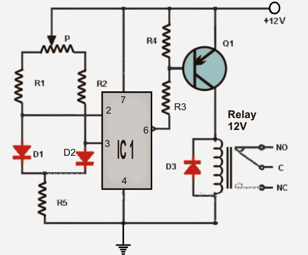
List of components for the above differential temperature detector circuit:
- IC1: operational amplifier 741.
- Q1: PNP BC557
- R1 = R2: 4.7K
- R3 = R4: 1.2K
- R5: 2.7K
- P: 100K pot
- D1 = D2 = D3: diode 1N4001
- RL1: 12V relay.

Questions & Answers
Dear Swagatam,
First of all wish you a very happy new year 2021.
We made the above temperature controller circuit. But unfortunately it is not sensing the temperature with diode D1 and D2. The question is, how a diode can work as temperature sensor?
Should we use some temperature sensor, instead of diode D1 and D2?
Thank you Dear Prakash, and wish you too a Happy 2021.
This design was submitted to me by an eternal author, but it seems the circuit should work.
All semiconductors respond to temperature changes by altering their forward voltage drop.
A 1N4148 diode will likewise will show a reduction in its forward voltage by 2 mV in response to every 1 degree rise its body temperature. Meaning, its normal 0.6V forward drop will keep reducing by 2mV for each degree rise in temperature.
What component used to detect temperature difference in this circuit
D1 and d2
1N4007 can be used?
yes can be used