In this article I have explained how to design your own customized, simple LED driver circuits at home. We will learn how to calculate specific LED configurations for applying the LEDs with appropriate LED driver power supplies. In these driver power supplies I have explained two concepts one by using SMPS boards and the other by using capacitive power supplies.
What is an LED Driver
An LED driver is an electronic circuit specially designed to drive or illuminate a set of LEDs safely through controlled current and voltage output, as per the specifications of the LEDs.
Since LEDs are vulnerable semiconductors devices, they must be driven using a regulated current and voltage power supply. Thus, we can also say that LED drivers are basically power supplies, specially designed to operate or illuminate LEDs through controlled parameters, so that the LEDs illuminate optimally without the risk of an over voltage or an over current.
This implies that an LED driver must feature a constant voltage and a constant current, ensuring that the LEDs are never subjected to abnormal voltage or current conditions, and they never burn or deteriorate overtime.
The biggest enemy of LED is overheating, which can cause a thermal runaway situation in LEDs. Overheating may be caused due to over current or over voltage, and this is exactly why these two parameters must be strictly regulated in any given LED driver circuit.
LED Parameters
Before we start learning LED driver circuits, it would be important to understand a few of the LED specifications which are crucial to designing drivers for them. These are, LED forward voltage rating or the VF rating, and LED forward current rating or the IF rating.
LED Forward Voltage Rating (VF): It is basically an optimal voltage rating of the LED which is supposed to be supplied by the driver or the power supply to illuminate the LED with optimal brightness. This voltage must never be increased to ensure proper safety to the LED.
LED Forward Current Rating (IF): It is the maximum operating current of the LED, exceeding which can cause a deterioration or even permanent damage to the LED.
For example a standard 1 watt LED has a forward voltage rating of 3.3 V, and a forward current of 0.303 Ampere. Exceeding the forward voltage of 3.3 V can cause an increase in the current consumption exceeding its maximum tolerable IF rating of 0.303 amps. This may result in overheating of the LED so that it ultimately burns and gets permanently damaged.
The forward current can be calculated by dividing the LED wattage by its forward voltage. For the above example, this is IF = 1 / 3.3 = 0.303 Amps
While designing an LED driver it must be ensured that it provides the LEDs with the correct amount of VF and the IF parameters, so that that the LEDs are able to illuminate optimally without any risks of damage.
Now we will see how the VF and IF parameters, as explained above, can be correctly implemented using the right LED configuration and by calculating the LED resistor correctly.
LED Configuration
While designing LED drivers the LED configuration must be correctly matched with the voltage output of the driver, such that the driver voltage is equal to the forward voltage spec of the LED configuration.
This ensures that the correct amount of forward current passes through the LEDs. However it is always not possible to match the driver output with the available LED configuration.
In case the driver output does not exactly match with the forward voltage spec of the LED then we use series current limiting resistor to adjust the voltage and current of the driver with the LED.
Example#1
For example, let's say, the output voltage of the driver is 12 V DC (with 1 Amp current), and we want to connect a 3 watt LED with this DC output. Assume we have 3nos of 1 watt LEDs with forward voltage specification of 3.3 V each.
We want the forward voltage of the LEDs to match as closely as possible with the 12 V spec of the driver.
Therefore we add the 3 LEDs in series, so that the total forward voltage of the LED string becomes 3.3 + 3.3 + 3.3 = 9.9 V. This is close to 12 V but still not precisely equal.
If we connect this 3 LED string directly with the 12 V supply of the driver, that would cause each LED to be subjected to a forward voltage of 12 / 3 = 4 V. This looks too high for each of the LEDs, and this would instantly burn the entire 3 LED string.
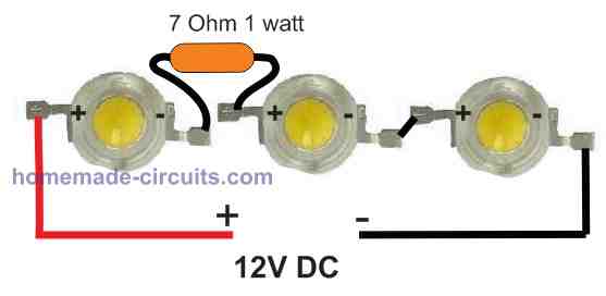
To prevent the above issue, and to ensure that the 3 LED string works correctly with the 12 V from the driver, we add a series resistor with the LED string. The resistor value is calculated by considering the total forward voltage of the LED string, the maximum current spec of the LED string, and the supply input voltage from the driver.
R = Supply Voltage - Total LED forward Voltage / LED Current.
R = 12 - 9.9 / 0.303 (All the 3 LEDs will have 0.303 amp current since they are connected in series.)
R = 6.93 Ohms or 7 Ohms.
Therefore, we would need a 7 Ohm series resistor to ensure that 12 V can be safely used with the 3 LED string.
The wattage of the resistor can be calculated using the formula:
W = (Supply Voltage - Total LED forward Voltage) x LED Current.
W = (12 - 9.9) x 0.303 = 0.63 watts, or simply a 1 watt will do.
Example#2
Let's consider another scenario where we want to configure a 6 watt LED to a 12 V, 1 Amp driver output. Assuming we have 6 nos of 1 watt LEDs, we want to make sure that the total forward voltage of the LEDs is as close as possible to the 12 V DC output.
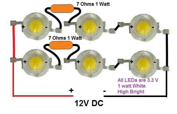
Just as the previous example, putting 3 LEDs in series provides a total forward voltage of 3.3 + 3.3 + 3.3 = 9.9 V. Since we have 6 LEDs, means we have to create two such strings having 3 series LEDs on each string.
Once the two strings are created, the next step is to calculate the current limiting resistor for the two LED strings. As calculated in the previous example, we have to connect a 7 ohm 1 watt resistor in series with each of the two LED strings, and then simply join the two LED strings in parallel.
This parallel combination then finally could be attached to the 12 V supply for getting a matching configuration with the supply.
Example#3
In the above two examples the calculations were pretty easy since the LED numbers were even. Now let's consider an LED combination which is not even.
Let's imagine we want to connect a 7 watt LED to the driver's 12 V supply.
Let's assume we have 7 nos of 1 watt LEDs for the 7 watt LED configuration.
We implement the same procedures as above.
We first create two strings of LEDs having 3nos of 1 watt LEDs each, along with a 7 ohm 1 watt series resistor on the each of the strings.
We connect the above two strings in parallel, as before.
For the above configuration we use 6 LEDs , and find that we have still have one LED left with us, which also needs to be included in the design.
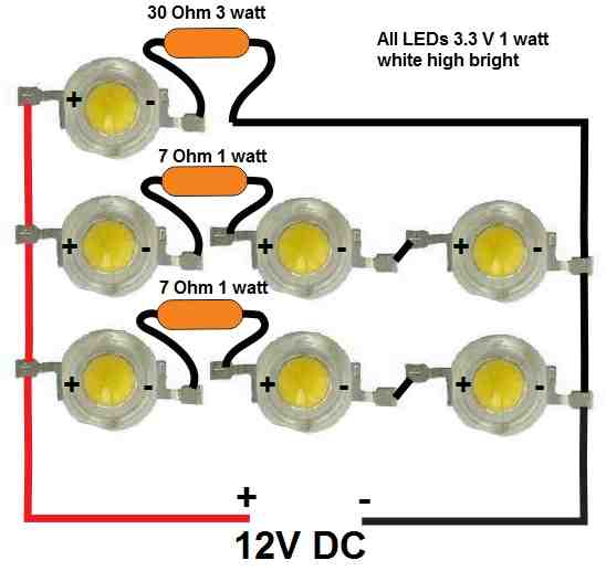
We have no other option but to connect this single LED parallel to the two strings.
However, this single LED will also need a resistor so that its 3.3 V forward voltage could be matched with the 12 V supply.
We use the same formula as above to calculate the limiting resistor for this single LED string:
R = Supply Voltage - Total LED forward Voltage / LED Current.
R = 12 - 3.3 / 0.303 = 28 .71 Ohms, or simply a 30 Ohm will do.
Wattage = 12 - 3.3 x 0.303 = 2.63 watts or simply a 3 watt will do.
Using the above methods, it is possible to configure any number of LEDs in series/parallel combination to suit any specific power supply output.
Now coming back to our LED driver subject, in this post I will elucidate two simple methods of designing LED drivers, 1) SMPS method, 2) capacitive power supply method.
Warning: Circuits I have explained below are not isolated from mains AC, and therefore are extremely dangerous to touch in the powered and open condition. You should be extremely careful while building and testing these circuits, and make sure to take the necessary safety precautions. The author cannot be held responsible for any mishap due to any negligence by the user.
SMPS LED Drivers
SMPS LED drivers are built using SMPS technology or switch mode power supply technology, which are by far the most efficient type of power supplies due to their low dissipation and reduced wastage of power.
However, designing SMPS power supplies is not easy and requires a lot of calculations, so new hobbyists can find this aspect of an SMPS undesirable, and inefficient.
Therefore it may seem that designing SMPS LED drivers can be indeed a complex affair, and most electronic enthusiasts or professionals may find this not so preferable.
That said, there is an easy workaround through which cheap and quick SMPS LED drivers could be created.
It is by procuring ready-made, cheap SMPS power supplies from the market, and then configuring an LED stage at its output, through a current control circuit.
A cheap 12 V 1 amp SMPS board example can be seen in the following image:
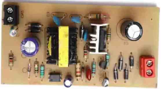
These modules will produce 12 V DC 1 amp output, with a capacity of 12 watts. We can easily attach appropriately configured LEDs strings at the output through a current controller stage for converting these SMPS boards into easy and safe LED drivers.
Why do we Need a Current Controller Stage
We need a current controller to ensure that the current to the LEDs does not increase above the tolerable limit of the LED specifications.
A current controller becomes essential only for high wattage or high current LEDs, typically for LEDs that have a current specifications of above 100 mA.
For low current LEDs below 100 mA a current controller stage may not be necessary, and the current can be controlled simply through a calculated series resistor.
You may be wondering why a current controller may be needed for high a watt LED, despite of having current limiting resistor attached in series with the LEDs?
It is because of the significant amount of heat generated by the high watt LEDs. Low wattage or low current LEDs do not emit too much heat and therefore the series resistor becomes sufficient for controlling the current.
In high watt or high current LEDs, despite of a series resistor there's a very high amount of heat generated which causes the current draw of the LED to increase proportionately. This in turn causes more heat to be generated, and more current draw.
The situation finally becomes uncontrollable causing the LED to eventually burn. This is known as thermal runaway situation, and is commonly seen in power transistors also.
A current controller stage ensures that the current draw by the LED can never increase beyond a set limit. This limit is usually the highest tolerable current specification of the LED.
Along with a current controller stage, we also need the high watt LED to be mounted over a heatsink to ensure that its temperature never becomes too high, which may otherwise cause the life of the LED to deteriorate.
Simple 6 Watt SMPS LED Driver Circuit
The following design depicts a simple 6 watt driver example using a cheap commercial SMPS board.
Simply by adding a current controller stage between the SMPS and the LEDs, we transform the SMPS circuit into a fully compatible LED driver module for the 6 watt LEDs.
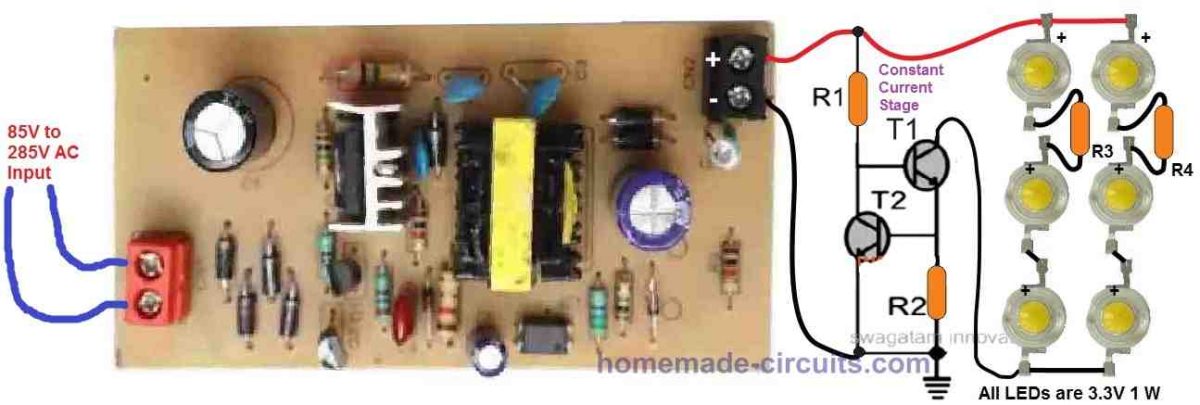
Parts List
T1 = TIP122
T2 = 2N2222
R1 can be calculated using the following formula:
R1 = (Supply Voltage - BJT forward base voltage) BJT HFe / Collector load Current
= (12 - 0.6) 1000 / (0.303 x 2) = 18811 = 18 K approximately.
So R1 = 18 K
Wattage = P = V2 / R = 122 / 18811 = 0.0076 watts. This means a 1/4 watt resistor will be sufficient.
R2 = 0.6 / Max Constant Current = 0.6 / 0.606 = 0.99 Ohms, or a 1 Ohms will work fine.
Wattage = 0.6 x Max Constant Current = 0.6 x 0.606 = 0.36 watts, or a 1/2 watt will do the job nicely.
R3, and R4 are already calculated previously in Example#2 above.
12 watt SMPS LED driver Circuit
Using the same steps a explained above, a 12 watt LED could be designed as shown in the following schematic:
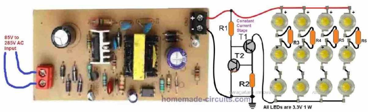
The resistors can be calculated in the same way as done for the previous 6 watt example. The current control transistors will remain the same since TIP122 can handle well above 1 amps.
Since the indicated SMPS board has a maximum specifications of 12 watts ( 12 V x 1 A), a maximum of 12 watt LED can be configured at its output. For applying higher watt LEDs the SMPS module might need to be upgraded accordingly.
The above examples shows us how any ready made standard SMPS board procured from the market can be easily converted into a full fledged working LED driver by appropriately configuring the LED circuit along with a transistorized current control stage.
However, for those who do not wish to use ready made SMPS boards, rather want to build the entire SMPS circuit discretely can follow the following links and try the designs provided therein.
2 Compact 12V 2 Amp SMPS Circuit for LED Driver
7 Watt LED Driver SMPS Circuit – Current Controlled
Make this 3.3V, 5V, 9V SMPS Circuit
32V, 3 Amp LED Driver SMPS Circuit
SMPS 50 watt LED Street Light Driver Circuit
12V, 24V, 1 Amp MOSFET SMPS Circuit
5V, 12V Buck Converter Circuit SMPS 220V
Cheapest SMPS Circuit Using MJE13005
Capacitive LED Driver
A capacitive LED driver can be built through a capacitive power supply, which is also popularly known as transformerless power supply.
It consists of a high voltage capacitor connected in series with one of the input mains terminals for limiting the current to the desired lower levels, depending on the rating and the configuration of the LEDs.
The stepped down AC is rectified using a bridge rectifier, and a filter capacitor, just as we do with any other standard AC to DC power supply circuit.
However there are a couple of serious issues with capacitive power supplies.
- Although the current is limited, the output of a capacitive power supply always produces the peak levels of the AC RMS. Meaning, if the input is 220 V AC, then the output DC from the capacitive power supply will be 310 V DC.
- Whenever capacitive power supply is switched ON, a high surge current is generated at the output which can instantly fry any LED connected at its output.
- The current from a capacitive LED driver has to be on the lower side, because higher current results in a proportionately higher surge current during power switch ON. Typically, the output current specs should be kept below 100 mA while designing capacitive LED driver circuits.
Adding Zener Diode to Control Voltage
The above two issues can be resolved by using appropriately rated zener diodes across the output of the power supply. But adding a zener also means unnecessary heat dissipation, and wastage of power.
Suppose we have an LED configuration whose total forward voltage is 24 V, then we may incorporate a zener diode to restrict the power supply output to 24 V, by using a 24 V zener diode.
However this would mean dropping the 310 V DC to 24 V DC which may result in a significant amount of power getting wasted through zener diode dissipation.
This simply means that there's no easy and efficient way to step down the output voltage from a capacitive power supply to lower levels. Therefore, it seems we do not have any other choice but to make use of the full 310 VDC from the power supply and configure the LEDs to match this 310 V DC.
To do this we first divide the 310 V with the forward voltage drop value of the LED.
310 / 3.3 = 93.93. Rounding it off gives us 94 numbers of LED for the configuration.
To allow some margin for a low voltage situation, we reduce the number to 90 LEDs approximately.
Calculating the Limiting Resistor
We use the same earlier formula for calculating the limiting resistor:
R = Supply Voltage - Total LED forward Voltage / LED Current.
R = 310 - (90 x 3.3) / 0.02 amps (Using 5 mm 20 mA LEDs for the configuration)
R = 650 Ohms
Wattage = 310 - 90 x 3.3 x 20 mA = 0.26 watts
To ensure better safety against switch ON surge currents, we can upgrade the resistor to a 1 watt wire wound resistor.
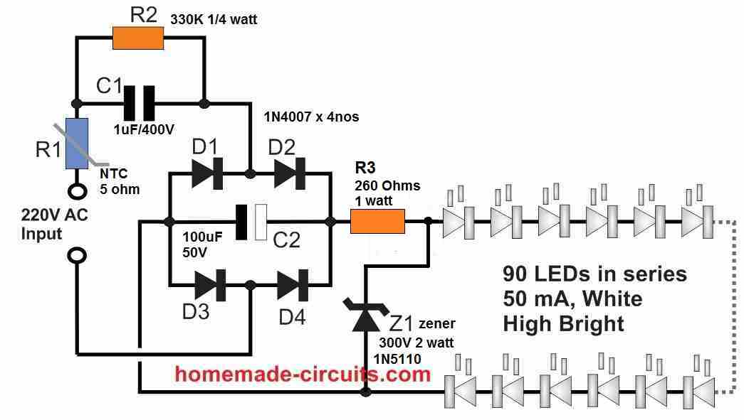
The final configuration would be like as shown in the following figure. A zener is added to guarantee increased protection against voltage fluctuations, and NTC ensures reinforced protection against switch ON surge current.
How it Works
In general, a 1uF/400V capacitor will generate 50 mA of current. So C1 here is 1uF/400V which can handle upto 50 mA load, with its 310V DC output.
Initially, the capacitor C1 is fully discharged and acts like a momentary short circuit, until it gets fully charged and stabilizes.
As soon as power is switched ON, the NTC controls the initial current surge, and after some milliseconds, the LEDs illuminate with full brightness. By this time C1 is already stabilized and the short circuit surge current is eliminated.
However, in a different scenario, if the NTC is unable to control the current surge, the zener diode switches ON at 300 V, which causes C1 to charge instantly and this stabilizes the current surge through it, safeguarding the LEDs and the zener diode.
From the above discussion we understand that for capacitive LED drivers, the ideal situation would be to use an LED configuration whose total forward voltage matches the peak output DC from the power supply.
However, if efficiency is not important, then other LED configurations with much lower forward voltage can be used, with appropriate zener diodes for controlling the peak DC from the capacitive power supply.
An example design can be seen in the following figure.
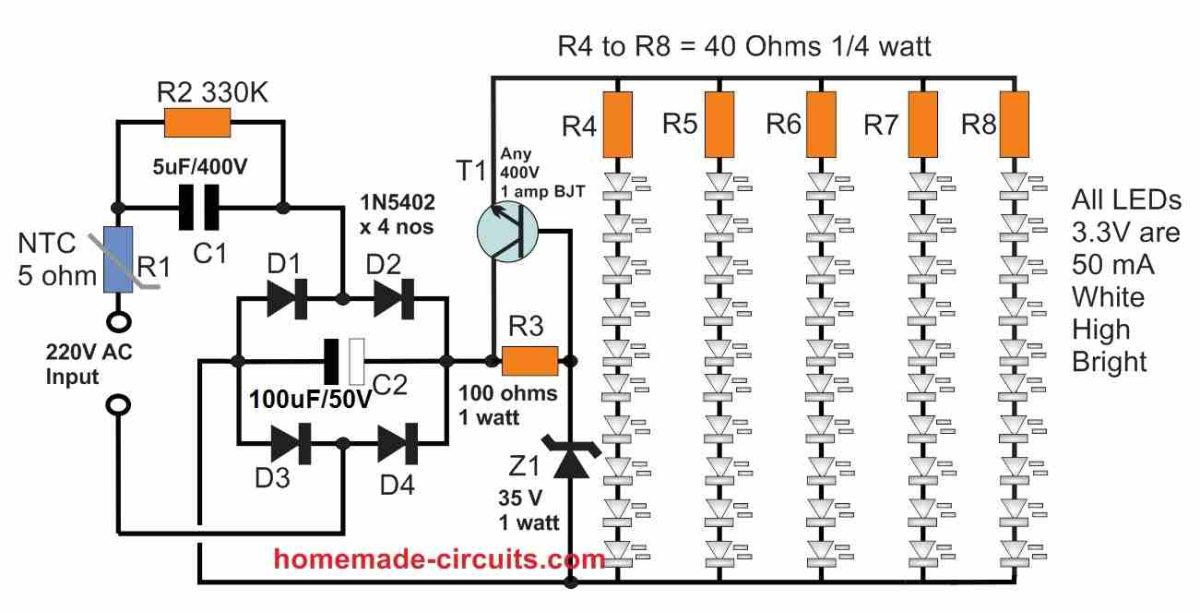
How it Works
In the above high capacitive LED driver circuit, we can see 5 parallel strings of LEDs each having 10nos of 50 mA LED hooked up in series.
This means the total consumption of the LED network is 50 x 5 = 250 ma.
As described previously, considering a 1 uF/400 V can produce 50 mA current, for getting 250 mA we will need C1 to be 5 uF/400 V.
However, a 5 uF/400V capacitor might also generate a substantial amount of switch ON current, which could easily destroy the LEDs, along with the zener diode.
Keeping this issue in mind we have introduced a transistorized voltage controller, which will keep the output voltage stabilized and in turn prevent an over current surge across the LEDs.
R3 will need to be experimented a bit to ensure that the transistor is able to deliver the required 250 mA to the LED strings.
Overall the above circuit looks good, however, it can be highly inefficient due to the high heat dissipation by the transistor.
Increasing the number of LEDs in the series strings will proportionately increase the efficiency of the circuit. However for this the series resistor, the transistor, the zener value all will need to be modified appropriately.
An Interesting way to Control Surge Current in Capacitive LED Driver Circuits
As discussed in the above paragraphs, the main issue with high current capacitive LED drivers is the switch ON surge current, which can instantly destroy the connected LEDs.
An easy way to suppress the above issue is by using a zener diode, however a zener diode being a semiconductor device itself may be prone to getting burned during a catastrophic switch ON voltage surge in a capacitive power supply.
A novel way to tackle this problem is by incorporating a mini low current relay, and switching the LEDs through the relay contacts.
This provides a couple of benefits to the overall design. First the relay coil absorbs all the initial switch ON current surge, and additionally it switches ON the LEDs with a slight delay further safeguarding from the initial surge current.
The complete schematic of the relay delay switch ON surge current protector for capacitive LED drivers can be seen in the following figure.
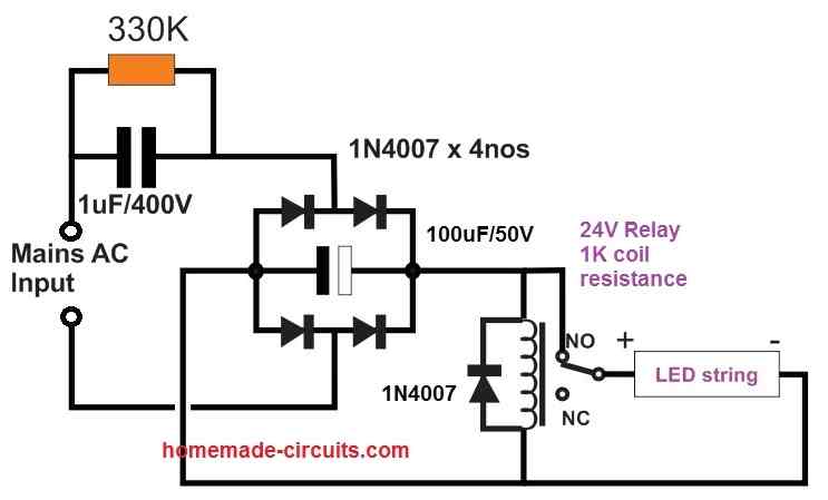
Make sure the relay is rated at a minimum of 24 V with coil resistance of 1K or higher. The 24 V mini SPDT or SPST type relays will work great in the above application.
Simple Zero Crossing Controlled Transformerless Surge Free LED Driver Circuit
As we know, even if the input capacitor is calculated optimally, switch ON current surge can become a major issue with capacitive transformerless LED driver circuits. Due to this LEDs often burn unpredictably. Although this can be eliminated using zener diode, a high current LED driver becomes possible only when a perfect zero crossing is implement, and without a zener diode.
The simple circuit diagram of a zero crossing assisted surge free transformerless LED driver is shown in the following diagram:
How it Works
Ok so here how this circuit works, and it’s actually very interesting if we try to look closely.
First we got this 10 uF capacitor right at the input side.
This one don’t just sit there, it actually does an important job.
It drops the incoming AC current down to around 500 mA.
After doing that, it pushes or feeds the full 220 V AC into the bridge rectifier stage.
Now what the bridge rectifier does is, it takes this low current 220 V AC and changes or converts it into a DC which comes out to be around 310 V.
This 310 V DC then goes straight into a special circuit made using a transistor and a zener diode which we can call the zero crossing controller.
So now as long as this DC voltage from the bridge rectifier stays above the zener diode voltage, what happens is, the left side transistor in the circuit stays switched ON.
And because it is ON, it connects the base of the right side transistor directly to ground, or we can say it short-circuits the base of that transistor.
So due to this grounding, the right transistor never gets a chance to turn ON, it remains fully shut OFF and because of that the output side of the circuit gets nothing, no voltage, zero.
That means even if the input side suddenly gets some high voltage surges or spikes from the AC line they don’t reach the output, they just get cut off fully by this action during those parts of the AC waveform.
But then something different happens when the AC voltage level drops and goes below the zener diode voltage which we can call ZX.
So at this point, the zener diode stops conducting or shuts off.
Because of this the left transistor also shuts off and when that happens, it no longer holds the right transistor's base to ground.
So now the right side transistor finally gets triggered ON.
Once the right transistor is ON, it starts conducting and it begins allowing the low voltage DC to flow into the LED strings connected across the output and also charges up the 1000 uF capacitor.
This big capacitor now stores or collects that voltage in it, like a tank.
Later on, this stored voltage from the 1000 uF capacitor is used for running or powering the connected LEDs in a safe and smooth way.
So the load only gets powered during those times when the AC voltage is below the zener value and that’s the key idea here.
This way, the zener diode and the transistor pair work together like a smart team and they make sure that the load only gets the voltage when it's within the safe, lower side of the AC cycle.
So the load never gets hit with sudden high voltage or high current spikes.
In this method, the load is always safe, it works nicely without any risk of getting damaged and the whole thing becomes reliable and clean.
Over to you
So what do you think about the above detailed description regarding simple LED driver circuits? Do you have any specific questions or any other simple LED driver design that you would like to share in this article? Please feel free to express your valuable thoughts and ideas through comments below.


Comments
Can you explain to me how the voltage changes automatically depending on the load in the inverter circuits operating the LED lights and thank you for your efforts my friend
Hi, can you please tell which circuit diagram are you referring to?
Normally, if the supply current is controlled, then the voltage will automatically adjust as per the LED total forward voltage level…
Dear sir
in past i am using attach link type circuit with instead of NTC i used 22E 2w fusible resistor. now days little issue of good quality make availability of 22E with fusible. i used 22E for current limiter.
may i used NTC of 5 to 10 ohms instead of 22E? Does it require MOV also in 220v line parallelly for safety of inrush & surge ?
My load current is 150ma @ 12v & it work with 22E fine in old days. So with NTC does it work safe?
https://www.homemade-circuits.com/wp-content/uploads/2025/06/capacitive-power-supply-12V-150mA.jpg
…No MOV is not required in this case..
Hi Nitesh,
yes, NTC is much better, because it alters and adjusts its resistance during power ON, and normal use, to ensure most efficient surge suppression and optimal output current. You can try 5 ohm or 10 ohm NTC. Also please add a 1N4007 as shown in my updated diagram…to minimize zener diode dissipation…
Dear
Can u explain little bit more how can 1N4007 control zener power dissipation?
u mean after apply 4007 max current pass thure it & zener becomes low heat & only regulate 12v? But when i fetch 12v @approx 150ma then it came out from zener cathode point . so i little bit not undestand
The diode isolates the zener diode from the filter capacitor, that means the zener diode now gets only the 100 Hz frequency from the bridge rectifier, putting less stress on the zener diode because the frequency DC is not always peak, it is varying between 0V to peak value, so it is like 0-peak-0-peak alternately, so the average voltage across the zener is only the RMS value. If we connect the filter with zener diode, then the zener gets the full peak always continuously, and so will dissipate more energy.
Dear sir
oh Noted
If you were designing LED lighting to operate from 48VDC nominal LiFePO4 batteries (perhaps 51.2 under normal conditions but as low as maybe 44 and as high as 56 to 58 when charging) and absolute best efficiency is the goal, with flexibility as to the number and type of LEDs in a string, what would you choose?
I would choose 48V as the target voltage and divide it with 3, which is equal to 16, so 16 LEDs in series should be good enough.
Which type of driver circuit is likely to get me the most efficiency and least heat?
Driver is not required when the LED configuration voltage is the same as the input DC voltage level, only series resistor is enough.
Hi,
thanks for all you do.
So I set up the last circuit, the bulbs lit up, only that after few seconds the 1k resistor started burning.
How do I correct this?
Hi, I am very sorry about the issue you are facing, actually the last circuit indeed had problems.
I have now changed it with a corrected one, so can you please build and test this new design.
It will surely work without fail.
But yes the LED might light after a small delay.
I changed the resistor from 1k to 10k 1watt and it is working perfectly well without any issues.
The TIP 127 configuration is working well.
Thanks 🙏
https://www.homemade-circuits.com/wp-content/uploads/2023/01/zero-crossing-surge-free-LED-driver-circuit.jpg
OK, thanks for updating…
Hello,
I am a hobbyist with a limited knowledge of electronics. I have successfully built and repaired several vacuum tube amplifiers and various guitar pedals. I recently have delved into the world of LED lighting. I am looking to build my own battery/DC powered LED driver that is efficient (since it will be using batteries as the power source), is dimmable and adjustable for constant current output. This way I can make one battery powered power supply to run many different types of LED’s. I have found this design and would like to modify it for my project. I have the original schematic loaded into KiCad for the changes to be made.
artekit.eu/doc/guides/ak-led-driver/
Instead of having four fixed output currents, I would like to make the power supply adjustable for various constant current loads between 20mA and 1A, or if this is not doable, between 20mA and 350mA for lower powered projects, and 350mA to 1A for higher powered ones. It would seem to me that all I would have to do is sub the multiple resistor arrays with one fixed resistor and a small potentiometer? Or possibly with another chip/resistor combo? Also, once I have figured out the power supply, I would like to add the ability to charge the batteries. (Thinking of two 18650 (or similar) 3.7v batteries in series for the power source. If anyone could please advise me on this, I would greatly appreciate it!
Thank You!
Hello Paul,
If you do not wish to build it yourself then I would recommend you the readymade “XL4015 buck converter module with adjustable current and voltage”
Please search the above phrase and you will be able to find it online from many reputed source.
Please let me know if you have any further questions…
Hi Mr Swagatam;
I have the air fryer display that runs with the 5V DC and consumes about 70mA current. The device input is 120V AC. But I try to run the device with 220 AC. So is it possible use the one of the above capacitive led driver circuits to run the display by changing some parts with the proper ones? (P.S= I am sure that there is a microcontroller inside the display that runs with the 5V.)
Hi Suat,
You can use it with a 7805 IC but make sure to put an NTC thermistor at the 220V input side of the supply
Thanks Swagatam, appreciate, yes I will do.
You are welcome Suat!
Hi,
I have purchased the Braun 10000 Lumen shop light. It is linkable (daisy chained) for up to four fixtures. Each fixture is four tubes of 210 led’s each, with two AC line (black wires) entering the circuit boards of two tubes, and similarly 2 AC neutral feeding two tubes. These exit at the other end and tie together into a recepticle at the other end for chaining up to four lights. These of course stay enegized even when the lamp is switched off. I am guessing these are not connected to any of the LED’s. There appears to be two parallel controller boards each feeding two tubes, with one wire from the controller board going in one tube, bridged at the other end, and coming back out of the other end to the circuit board. Voltage across the two tube banks is 84 VDC. I can send pictures of the arrangement. Is it possible to 1) break one feeder wire to its two tubes while engergized without damaging the control board (so as to keep the other two tubes lighting) OR 2) Insert a variable resistor somewhere in each of the control circuits so as to reduce light output. Can anyone deduce the type of control circuit being used?
Thank you John,
I checked the pictures you sent to my email ID, I joined them together to get a clearer picture, as given below:
https://www.homemade-circuits.com/wp-content/uploads/2024/06/LED-fixture.jpg
However, unfortunately I am unable to understand how the LED tubes are wired.
The board appears to be an SMPS board supplying DC to the LED tubes, but what are those grey wires which are connected to points on the board marked as (-L).
The thin white wires are the positive supply inputs to the LED strips, but i am not sure about the thin grey wires.
So I cannot confidently suggest a proper solution regarding the manipulations you want to make in the design.
I hope someone else in this forum could check the image and suggest something useful.
Hi Swagatam, there are two tubes each per circuit. Look at them as totally independent 2 circuits and two tubes per circuit. It appears that for each circuit and its bank of two tubes, the LED’ are in series (with perhaps some of the LEDs inside the tube in a parallel arrangement. There MUST be some of the parallel inside, since only 84 volts surely cannot power 410 LEDs in series?). The thin white and grey wires, coming from the control boards, are 84 vdc input and return power to the LED’ only. DC power from thin white wire goes into one tube, then is jumper’d at the other tube end from one tube into the other tube (thin white wire), then exits from the second tube and tied back to the controller with the thin grey wires. The large black and white wires are independent from the LEDs and circuit. They have separate, independent LED board traces, and serve ONLY to take the 120VAC from the input power cord at the circuit end to the output receptacle at the non-circuit end to power then next lamp fixture in the chain. So, you can ignore these wires.
If it does not blow up the circuit, my thought was to install a simple switch to break one of the small DC wires of one tube circuit, so that only the other tube circuit is powered, giving half the light output of only two tubes. But, if these are constant current drivers, I did not know if the circuit would be “unhappy” at this arrangement, and either blow up or damage components, or overheat badly in some way. My other thought was that if there was a control resister somewhere in the circuit, and I changed it with a potentiometer, I could dim. Obviously more complicated but interesting. T
Thank you so much for your interest!
Thank you John,
Yes, 84V cannot drive 410 LEDs in series so the configuration has to be a combination of series/parallel LEDs per tube.
From your explanation it seems the thin white wires are the positive inputs for tubes, and the thin grey wires are the negative return wires.
The black and the white wires are 120V AC inputs for the SMPS and have nothing to do with the LED tubes.
So things are absolutely clear now.
Since the board is an SMPS LED driver, I strongly believe that it should be having a constant voltage arrangement, if not a constant current.
With a constant voltage (fixed 84V DC voltage output) the current to the LEDs can never increase unless the series connection is modified. If it includes a constant current then it is even better.
To verify if the board has a constant voltage/current arrangements or not, you can disconnect the white and the grey wires from the LED tubes and measure the voltages and current with a DMM.
Voltage can be measured with the DMM set at 120V or 220V DC, across the white/grey wires.
Similarly current can be verified by setting the DMM to 10 amp DC range, across the white/grey wires.
Let me know how it goes.
Hi Swagatam,
You reply now slightly confuses me, although you may have answered my main question indirectly.
One of the solutions I considered to reduce lamp light output, was to put an on-off switch on one of the two 84 VDC controller outputs. Then, I would have the ability to switch off two of the four tubes to get half the light. If this was a constant voltage circuit, there should be no issue in doing this. My fear was that if it were constant current, creating an open circuit on an output would possibly damage an internal component over time, with something possibly being driven to some kind of saturation, and possibly excessive heat, condition. However, If you say this cannot happen with a constant current driver, then that is a solution. Obviously the more elegant solution would be to replace whatever control resistor in the circuit, that controls voltage (or current), with a variable resistor to allow dimming. However, without any further knowledge simply switching off two tubes would be acceptable. If knowing if these are constant current verses constant voltage drivers is important to know, let me know, and I will make the measurements. Thanks!!
Hi John,
Yes, that looks feasible! You can connect a series switch with one of the (+) wires, in order to turn off the specific LED tube.
Whether it is a constant voltage or a constant current both will ensure the LEDs are not damaged under an abnormal power supply conditions.
However, constant current is much safer than constant voltage because of the following reasons.
At constant voltage there could be situation in which one of the series LEDs is internally short circuited, that might cause the supply voltage to rise proportionately across the LEDs, if more LEDs are shorted would cause even higher voltage to develop across the string, causing even further damage to the LEDs and a chain reaction might happen.
The above situation can also arise if the atmosphere temperature rises causing the LED temperature to rise and cause an over-current draw, and eventually a thermal runaway situation.
With a constant current, the above situation can never arise because as long as the current is constant the voltage is going to self-adjust accordingly, as per the available number of working LEDs.
To verify if the board has a constant voltage/current arrangements or not, you can disconnect the white and the grey wires from the LED tubes and measure the voltages and current with a DMM.
Voltage can be measured with the DMM set at 120V or 220V DC, across the white/grey wires.
Similarly current can be verified by setting the DMM to 10 amp DC range, across the white/grey wires
Hi, thanks for your question.
It can be difficult to suggest a solution until the wiring diagram is known to me.
Do you have the wiring diagrams of the units? if yes, you can send it to my email ID, the email ID is given in my contact page.
Sir, namaskar upar diye parallel aur series led circuit mein R3 resistor ki value kaise gyaat karein aur ye kis liye upyog hoti hai.please bataye
Hello Ashu, according to me the formula for calculating R3 is
R3 = (T1 collector voltage – zener voltage) × T1 hFE / Total LED current.
Thanks a lot, very informative, however I was looking for a way to create an LED driver that produces range of voltage with fixed current, I purchased a driver that has rating of 90v – 130v DC and 700ma, if I connect 27 LEDs of 3w in series it consumes 90v 700ma, if I connect 36 LEDs it would supply 120v automatically but still 700ma. And now there are supplies available that allows you to do PWM dimming also. I can buy them from market but the problem is they are not available in the rating I need, looking to build something that produces 40v to 100v 700ma and PWM. Any help would be greatly appreciated.
Thank you
Hi, thanks, and glad you liked the post!
It can be difficult to design an auto-ranging voltage output, however a manually adjusted output may be possible, along with PWM control.
During connection LED flood light with three phase power supply , I notices that the running current for one of the 3phase is around zero Amp. even though al the lamp for 3 Phases is working?
Is this resulting to harmonics ?
Best Regards.
It might not always be the outcome of harmonics. Other elements could also be possible, therefore it’s vital to have a look at a few options:
Phase Imbalance: Your three-phase power supply may have a severe phase imbalance, which is one scenario. This may lead to an uneven distribution of current among the phases. If the imbalance is significant, one phase may bear the majority of the load while drawing less current than the other phases, resulting in readings on those phases that are almost 0 amps.
Measurement Error: Another possibility is that the present measurement tool or technique is inaccurate. Inaccurate readings can be caused by faulty current meters or a misconfigured measuring equipment connection.
Valubale,
Hello,
On the topic of LED drivers, would you consider posting about the small, inexpensive DC-DC converter boards built around chips like AEROSEMI MT3608 and XLSEMI XL6009?
They’re available from eBay, Amazon, Alibaba, etc.
These step-up converters can easily be turned into current sources for driving LED strings from battery power. Removal of the SMD feedback resistor and multi-turn potentiometer are required.
Vout = Vref x (1 + R1/R2) becomes Iout = Vref/R2 and R1 = load. R2 is made from 1-3 resistors in parallel. Vout will self-adjust to maintain constant current.
A 5050 white LED takes 60mA. Six parallel strings of three or four take 360mA. Vref 1.25V/360mA = 3.472 ohms. 9.1||5.6 = 3.4667 = R2
I own a couple cloud based subscription LED grow lights. I want to use these fixtures without the computer portion. I have all the drivers and needed portion to get the lights to run. This is in a PCB that stands alone. And connect to the LED.
I am trying to figure out what I need to do to complete the circuit. I can get them to come on very low every once in a while just testing with my multi meter.
Any help would be appreciated.
Since I have never used and have no idea about cloud based subscription LED grow lights, it is difficult for me to answer your question.
Hi guys, I design and build tube amplifiers and preamps. I’m working on a design using a SMPS where my B voltage is around 350 V. I’m driving 2 triode tubes and using a 1m audio taper potentiometer. Instead of using the standard 1-10 dial, I want to use led’s that correspond to potentiometer position without adding a lot of cost but still make it robust. Any ideas?
Hello sir,I have a strip of 168 white LEDs from a shop light that blew power supply from power outage,I am hoping to build new power to use it again.168 LEDs 30 watts .28A@ 120 volts
Hello Mike, It will depend how your LEDs are connected, in series, parallel etc….I would recommend using a transformer power supply.
Hi,
I remember reading the argument that in order to extend their life-span LEDs should be driven/powered by a supply that switches them on/off many times per second. I’m guessing at a similar interval to 50/60 Hertz AC that cannot be perceivied by the human eyes.
Does this concept/feature actually make sense?
If so what would a suitable circuit look like. Thank you.
That does not make sense actually. Because using pulsed voltage would cause an overall decrease in the brightness of the LED. The simple way to ensure a long life for LEDs is to make sure they do not heat up beyond a certain specified limit.
Sir, I have a pair(series of 2) of CREE XML L2 (VF=3.05V at IF=3A ) LEDs , I want to design a driver that must have following features, can you suggest me an IC or topology to design the led driver?
1. Ofline driver( AC Vin= 230v at 50hz)
2. Current controlled
3. Dimming features (0% to 100% current regulation)
4. Short-circuit protection
Reply awaited.
Hi Chirag,
I do not have a 3 amp SMPS. It is quite difficult to design SMPS drivers.
There is one 5 amp SMPS circuit which I have in this blog but I have not tested it yet:
https://www.homemade-circuits.com/12v-5-amp-transformerless-battery/
I think it is rather better to buy a ready made 3 A smps unit an then configure the LEDs externally with current controller, dimmer circuits.
Well done Sir
I need ur help
I have two par light cans where a small one uses 12V to power its RGB LEDs(6 in series for each colour) and that power can is normal and working but the big one(second one), it’s LED Driver circuit board (micro controller board), it has 36LEDs where 6 are RED in series, 12 are BLUE in series and 18 are GREEN in series. But the Red ones are supplied by 12v through SMD mosfet by pwm signals and the Greens-Blues are powered by 24v of which the power supply output is 24v dc.
My challenge is that I want to use the small 12v micro controller board the power the big light can which is rated at 180W.
I tried to transfer the pwm signals from the small board to control the big one but the mosfets are just heating up and get spoilt.
Hello Joseph,
Do you have calculated resistors in series with the LED strings? And did you add the LEDs attached on the drain side of the mosfet? Also you have to make sure that the wattage of the mosfet should be much higher than the wattage of the load.
Please check the above and do the necessary rectifications and check the response!
Thank you Ali,
Glad to see you back!
To get 1.5V output you can just replace the zener diode with two inverted series diodes (1N4007), cathodes towards ground.
You can refer to the following post to get a clearer understanding of the concept:
https://www.homemade-circuits.com/15v-power-supply-circuit-for-wall-clock/
Let me know if you have any doubts or confusions regarding the subject….
Hello dear Sir Swagatam
I hope you are doing well. It is a long time that I have not asked you something and I really miss you.
Would you please guide me on how could I have a 1.5v 500mA output with TIP31c transistor using this very good circuit. I have had 3V output with this circuit before.
He who never forgets your kindness.
Sincerely yours
Ali