Here I have explained about a simple switch mode power supply (SMPS) circuit which is capable of delivering 3.3V, 5V, 9V at around 800mA from a Mains input range of 100V to 285V, with a complete isolation.
The functioning of the proposed 3.3V, 5V, 9V flyback SMPS Circuit may be understood by going through the following detailed circuit explanation:
Input EMI Filtering
The capacitor C10, together with C13 form the main capacitors. In conjunction with L4, they constitute the EMI filter stage.
Tiny Switch's integrated frequency jitter facilitates to accomplish a reduced EMI even with a rather uncomplicated EMI filter configuration.
Primary Clamp Snubber Stage
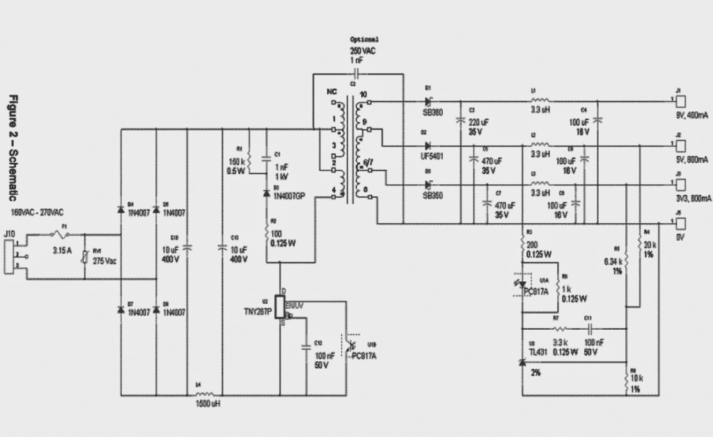
D3, R1, R2, along with C1 build up the primary side clamp-snubber to fix the voltage peak at the Drain pin as soon as its turned-off. D3 is a 1N4007G, a glass-passivated model of the typical 1N4007, with regulated back EMF restoration. Its positioned, in conjunction with R2, to enhance EMI and the intended 3.3V, 5V, 9V outputs.
In a situation where a specific fast recovery diode is difficult to obtain, any other alternative fast diode can be incorporated without an issue.
Output voltage filtering
C3, C5, and C7 become responsible as the bulk output capacitors. C4, C6, and C8, in conjunction with the inductors L1, L2, and L3, constitute second-stage output filters.
Output Feedback Loop
Sensing resistors R4 and R5 detect and identify a probable difference in the amplitude of the 3.3V and 5V
output voltage limits.
Such difference in the voltage, could be as a result of differences in the output connected load or perhaps input voltage, are fed as a reference to the input pin of the TL431 shunt regulator.
The shunt regulator identifies these and compares the same with its in-built voltage reference level to trigger a feedback signal in the form of a current impulse trough U1 B proportional to the to the identified difference detected by R4 and R5.
Opto-coupler U1 immediately shuts down the control loop of the supply voltage by sending the feedback signal current to the output of the ENUV pin on the primary section of the circuit.
The following diagram represents the complete schematic of the 3.3V, 5V, 9V SMPS Circuit
Circuit Diagram
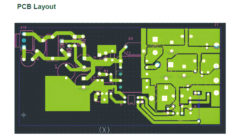
PCB Layout for the proposed multiple voltage output SMPS circuit
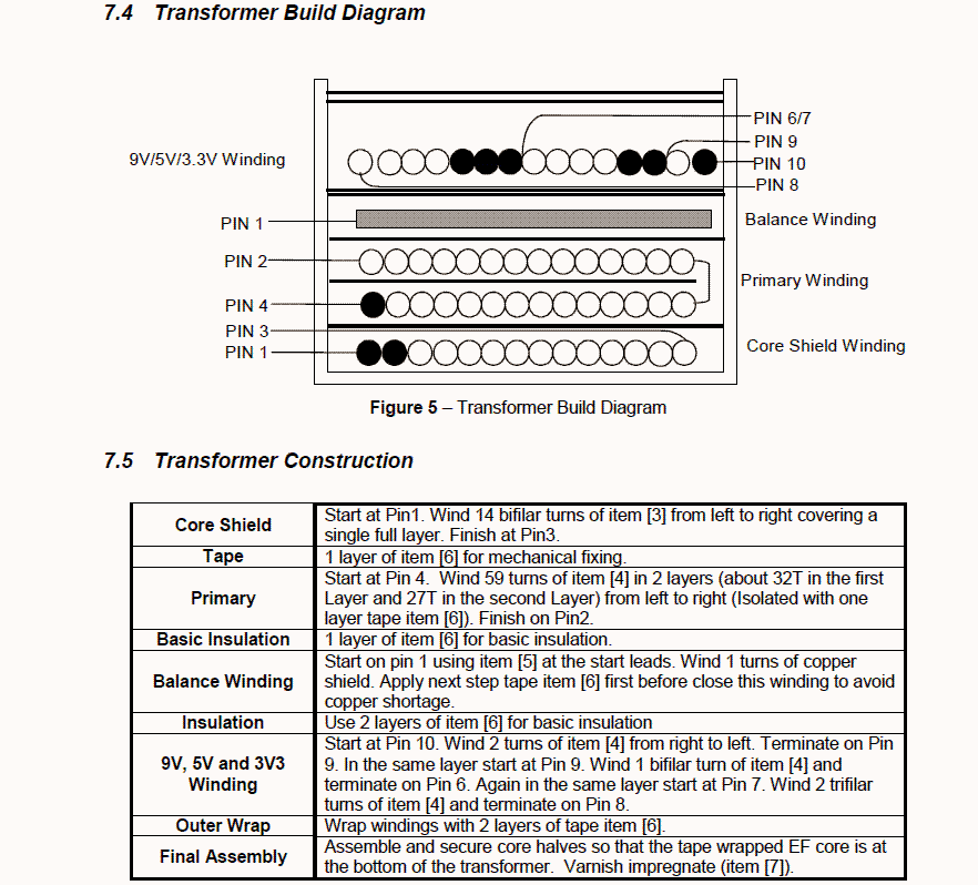
Transformer winding drawing for the above explained multiple voltage output SMPS circuit
Transformer Winding Details
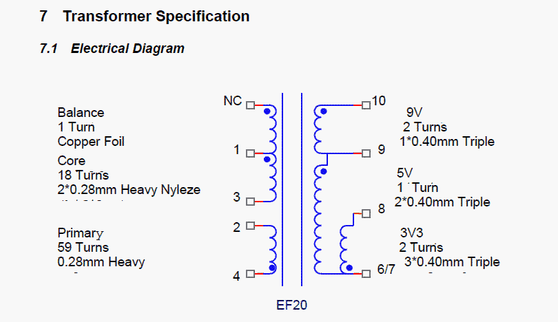
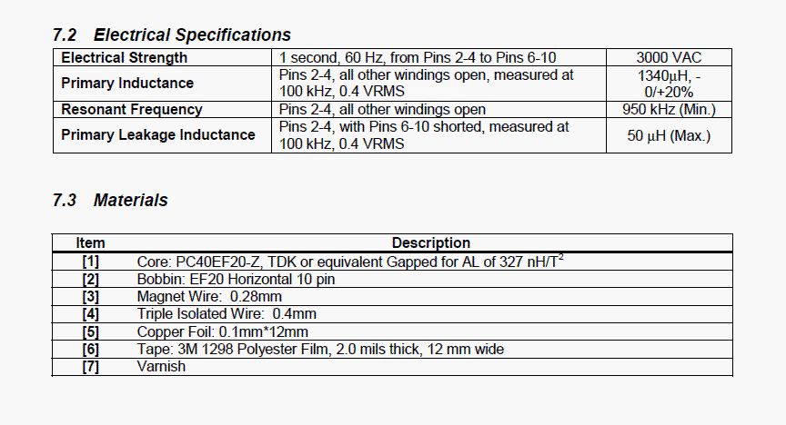
The following gives the transformer specifications for assisting the winding of the turns correctly
Courtesy: https://ac-dc.power.com/system/files_force/PDFFiles/der55.pdf
Questions & Answers
Hello, thank you for your very useful articles. I’m currently training to be an engineer and I have to design a 3V / 200 mA power supply for a smoke detector from the 230V / 50 Hz mains without a transformer, and I can see several ideas. Can you give me some ideas and advice so that I can get on with my project?
Thank you and have a nice day.
Hello, if you are looking for an smps circuit then I would recommend you the following design:
https://www.homemade-circuits.com/220v-smps-cell-phone-charger-circuit/
Thank you very much
I would like to know how the transformer is sized.
Transformer is sized according the wattage, voltage, and current requirements.
Sir please don’t ignore me please
John, I have already replied to you in the previous comments, please refer to the previous replies and proceed accordingly. A 15 amp SMPS circuit is not for newcomers, you are bound to fail 100% if you do it without prior experience and thorough knowledge about SMPS concepts and winding transformers.
Sir now i am challenged my friends just told me that i am a loser i can’t make an power supply i need to prove them wrong.
Give me solution how do I make an 20v and 15amp SMPS i will try to prove them wrong
Help me sir and i will wind up the transformer by my own help me sir help me !
I am not saying that making this can be impossible for me but the transform windings can impossible for me. can I buy a pre winded transformer from the store?
Unfortunately SMPS caanot be built without a transformer and a readymade transformers are not available. However, you can perhaps buy a ready made kit with all the spares from amazon, according to me.
Can you give me a simple digram because i not a engineer so it can be hard for me please sir !
John, An SMPS can never be simple design, and is not recommended for newcomers. If you are new to electronics then you should a buy a readymade unit instead of building it.
Hello sir can you suggest me 24v 10amps SMPS pcb digram ?
Hello John,
You can try the following design with some modifications:
https://www.homemade-circuits.com/smps-2-x-50v-350w-circuit-for-audio/
can u explain(calculation) pi filter section for input and output sections i.e., (C10,L4,C13) & (C3,L1,C4)
There are too valuable too. Thanks.
hello sir,
thank you for your tutorial
I’m designing to board, the output of the first one is 5v, 9V, 12 V – 3A for each one
and the second, 5v, 7v, 12v – 3A
so what I have to change in this circuit to obtain these requirements ?
Thanks in advance
Hello Moataz, sorry, getting 3 amp from the TNY IC may not be possible.
OK
do you have another circuit or can you help me to find another one ?
You can perhaps try modifying the following concept
https://www.homemade-circuits.com/32-v-3-amp-smps-led-driver-circuit/
Dear Sir,
In the circuit diagram above, I found V0 values for 3,3v and 5v outputs as follows;
V01=(1+6,34/10)*2,5=4,085v
V02=(1+20/10)*2,5=7,5V
The results V01 and v02 are not equal to 3.3v and 5v in the circuit diagram.
What is the reason?
Olgun, It can be difficult to judge without a practical test, I think you should build it practically and adjust it to your specific requirements.
So that means the higher the wattage, the battery voltage to be used. Also How can i know the required battery voltage for each kva inverter.
dividing wattage with voltage will give the current rating, select accordingly which may suit your battery specs
Hello sir, can a ferrite transformer inverter of 5kva using 12v dc battery. Pls can you upload the schematic diagram of such circuit. Thanks
that's not possible and is not recommended, just divide 5000 with 12 and you will understand why it is not recommended.
Hi, you can try using two or 3 wires in parallel for the secondary turns in the transformer..this would hopefully increase the current but I am not sure whether the TNY is rated for that or not.
hi
How can i increase the current to 1.5 amps and can you pls give the transformer specifications as given above for just a 5v supply .
hello,
Can i use TNY 266 insted of 267 ?
yes it can be used.