The post presents an SMPS based LED street lamp driver circuit which can be used for driving any LED lamp design right from 10 watts to 50 watts plus.
Using the IC L6565
The proposed 50 watt (and higher) LED street light driver circuit uses the IC L6565 as the main control device, which is basically a current mode primary controller chip especially built for quasi-resonant ZVS fly-back converters. ZVS stands for zero voltage switching.
The chip implements the said quasi-resonant function by sensing the demagnetization of the transformer and by subsequently switching the mosfet for further actions.
The Feed Forward Feature
A feed forward feature enables the IC to compensate for the variations of the mains voltage which in turn takes care of the converters power handling capability.
In case the connected load is lower than the specified magnitude, the device correspondingly adjusts and compensates the operating frequency without affecting the ZVS feature by much.
In addition to the above features the IC also includes a built-in current sensor, an error amplifier with accurate reference voltage and a versatile two step protection against overcurrent load conditions.
More details regarding the IC L6565 can be found in its datasheet.
The remaining configuration of the converter is standard and may be understood as follows:
Circuit Operation
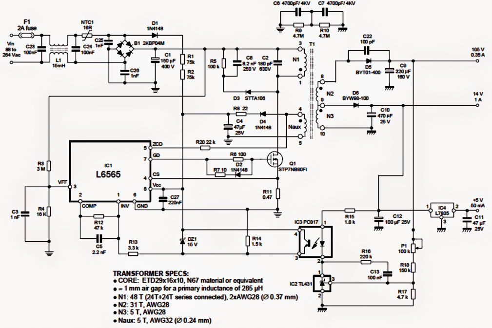
The mains 120/220V AC is fed to the bridge rectifier B1 via an EMI filter L1.
The rectified voltage is filtered by C1 and applied to the primary section of the converter which comprises the IC L6565 along with the ferrite transformer primary winding and the switching mosfet.
The IC instantly triggers itself and the mosfet, implementing the featured ZVS operations and switching the mosfet at the specified compensated rate, depending upon the mains input level.
The output of the transformer responds to this and generates the required voltages across the respective winding.
The outputs are appropriately rectified and filtered by the connected fast recovery diodes and high voltage filter capacitors.
N2 can be seen specified with an output of 105V at 350mA.
Other auxiliary winding which are included produce 14V (@1amp) and 5V (@50mA) which may be used for other relevant applications such as charging a battery or illuminating a pilot lamp.
The opto IC3 is as usual included for ensuring a constant output in terms of voltage, current and for providing the relevant output information to the chip so that the necessary protective actions can be enforced by the chip during adverse situations.
Transformer winding Details
The transformer winding details for the proposed 50 watt street light driver circuit is furnished in the diagram itself.
In the above sections I have explained an SMPS design which can be used for driving a 50 watt LED lamp made from 50 numbers of 1 watt LEds. Here I have explained the connection details of the LEDs with the driver circuit.
LED Configuration
Assuming we want to use 1 watt LEDs (recommended) for the proposed 50 watt street light, we would require 50 numbers of these LEDs to be configured with the circuit.
Referring to the above descriptions, we see that one of the outputs is specified with 105V at 350mA.
This particular output becomes the preferable one for driving 50 numbers of 1 watt LEds, although it could be implemented only after through some serious calculations.
If we connect all the 50 LEDs in parallel would call for an output equal to 50 x 3.3 = 165V, but since this output doesn't seem to be available, we could opt for a more feasible series/parallel connection with the LeDs.
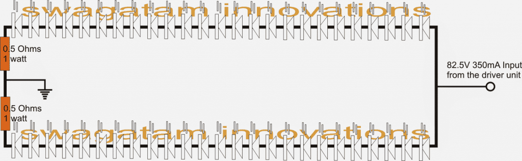
So we can make two strings of LEDs, each consisting of 25 nos of LEDs, and connect these two strings in parallel.
However, involving two strings would mean that the LEDs would now require 3.3 x 25 = 82.5V @ 700mA
The above values once again seem to be not matching the driver output specs.
No issues, the above values can be matched by doing a few simple tweaks with the relevant output winding of the driver transformer.
Current Level Adjustment
The current (amps) can be increased by replacing the N2 winding with a bifilar winding consisting of two 28AWG wires wound simultaneously.
This will take care of the required 700mA current since now we have used two wires in parallel for N2 instead of the recommended single wire.
Next, for reducing the voltage from 105v to 82.5V, we simply need the above winding to be made into 24 turns instead of the indicated 31 turns.
That's it, once the above couple of simple tweaks are done, the driver now becomes perfectly suitable for driving the proposed 50 watt LED lamp module.
The LED connection details can be witnessed in the following schematic diagram:


Questions & Answers
Is this kit sold anywhere for DIY assembly, including the board?
I think similar kits might be available at amazon.
Boa tarde.
Você tem uma possibilidade de deixar esta driver com alto fator de potencia ?
Se sim poderia postar o circuito?
I’ll try to figure it out!!
all well swagatam sir just one more help required is this circuit design for constant current constant voltage kindly please confirm
it's a constant voltage but might not be a constant current power supply
sorry, actually it is a constant current and constant voltage design!
The opto-coupler maintains the constant voltage while R11 maintains the constant current feature
dear sir
we have started buiding the PCB for the above 50 watt circuit looking forward to your help
regards
Anirudh For MARC
Anirudh, If you have started building it it's your wish, I have already warned you that the above circuit is for the experts in "power electronics", it's NOT recommended for a newcomer…I won't be able to help you if you get stuck in the middle.
dear swagatam sir
you can try using 10 more strands in parallel for N2+N3 winding kindly please say what is this
for 10amp supply you will need a 10amp fuse, not a 2amp fuse
dear swagatam sir
in the given circuit there ia a 2A fuse is it okay for 32V 10 amps output kindly please state
Dear Anirudh,
P1 is a preset, If you are new in the field of electronics then you should not attempt the above circuit because it's strictly for the experts.
dear swagatam sir
anirudh here from marc what is P1 also the 120 watt 32 volt dc 10 amp circuit will it give constant current as well as constant voltage kindly please say sir
dear swagatam sir how can we make it work for 120 watt 32 volt dc 10 amp circuit
Marc, you can adjust P1 to set the output to 32V, for increasing current to 10A you can try using 10 more strands in parallel for N2+N3 winding
What do you suggest for 230AC to 16v @300mA , I want to power five 1w LED in series with each @ 3.2 volts. A constant current source ?
…and 25 turns at the secondary of the transformer
you can make the following smps circuit for it:
https://www.homemade-circuits.com/2014/02/220v-smps-cell-phone-charger-circuit.html
use 15V zener for ZD