An electronic incubator thermostat circuit shown in this article is not only simple to build but is also easy to set and acquire exact tripping points at various different set temperature levels. The setting may be completed through two discrete variable resistors.
How Incubators Work
An Incubator is a system where bird/reptile eggs are hatched through artificial methods by creating a temperature controlled environment.
Here the temperature is precisely optimized to match the natural incubating temperature level of eggs, which becomes the most crucial part of the whole system.
The advantage of artificial incubation is faster and healthier production of the chicks compared to the natural process.
Sensing Range
The sensing range is quite good from 0 to 110 degrees Celsius. Switching a particular load at different threshold temperature levels doesn’t necessarily need complex configurations to be involved in an electronic circuit.
Here I have explained a simple construction procedure of an electronic incubator thermostat. This simple electronic incubator thermostat will very faithfully sense and activate the output relay at different set temperature levels from 0 to 110 degree Celsius.
Drawbacks of Electromechanical Thermostats
The conventional electromechanical temperature sensors or thermostats are not very efficient due to the simple reason that they cannot be optimized with accurate trip points.
Normally these types of temperature sensor or thermostats fundamentally use the ubiquitous bimetal strip for the actual tripping operations.
When the temperature to be sensed reaches the threshold point of this metal, it bends and buckles.
Since the electricity to the heating device passes through this metal, it’s buckling causes the contact to break and thus power to the heating element is interrupted - the heater is switched off and the temperature starts falling.
As the temperature cools, the bimetal starts straightening to its original form. The moment it reaches its previous shape, the electricity supply to the heater is restored through its contacts and the cycle repeats.
However, the transition points between the switching are too long and not consistent and therefore not reliable for accurate operations.
The simple incubator circuit presented here is absolutely free from these drawbacks and will produce comparatively high degree of accuracy as far the upper and the lower tripping operations are concerned.
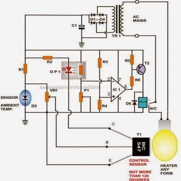
Parts List
- R1 = 2k7,
- R2, R5, R6 = 1K
- R3, R4 = 10K,
- D1---D4 = 1N4007,
- D5, D6 = 1N4148,
- P1 = 100K,
- VR1 = 200 Ohms, 1Watt,
- C1 = 1000uF/25V,
- T1 = BC547,
- T2 = BC557,IC = 741,
- OPTO = LED/LDR Combo.
- Relay = 12 V, 400 Ohm, SPDT.
Circuit Operation
We know that every semiconductor electronic component changes its electrical conductivity in response to the varying ambient temperature.
This property is exploited here to make the circuit work as a temperature sensor and controller.
Diode D5 and transistor T1 together form a differential temperature sensor and interact greatly with each other with changes in the respective surrounding temperature.
Also since D5 acts as the reference source by staying at the ambient temperature level should be kept as far as possible from T1 and in open air.
Pot VR1 may be used externally to optimize the reference level set naturally by D5.
Now assuming D5 is at a relatively fixed temperature level (ambient), if the temperature in question around T1 starts rising, after a particular threshold level as set by VR1, T1 will begin to saturate and gradually start conducting.
Once it reaches the forward voltage drop of the LED inside the opto-coupler, it will start glowing correspondingly brighter as the above temperature rises.
Interestingly as the LED light reaches a particular level, further set by P1, IC1 picks this up and instantly switches its output.
T2 along with relay also respond to the IC’s command and respectively actuate to trip off the load or the heat source in question.
How to Make an LED/LDR Opto-Coupler?
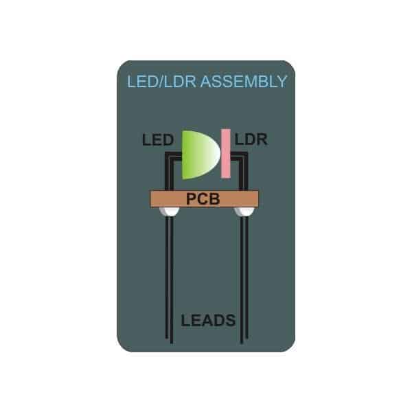
Making a homemade LED/LDR opto is actually very simple. Cut a piece of general purpose board about 1 by 1 inch.
Bend the LDR leads near its “head.” Also take a green RED LED, bend it just as the LDR (See figure and Click to Enlarge).
Insert them over the PCB so that the LED lens point is touching the LDR sensing surface and are face to face.
Solder their leads at the track side of the PCB; do not cut off the remaining excess lead portion.
Cover the top with an opaque lid and make sure its light proof. Preferably seal off the edges with some opaque sealing glue.
Let it dry. Your home made LED/LDR based opto-coupler is ready and may be fixed over the main circuit board with its leads orientations done as per the electronic incubator thermostat circuit schematic.
Update:
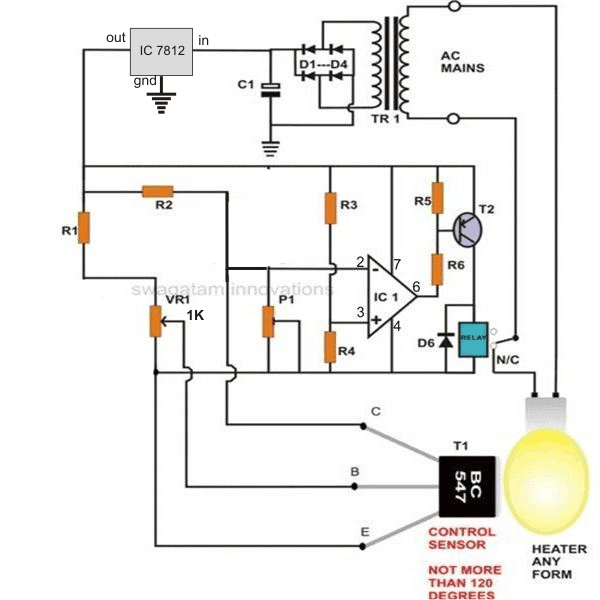
After some careful investigation it became evident that the above opto-coupler can be totally avoided from the proposed incubator controller circuit.
Here are the modifications which needs to be made after eliminating the opto.
R2 now directly connects with the collector of T1.
The junction of pin#2 of IC1 and P1 hooks up with the above R2/T1 junction.
That's it, the simpler version is now all ready, much improved and easier to handle.
Please check-out the much simplified version of the above circuit:
Adding a Hysteresis to the above Incubator Circuit
The following paragraphs describes a simple yet accurate adjustable incubator temperature controller circuit which has a special hysteresis control feature.
The idea was requested by Dodz, let's know more.
Technical Specifications
Actually, I have a little request to make and I hope this does not burden you that much. I have been researching on analog thermostat for my homemade incubator.
I learned that there are probably dozen of ways of doing it using different sensors such as thermistors, bi-metallic strip, transistors, diodes, and so on.
I want to build one using either of these methods but I find the diode method as the best one for me because of the availability of the components.
However I could not find diagrams that I am comfortable experimenting with.
The present circuit is good but could not follow much regarding setting the high and low temp levels and adjusting the hysteresis.
My point is I want to make thermostat with sensor that is diode-based with adjustable hysteresis for a homemade incubator.
This project is for personal use and for our local farmers that venture into duck and poultry hatching.
I am an agriculturist by profession by I studied (vocational very basic course) electronics as a hobby. I can read diagrams and some components but not very much.
I hope you can make me this circuit. Lastly, I hope you can make simpler explanations especially on setting the temperature thresholds and the hysteresis.
Thank you very much and more more power to you.
The Design
In one of my previous posts I have already discussed an interesting yet very simple incubator thermostat circuit which uses an inexpensive transistor BC 547 for detecting and maintaining the incubation temperature.
The circuit includes another sensor in the form of a 1N4148 diode, however this device is used for generating the reference level for the BC547 sensor.
The 1N4148 diode senses the ambient atmospheric temperature and accordingly "informs" the BC547 sensor to adjust the thresholds appropriately.
Thus during winter, the threshold would be shifted on the higher side such that incubator stays warmer than during summer seasons.
Everything seems to be perfect in the circuit except one issue, that is the hysteresis factor which is completely missing there.
Without an effective hysteresis the circuit would respond fast making the heater lamp switch at rapid frequencies at the threshold levels.
Moreover adding a hysteresis control feature would allow the user to manually set the average temperature of the compartment as per individual preferences.
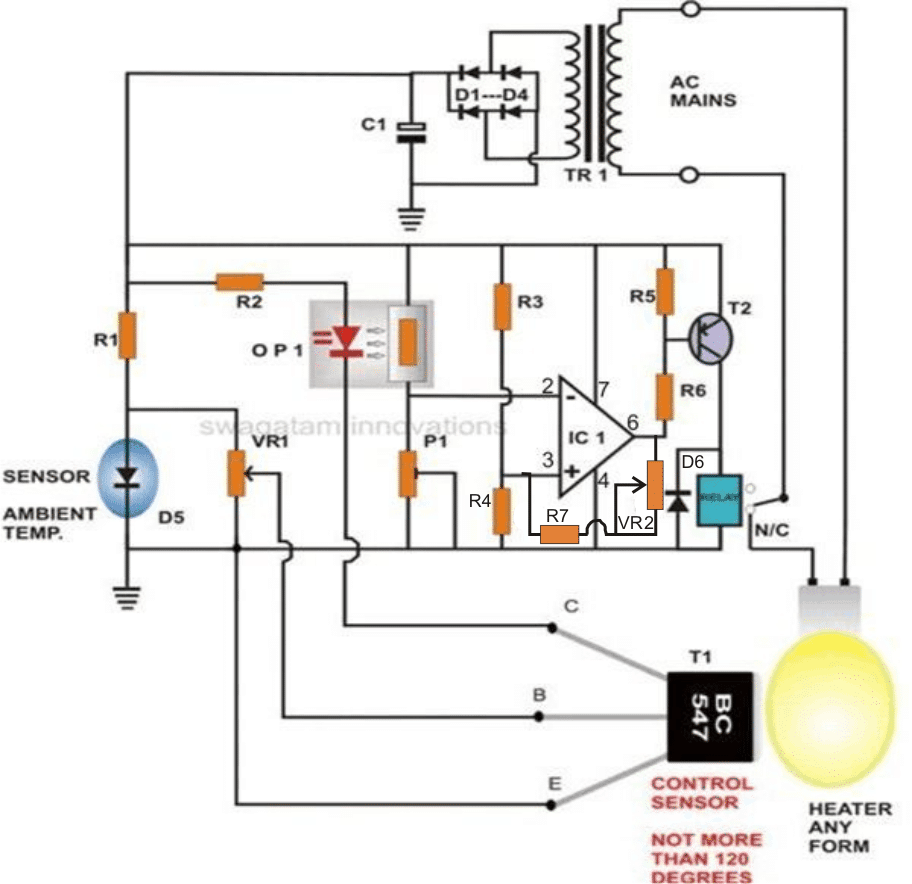
The following diagram shows the modified design of the previous circuit, here as we can see, a resistor and a pot has been introduced across pin#2 and pin#6 of the IC.
The pot VR2 can be used for adjusting the OFF time of the relay as per the desired preferences.
The addition almost makes the circuit a perfect incubator design.
Parts List
- R1 = 2k7,
- R2, R5, R6 = 1K
- R3, R4, R7 = 10K,
- D1---D4 = 1N4007,
- D5, D6 = 1N4148,
- P1 = 100K,VR1 = 200 Ohms, 1Watt,
- VR2 = 100k pot
- C1 = 1000uF/25V,
- T1 = BC547,
- T2 = BC557,IC = 741,
- OPTO = LED/LDR Combo.
- Relay = 12 V, 400 Ohm, SPDT.
Incubator Thermostat using IC LM35 Temperature Sensor
A very simple egg incubator temperature controller thermostat circuit using LM 35 IC is I have explained in this article. I have explained more.
Importance of Temperature Controlled Environment
Anybody involved in this profession will understand the importance of a temperature controller circuit which should be not only reasonably priced but also have features like precise temperature control and manually adjustable ranges, otherwise the incubation could get hugely affected, destroying most the eggs or developing premature offspring.
I have already discussed an easy to build incubator thermostat circuit in one of my earlier posts, here we'll learn a couple of incubator systems having easier and much more user friendly setting up procedures.
The first design shown below uses an opamp and a LM35 IC based thermostat circuit and indeed this looks quite interesting due to its very simple configuration:
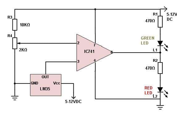
The idea presented above looks self explanatory, wherein the IC 741 is configured as a comparator
with its inverting pin#2 input pin is rigged with an adjustable reference potentiometer while the other non-inverting pin#3 is attached with output of temperature sensor IC LM35
The reference pot is used to set the temperature threshold at which the opamp output is supposed to go high.
It implies that as soon as the temperature around the LM35 goes higher than the desired threshold level, its output voltage becomes high enough to cause pin#3 of the opamp to go over the voltage at pin#2 as set by the pot.
This in turn causes the output of the opamp to go high. The outcome is indicated by the lower RED LED which now illuminates while the green LED shuts off.
Now this outcome can be easily integrated with a transistor relay driver stage for switching the heat source ON/OFF in response to the above triggers for regulating the incubator temperature.
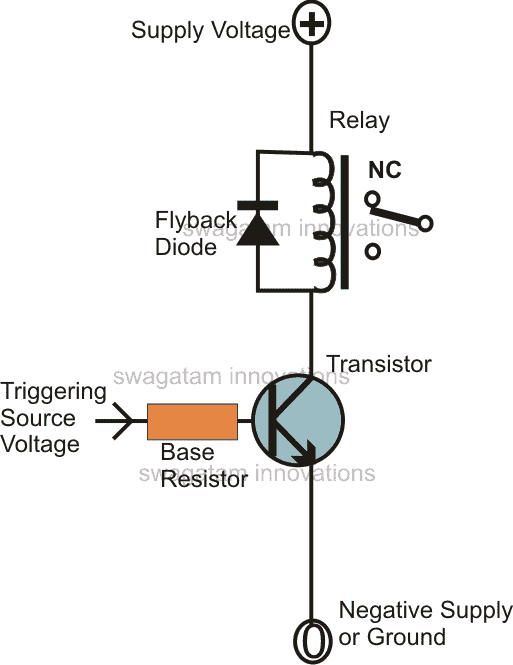
A standard relay driver can be seen below, wherein the base of the transistor may be connected with pin#6 of the opamp 741 for the required incubator temperature control.
The Relay Driver Stage for Switching the Heater Element
Incubator Temperature Controller Thermostat with LED Indicator
In the next design we see another cool incubator temperature controller thermostat circuit using an LED driver IC LM3915
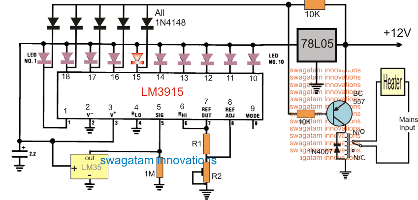
In this design the IC LM3915 is configured as a temperature indicator through 10 sequential LEDs and also the same pinouts are used for initiating the ON/OFF switching of the incubator heater device for the intended incubator temperature control.
Here R2 is installed in the form of a pot and it constitutes the threshold level adjustment control knob and is used for setting up the temperature switching operations as per the desired specifications.
The temperature sensor IC LM35 can seen attached to the input pin#5 of the IC LM3915. With rise in temperature around the IC LM35 the LEDs begin sequencing from pin#1 towards pin#10.
Let's assume, at room temperature the LED#1 illuminates and at the higher cut-off temperature the LED#15 illuminates as the sequence progresses.
It implies that pin#15 may be considered the threshold pinout after which the temperature could be unsafe for the incubation.
The relay cut-off integration is implemented according to the above consideration and we can see that the base of the transistor is able to get its biasing feed only upto pin#15.
Therefore as long as the IC sequence is within pin#15, the relay remains triggered and the heater device is held switched ON.
However, as soon as the sequence crosses over pin#15 and lands on pin#14, pin#13 etc. the transistor biasing feed is cut off and the relay is reverted towards the N/C position, subsequently switching OFF the heater..... until temperature normalizes and the sequence restores back below the pin#15 pinout.
The above sequential up/down drift keeps on repeating in accordance with the surrounding temperature and the heater element is switched ON/OFF maintaining almost a constant incubator temperature as per the given specifications.
Solar Powered Egg Incubator Circuit
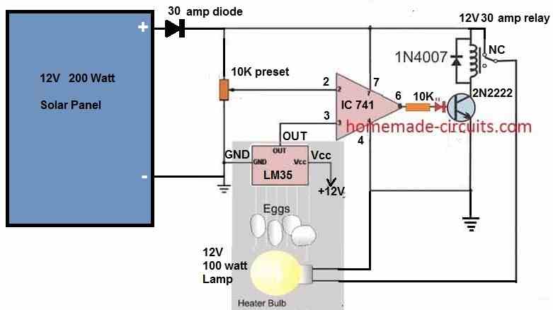
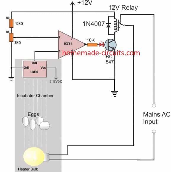
The solar-powered incubator circuit described uses an op-amp configured as a comparator to control the operation of a heater bulb for eggs. The working of the circuit can be understood from the following points.
Solar Panel: The circuit is powered by a 12V 200W solar panel, which provides the required operating power to the circuit and the lamp.
LM35 IC Heat Sensor: An LM35 temperature sensor IC is connected to the non-inverting input of the op-amp (741) to detect the heat generated by the heater bulb. The LM35 provides an output voltage proportional to the temperature it senses.
10K Preset: A 10K preset resistor is connected to the inverting input of the op-amp. This resistor sets the reference voltage for comparison with the LM35 output.
By adjusting the preset resistor, the desired temperature threshold can be set.
Op-Amp (741) Comparator: The op-amp (741) is configured as a comparator. The IC the voltages at its inverting and non-inverting inputs.
As soon as the voltage at the non-inverting input goes above the voltage at the inverting input, the output of the op-amp becomes high.
Transistor Relay Driver: A transistor relay driver circuit is connected to pin 6 (output) of the op-amp.
The relay driver provides the necessary current to activate a relay when the op-amp output goes high.
Relay: The relay acts as a switch that controls the power supply to the heater bulb. When the op-amp output goes high, the relay is activated, turning off the bulb.
Conversely, when the op-amp output goes low, the relay is deactivated, turning on the bulb.
Circuit Description
The functioning of the circuit is as follows:
Initially, the heater bulb is turned on, and the LM35 measures the temperature.
The op-amp compares the LM35 output voltage with the reference voltage set by the 10K preset resistor.
If the measured temperature exceeds the set threshold, the op-amp output goes high, activating the relay and turning off the heater bulb.
As the temperature decreases below the threshold, the op-amp output goes low, deactivating the relay and turning on the heater bulb again.
This cycle repeats continuously, maintaining the temperature within the desired range.


Questions & Answers
Thanks!
VR1 may be used for setting-up the cut off threshold, which must not exceed 110 degree Celsius (max), while P1 may be used for fine tuning the set cut off point.
The BC547 is used as the heat sensor here and therefore must be kept near the heat source.
The blue part is the relay coil……please click the diagram to enlarge and check the details.
That's great, if you look carefully you will find that actually the 1N4148 is not required, so you can simply remove it, and make VR1 into a 1K preset. Finished, now adjust the 1K preset for the desired actions.
However in this case your power supply must be regulated, so add a 7812 IC after the bridge for making the supply stabilized.
connect one LED from pin6 to positive, another from pin6 to ground, both LEDs should have individual series 10k resistors.
one of them will indicate ON, the other one as OFF.
altenative of 741 IC
hi sir in my place there is no an IC 741 and 4060 what are their altenertive
altanative of bc557 transistor
if you don't get these, you won't get the other alternatives also for sure, consult the dealer, he will know better.
for second diagram P1 = 1k,
BC547 is the only sensor near heat source.
keep P2 at center, set VR1 roughly to activate the relay at about 70 degree temp, after this only P2 may be used for getting other desired thresholds.
….correction: for second diagram VR1 = 1k, P1 = 100k
pin4 line of 741 is the ground
Connect an LED in between R2 and collector of BC547…..keep pin2 of 741 disconnected with R2.
Switch ON power and heat BC547 slightly at about 60 degree and adjust VR1 such that the LED starts glowing dimly…that's all your circuit is set.
Now connect pin2 of 741 back in position, repeat the procedure and adjust P1 to activate relay at any desired temperature within 110 degree.
you can use soldering iron to heat the transistor…but be careful not to overheat BC547
It basically depends on Ub (supply voltage), R1 and R2.
R1 and R2 may be selected with the following formulas:
R1 = (Ub – 0.6)/5 (kohms)
R2 = (Ub – 1.5)/15 (kohns)
these are the only computations available.
to the pin4 rail of IC741
Please are the D5 and D6 diodes some heat censors?
D5 and T1 are the sensors….T1 is the main sensor which needs to be kept near the heat source to be measured.
Hey sir..
I was the one who said 8/10 egg's
hatched, please read that
comment again before answering
this.
i did 4 boards with the modified
circuit with the following
modifications
1. gave LED in series with 10k.
2.hyst 100k preset in series with
10k resister.
3. A capacitor across base and
positive.
Done everything as yu said.
Still problem is'nt solved, all
boards giving same problem.
It works good and fine first day
(completely accurate), but after a
day the temp on/off range
changes again.
Sometimes it never turns OFF or
ON, couldn't findout what is the
prob.
i think the room temperature
again affecting its behaviour.
Hi Rithesh,
Remove the 100k hyst preset link, we do not need it at all because the heat will never rise or fall quickly, so a hysteresis feature is not required.
Did you try the last circuit as given in the above article??
Make it exactly as it's given…don't forget to use a 7812 IC with the circuit.
Use good quality preset for both VR1 and P1.
Make the above mods, it will work.
With 1N4148 removed room temperature will not affect the circuit in anyway.
In future you could think of replacing VR1, P1 with fixed resistors.
HIE SIR THANKS BUT MY QUESTION IS TO WHAT CAPACITY DOES THIS CIRCUIT HOLD IN TERMS OF NUMBER OF EGGS IN THE INCUBATOR AND HOW LONG DOES IT TAKE TO HATCH
Hi Ngoni,
It will depend on how many heat sources you are using, for each heat source you will have to incorporate an individual circuit.
Hatching period is not known to me.
ok bro so for one individual circuit what is the capacity then how many eggs per circuit are we looking at
It will depend on the area used, and the wattage of the heat source, it can be dimensioned to any desired range as per requirements.
thanks bro you are helping so much .is it proper to use one heat source for a 5m by 1.5m area and the heat source is an infrared light
I have neve rused an IR light for heating purpose, how much heat does it produce?
l want to use any area of 5m by 1.5m so is one infrared light ok as a heat source
hie bro the infrared light a 250watt rating and what is the most desired heat source
It will depend on the egg hatching specifications, you can get the information online regarding the right temperature required for hatching eggs. Then you can adjust the above circuit for maintaining the particular temperature range, throughout.
how many eggs would the box contain to do the process 😀
will depend on the size of the heat source.
hello sir swagatam, i already made the simplified version of your design, but it wont turn off the heat source ,,, if i adjust the vr1 manually, it will initialize turn on/off the relay but it wont turn off/on automatically to my desired temp, will you email me the step by step procedure in setting up my desired temp, cut-off,, tanx in advance
hello Oliver, i am sorry it's not that easy.
you can include an LED immediately after R2 and in series with it.
Allow the transistor BC547 to heat up to around 70 degrees, and adjust VR1 to just make the LED glow.
At this point you can try adjusting P1 for the required switching of the relay, or if it's already switched ON adjust P1 to just switch it OFF and then readjust to just switch it ON back.
The circuit is set now and will repeat the actions every time the temp reaches the set threshold
I hope you got it.
tanx a lot sir for the quick reply,,, maybe i can try the adjustment by next week coz i am out of town right now….i will follow the adjustment you say and update here the result ,,,
OK!
sir, i have a temperature controller built-in-type, in its user guide denote that use a snubber circuit for long life of relay of temperature controller, how can select the values of resistor and capacitor which involved in snubber circuit? i'm waiting for your suggestion….
Khalid, that'll depend on many factors, you'll need to calculate it through an online snubber calculator software.
Good day Sir Swagatam, i will be making this projet and i will base on your circuit as a reference =) I only have samome basic concepts questions.
What will happen to the Light (heater) if the heat goes up in the sensor? Will it dim or will it turn off?
Which pots are assigned to set the temperatures from 0-120? Can it be made in a way that it that if (assuming) i set the min temperature to 20 degrees it will light up and shine brighter if lower temperatures are achieved? And 35 degrees it will dim?
Or i got it all wrong? Hehehe sorry for asking a lot of question. I'm kinda new to these.
Good day Lloyd, the heater will shut off for a moment if the heat exceeds above the set high threshold, and will switch ON back as the temperature falls below the lower threshold.
The setting up adjustments could be done in the following manner:
connect a RED LED in series with R2, and adjust VR1 until this LED begins glowing at the required high temperature from the heater (not to exceed 100 degrees C), ignore the relay response during this setting.
the heater should not be connected through the relay rather directly through a manual switch
Now once the above position is reached, carefully adjust P1 so that the relay just deactivates, if it's already in a deactivated position, force it to activate by adjusting P1 and immediately adjust it back to deactivate it, all these must be while the red LED is still glowing bright.
your setting up procedure is complete now, connect the heater via the relay contacts as shown in the diagram, check and enjoy the automatic response as per the above settings.
…for a dimming and brightening type of response you may refer to the following design:
https://www.homemade-circuits.com/2013/01/automatic-temperatureclimate-controlled.html
Hi Sir, I don't know if my comment have been published. But just to be sure, i want to thank you again and i appreciate it very much for replying to my questions!
I cannot find any way to private message you so i will put my request here to you..
I changed my mind, instead i wanna make a 12v dc temperature controlled fan.
I want it to make as such, it will turn on at 20 degrees and it will turn off below 20 degrees. If it reaches 20 degrees above, the speed of the fan will go faster aswell. The heat source will be the surrounding. And can we possibly add a LED, that will glow brighter aswell? I need as an example of a closed loop feedback control system. Please..
Thank you again sir! I'll wait for your reply. Regards! (my gmail is here : rreddmallari@gmail.com)
Hi Lloyd, you can try the following circuit:
1.bp.blogspot.com/-YmlmSYSqUTU/U7UWfVEzlHI/AAAAAAAAHcc/E6Uh_aI7rpA/s1600/solar+ater+heater+regulator+for+drip+irrigation.png
Replace the heater with the fan, and the 9v supply with 12V
Connect a red LED in series with the base of the transistor for the indications.
Adjust P1 precisely so that the fan triggers at 20 degrees approximately.
in fig 2 R1 isnt grounded ……. am i ri8???
no, it's correctly shown in the diagram, R1 and the pot form a potential divider for the transistor base
….yes it should not be grounded
can u give me info..about 12v dc motor
12v DC works on 12V DC power
Sir … I really need help on how to construct a DC thermostat with LCD display ….. With can trigger on a fan at 50centigrade only … .. Any link or help will be appreciated
Ekenekk@gmail.com
Sir I need help on how to construct a DC thermostat with LCD display , which can equally trigger on a fan at 50degree centigrade ….. Pls this is my project … I need urgent help … Any link or help will be highly appreciated …
Ekenekk@gmail.com
Hi Ekene, I'll try to publish it soon, do keep in touch.