The electronic thermostat explained here can be used to control the room temperature by appropriately switching (turning on and off) a heating device.
By: R.K. Singh
Operational details of electronic thermostat
The circuit employs a thermistor NTC (negative temperature coefficient) as the sensor device.
- As long as the ambient temperature stays higher than the value prefixed by the potentiometer, the relay correspondingly remains inactivate and the red LED may be seen lit.
- In an event of the ambient temperature getting lower than the set value, the relay is activated and the green LED is illuminated.
The potentiometer needs to be carefully adjusted in order to get the desired effects.
To adjust the proposed transistor thermostat circuit, the NTC is enclosed inside a glass tube and its leads are terminated out through long wires so that it can be placed over the desired location for the required sensing.
The circuit is set by placing the thermistor glass tube along with a mercury thermometer inside a container filled with melting ice water, and in the next procedure its placed at ambient temperature and finally close to a gas burner for implementing all the setting levels.
In each of the above mentioned cases, the point at which the green LED just lights up is located by gently manipulating the pot knob toward the maximum and marking it with a line over the knob dial in order to make the relevant temperature calibrations, these markings are then appropriately labelled with the respective temperatures which are recorded simultaneously on the associated thermometer.
The circuit operation is quite straightforward and can be understood by assessing each transistor cut off and triggering states.
For so long as the NTC resistance is very high (when the ambient temperature is low) causes the transistor T1 to go into saturation provided the potentiometer setting permits this.
Considering the above situation is enabled the transistors T1 T2 T3 and T4 saturate and also activate the relay.
The relay employed may be a double contact and each time it is activated two operations are executed, one pair of contacts to switch the LEDs and the other to activate the heater or the desired load.
The capacitor C1 makes sure sudden changes in the value of the NTC.
Circuit Diagram
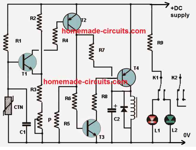
Bill Of Material for the above transistor thermostat circuit:
- Resistors:
- R1, R4, R6: 10K,
- R2: 12K,
- R3: 6.8K,
- R5: 33K,
- R7: 470K,
- R8: 2.2K,
- R9: 560 ohms.
- P = Potentiometer Linear 10K.
- NTC: Negative temperature coefficient 10K.
- Capacitors:
- C1: 100nF,
- C2: 47uF, 10V (electrolytic capacitor).
- LEDs: 1 red, 1 green
- Transistors
- T1 and T3: 2N2222,
- T2: 2N2907,
- T4: 2N2905
- Relay: 12V DPDT.


Questions & Answers
Good circuit Sir,how can I use the same circuit to shut down a diesel engine when it reaches about 80 degrees Celsius.I know I can use the relay contacts to switch the fuel solenoid on and off but the problem is modifying the circuit using an engine tempreture sensor in place of the thermistor to energize the relay at 80 degrees Celsius.Please help🙏🏼
Thank you Geofrey,
Is your existing sensor referenced to ground, if yes then you can simply replace the CTN shown in the above diagram with your existing temperature sensor. Let me know if you have any further doubts…
Hello, good afternoon, Mr. Swagatam. I would like to ask if you have a simple thermostat circuit with NTC to activate a relay, but once the relay is activated, it must remain active for about 1 minute even if the temperature drops.
Thank you very much
Good morning Carlos, I think the first circuit from the following article can be customized as per your needs:
https://www.homemade-circuits.com/make-simple-refrigerator-thermostat/
The R5 value decides how long the load stays active after the heat is removed.
Dear Swagatam,
This circuit is exactly what I was looking for. My planned use case is to control a 12 VDC 30 W silicone heat pad to warm car battery. Up here in Finland it is wise to warm up a lead acid battery because in temperatures far below 0 degrees Celsius the battery will not take in charge current nearly as much as in 20 degrees Celsius.
Thus a question on the operating voltage: will the circuit handle voltages between 10 volts (cold cranking voltage drop) to 14,8 volts (maximum charging voltage of AC powered battery chargers used to keep the battery topped up)?
To me it seems like the circuit should handle this variation without problems. I wanted to ask this because there might be others who also would like to use the circuit in automotive or maritime applications. Mentioning nominal operating voltage and usable voltage range would enhance the possible uses of this very fine circuit of yours.
All the best,
Elias
Thank you Elias, for posting this interesting question.
Yes definitely this circuit can be used with DC voltages upto 14V or above.
However, I was wondering from where the power will come to heat up the heating pad?
There’s another similar circuit which you can consider and it is much simpler:
https://www.homemade-circuits.com/temperature-controlled-relay-switch-circuit/
This other circuit you linked is very suitable as well and much simpler. Thank you! Initial idea would be to get the operating power to the thermostat circuit from battery terminals and the power to heat the pad from external AC powered battery charger. However – is the relay enough for galvanic isolation? The operating DC and the heat pad power DC would come from the same galvanically interconnected circuit. This would be the case also if I would like to use the heater while driving, getting the electrcity for the heating pad from the alternator. I already am thinking of a simple circuit that would also switch on the heater only when voltage exceeds a certain, preferably adjustable, voltage like 13,8 volts. In this case the control circuit would switch the heating pad on only if 1) there is an external battery charger connected and operating or 2) the engine is running and alternator working.
Yes, the relay can provide a perfect galvanic isolation between the heat pad power source and the circuit power source which is battery.
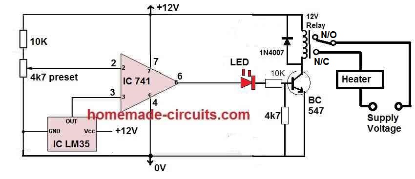
However a thermistor is a crude type of heat sensor and adjusting it accurately can be slightly time consuming, an LM35 based circuit is much accurate and flexible.
The switching of the heat pad at 13.8V is also possible using a simple transistor zener diode setup.
Just perfect! I have difficulties in expressing the joy of finding your site and having these inspiring discussions. As a data privacy activist I also raise my hat high to salute you because you run your own website and have not chosen to use commercial social media platforms like people nowadays mostly do. I will be hanging around following your site and will report with pictures when I have something made ready. Before I start this project I have to assemble a couple of these, however: instructables.com/DIMP-2-Desulfator-in-My-Pocket-2/
Thank you so much, and glad you found this website helpful.
Please feel free to reach out to me if you have any circuit related questions or doubts, I will try to solve them ASAP.
All the best to you.
Hello swagatam how can I convert to circuit for my electric kettle I want to use it as a thermometer for my electric kettle
Hello Okongwu,
If you are intending to measure high temperature of your electric kettle then you should try using a thermocouple circuit.
https://www.homemade-circuits.com/100-c-to-1000-c-thermocouple-temperature-meter-circuit/
Bonjour cher ami et mes très sincères remerciement.
Voudriez vous m’indiquer à quel endroit précis peut on placer un second potentiomètre dans ce circuit? Cela permettra d’avoir un seuil de temperature haut et un seuil de temperature haut réglable à volonté.
Joseph
Hello Joseph, you can add another potentiometer in series with R1, but it will also serve the same function as the existing potentiometer.
Sir, I want to make thermistor circuit with opamp, to activate the relay to run a exhaust fan accurately at a particular temperature.
For eg: turning the relay on at 35°c
Please help me, how can I achieve this task with the help of proper calculation, and also to avoid the unwanted switching of relay at minimum voltage variation.
Yogesh, you can try the first circuit or the last circuit from this article:
https://www.homemade-circuits.com/make-simple-refrigerator-thermostat/
Thank you sir, (•‿•)
I will surely try out any one circuit ,from these two circuits sir
You are welcome Yogesh!
I do not see a power supply.
I design elsctronics from broken old junk.
I would be ecstatic to have you email me. You are brilliant, Swagatam… I have reviewed much of your stuff online.
thank you Jesse, yes the diagram did not have the supply lines clearly marked, but I have corrected the issue in the new updated diagram.
I’m so glad I found Your site! Today, few are involved in the design of analog circuits. In Hungary,(in the past) many young people used to be interested in electronics, because it was not possible to buy many different electronic devices when they were ready. I started in 1969 with a 4-year electronics technical school, then Kando University (then it was only a 3-year college BSC) I am already retired, but thanks to my well-equipped laboratory (Tektronix, HP, R & S, etc.) instruments, still active today I’m. Both of my sons are electrical engineers. I’ve been a sound engineer for several years (my favorite) I like Your site, I’ve already found some interesting topics! I wish You much more success and good health! Marius Bogdan
Thank you for visiting this and liking it! Your valuable feedback is much appreciated! Please keep up the good work!
Yayınladığınız projeleri beğeniyorum. Profesyonel değilim. Elektronik termostatın devresinde T4’ün collektör ayağında bulunan diyotun numarası belli değil belirtirseniz sevinirim. Teşekkür ederim.
The relay diode is 1N4007
Merhaba, Çok Teşekkür ederim. Bu tür projeleriniz bizim için çok değerlidir. Sizlerin bu değerli bilgileri paylaşmanız bizlerin Elektronik dalda çalışmalarımıza çok büyük değer katmaktadır. Saygılarımla,
Thank you very much for your kind feedback!
Alternative two relay switching with one push on switch 12 volt operative circuit
https://www.homemade-circuits.com/single-push-10-step-selector-switch/
replace pin#10 with pin#4
use only pin#2 as the output
yes you can try that