The article below presents a comprehensive know how regarding how buck converters work.
As the name suggests, a buck converter is designed to oppose or restrict an input current causing an output that may be much lower than the supplied input.
In other words it can be considered a step down converter which could be used for acquiring calculated voltages or currents lower than the input voltage.
I have explained more regarding the working of buck converters in electronic circuits through the following discussion:
For a practical buck converter design you may want to read this article
The Buck Converter
Typically you may find a buck converter being used in SMPS and MPPT circuits which specifically require the output voltage to be reduced significantly than the input source power, without affecting or altering the power output, that is the V x I value.
The supply source to a buck converter could be from an AC outlet or from a DC power supply.
A buck converter is used only for those application where an electrical isolation may not be critically required across the input power source and the load, however for applications where the input may be at mains levels then a flyback topology is normally used through an isolating transformer.
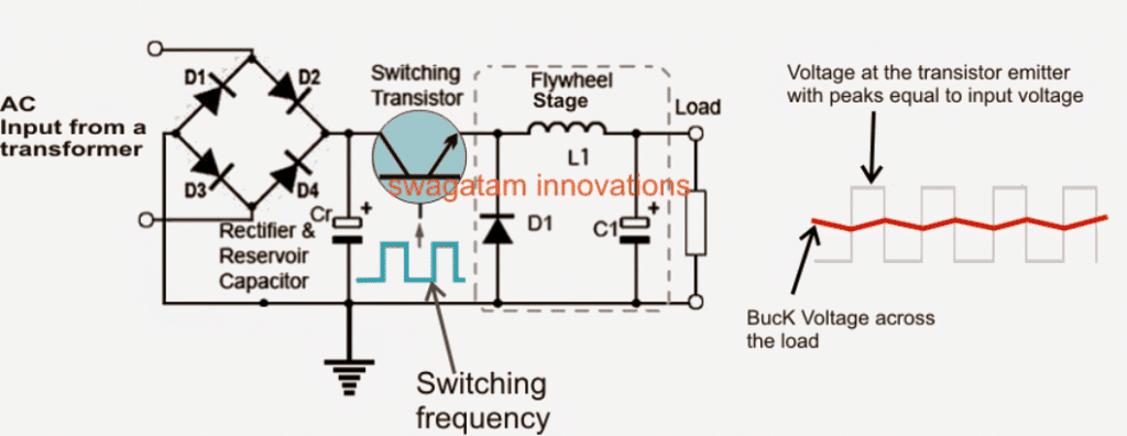
The main device which is used as the switching agent in a buck converter could be in the form of a mosfet or a power BJT (such as a 2N3055), which is configured to switch or oscillate at a rapid rate through an integrated oscillator stage with its base or gate.
The second important element in a buck converter is the inductor L, which stores the electricity from the transistor during its ON periods and releases it during its OFF periods maintaining a continuous supply to the load at the specified level.
This stage is also referred to as the "Flywheel" stage since its function resembles a mechanical flywheel which is able to sustain a continuous and steady rotation with the help of regular pushes from an external source.
Input AC or DC?
A buck converter is basically a DC to DC converter circuit that is designed to acquire a supply from a DC source, which may be a battery or a solar panel.
This could also be from an AC to DC adapter output achieved through a bridge rectifier and a filter capacitor.
No matter what may be the source of the input DC to the buck converter, it is invariably converted into a high frequency using a chopper oscillator circuit along with a PWM stage.
This frequency is then fed to the switching device for the required buck converter actions.
Buck Converter Operation
As discussed in the above section regarding how a buck converter works, and as may be seen the following diagram, the buck converter circuit includes a switching transistor and an associated Flywheel circuit which includes the diode D1, the inductor L1 and the capacitor C1.
During the periods when the transistor is ON, the power passes first through the transistor and then through the inductor L1 and finally to the load. In the process, the inductor due to its inherent property tries to oppose the sudden introduction of current by storing the energy in it.
This opposition by L1 inhibits the current from the applied input to reach the load and reaching the peak value for the initial switching instants.
However in the meantime the transistor enters its switch OFF phase, cutting off the input supply to the inductor.
With the supply switched OFF L1 again faces a sudden change in the current, and to compensate the change it flushes out the stored energy across the connected load
Transistor Switch ‘on’ Period
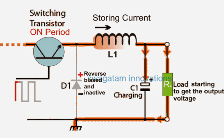
Referring to the above figure, while the transistor is in the switch on phase, it allows the current to reach the load, but during the initial instants of the switch ON the current is heavily restricted due to the inductors opposition to the sudden application of the current through it.
However in the process the inductor responds and compensates the behavior by storing the current in it, and in the course some portion the supply is allowed to reach the load and also to the capacitor C1, which also stores the allowed portion of the supply in it.
It should also be taken into account that while the above happens, D1 cathode experiences a full positive potential which keeps it reverse biased, making it impossible for the L1's stored energy to get a return path across the load via the load. This situation allows the inductor to keep on storing the energy into it without any leakages.
Transistor Switch ‘off’ Period
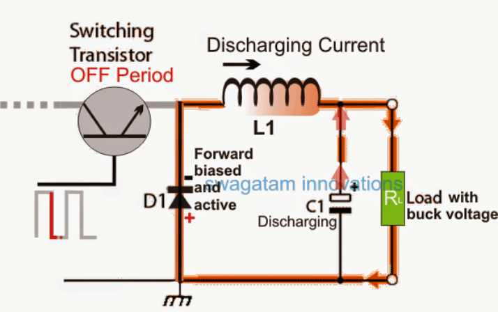
Now referring to the above figure, when the transistor reverts its switching action, that is as soon as it's turned OFF, the L1 is yet again introduced with a sudden void of current, to which it responds by releasing the stored energy towards the load in the form of an equivalent potential difference.
Now, since the T1 is switched OFF, the cathode of D1 is relieved from the positive potential and it's enabled with a forward based condition.
Due to the forward biased condition of D1, the released L1 energy or the back EMF kicked by the L1 is allowed to complete the cycle through the load, D1 and back to L1.
While the process is being completed the L1 energy goes through an exponential drop due to the load's consumption. C1 now comes to the rescue and assists or aids the L1 EMF by adding its own stored current to the load, thereby ensuring a reasonably stable instantaneous voltage to the load...until the transistor switches ON again to refresh the cycle back.
The whole procedure enables the execution of the desired buck converter application wherein only a calculated portion of the supply voltage and current is allowed for the load, instead of the relatively bigger peak voltage from the input source.
This may be seen in the form of a smaller ripple waveform instead of the huge square waves from the input source.
In the above section I have explained exactly how buck converters work, in the following discussion we'll delve deeper and learn the relevant formula of determining the various parameters related to buck converters.
Formula for Calculating the Buck Voltage in a Buck Converter Circuit
From the above decision we can conclude that the maximum stored current inside L1 depends on the ON time of the transistor, or the back EMF of L1 can be dimensioned by appropriately dimensioning the ON, and OFF time of L, it also implies that the output voltage in a buck converter can be predetermined by calculating the ON time of T1.
The formula for expressing the buck converter output may be witnessed in the below given relationship:
V(out) = {V(in) x t(ON)}/T
where V (in) is the source voltage, t(ON) is the ON time of the transistor,
and T is the "periodic time" or the period of one full cycle of the PWM, that is the time taken for completing one full ON time + one full OFF time.
Solved Example:
Let's try to understand the above formula with a solved example:
Let's assume a situation where a buck converter is operated with V(in) = 24V
T = 2ms + 2ms (ON time + OFF time)
t(ON) = 1ms
Substituting these in the above formula we get:
V(out) = 24 x 0.001/0.004 = 6V
Therefore V(out) = 6V
Now let's increase the transistor time by making t(ON) = 1.5ms
Therefore, V(out) = 24 x 0.0015/0.004 = 9V
From the above examples it becomes pretty clear that in a buck converter switching time t(ON) of the transistor governs the output voltage or the required Buck voltage, thus any value between 0 and V(in) could be achieved simply by appropriately dimensioning the ON time of the switching transistor.
Buck Converter for Negative Supplies
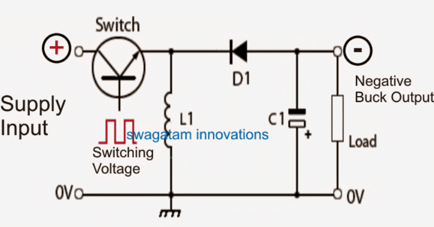
The buck converter circuit I have explained so far is designed to suit positive supply applications, since the output is able to generate a positive potential with reference to the input ground.
However for applications which might require a negative supply, the design could be slightly modified and made compatible with such applications.
The figure above shows that by simply swapping the positions of the inductor and the diode, the output from the buck converter may be inverted or made negative with respect to the available common ground input.


Questions & Answers
sir,there is a video i sent to your Email ,please help me ,i what to know how it works
pro, that's a BIG fake video…there are tons of such fake videos on YT
Hello sir ,
What is the difference between square wave and sine wave inverter.
Thank you so much
Hello Mayank,
square waves are in the form of suddenly rising and falling rectangular or square pulses, while a sine wave is in the form of a slow rising and a slow falling pulses
Hii sir ,
Which inverter is suitable for operating T V and fan.
Thanks
Hi Mayank,
any modified sine wave will do.
I mean square wave inverter or sine wave ?
thank u Mr Swagatam for ur explantion about switching frequency versus output volts. I also wanted u to give us a calculation of how to arrive at the right turns for buck converter with a set frequency sir Alex
Thanks Alex, all those aspects will be covered soon in this site, I have almost sorted everything out correctly.
I have a power supply which outputs 19v 1.5A DC. I want stable 12v 2A DC from the power supply. Is a buck converter applicable for me? If yes, please let me know the applicable switching transistor, Cr and C1.
Thanks Swagatam in advance!
Hi Sribasu, yes a buck converter design would be most appropriate for your need.
for the transistor you can try TIP31C
C1 can be any high value capacitor, you can try the highest value that may be feasible for you to acquire….a 6800uF/25V will do.
The core can be any standard EE ferrite core based assembly
Hello Swagatam. How can i change the output current of a buck converter ? Is there a calculations or what component it vary ?
Hello Ryan, here's one interesting article that you can go through for the solution:
http://www.ti.com/lit/an/slva477b/slva477b.pdf
the page3 provides an effective formula for calculating the max current from a buck design
Hello Swagatam,
I need to make an isolated switching power supply that feeds on the main network of 220VAC and I deliver 12 volt 130 amp, it would be possible to modify an ATX source for you to give me this current, ie one could change the diameter of the wire windings main transformer switched the ATX source mentioned ???
Hello Sebastian, I am sorry I do not have the required info for this….moreover 130amps looks too high and I don't think that may be achievable from an ATX even through modifications
Hello,sir i'm tring to make a bench power supply from an old atx power supply with ltc 3780 is it safe , because the atx can deliver more current then ltc's capable limit ( I'm drive the ltc 3780 with 12v dc from atx power supply) thanks.
Hello tech talker, it's absolutely safe, as as long as the supply to your LTC3780 is within 36V from the ATX….the LTC is internally current controlled and short circuit protected and therefore your buck/boost circuit will be safe.
Thank you very much sir, for the quick response.
please sir , can i get a circuit to reduce 140vdc to 13.28 volt
at what current?
140vdc 5amps. i will use it to charge a 12v lead acid battery,
thanks for your reply.
Sir
I need a code for ardino to produce 30 to 40 khz pwm signal with 50% puls width for buck convertor
Pls hlp
you can try this:
// By Swagatam
void setup(){
pinMode(8, OUTPUT);
pinMode(9, OUTPUT);
}
void loop(){
digitalWrite(8, HIGH);
delayMicroseconds(33);
digitalWrite(8, LOW);
//……
digitalWrite(9, HIGH);
delayMicroseconds(33);
digitalWrite(9, LOW);
}
//————————————-//
Hi Swag,
Thanks for great article. It helped me understand how buck converter works and hopefully it can be my solution. My challenge is the following: I have a power source that provides typical 15VDC (with Vmin of 9.5V and Vmax of 22.5V). Available current is 52mA (with Imax of 60mA). It also says total power output is 500mW.
I need 3.3V out and hopefully able to get up to 100mA. I would also like to estimate what output current I would get if I want to limit the current out of the source to 40mA (as I need 12mA to other stuff).
A TI TPS62177 seems to be able to solve it, however the information available (datasheet, design tool, etc.) doesn’t give me this data.
What do you think?
We are going to use the 3.3V to power 2 Bluetooth Low Energy SoC (nRF52832/840). I hope the switching frequency / ripple on Vout does not disturb the radio chips and messes up the Bluetooth stuff. Is there a topic on this site that discusses this type of issue?
Hi Peter,
If you limit the source current to 40 mA, the wattage would be around 15 x .04 = 600 mW
Dividing 600 by 3.3 gives us 180 mA, considering 90% efficiency would reduce this to 160 mA
Hello Sir.
With regard to your article on Buck Converters. I have a 12 v battery and need to run a picaxe board at 4.5 volts. on my motorcycle. If the 12v input fluctuates i.e drops voltage , will the output stay at 4.5volts please? I understand that the input must be more that the output! I am just thinking if the bike wasnt used for a while and the battery “lost” a little power ( lets say a couple of volts).
Many thanks for a useful artical
Hello Nick, if a feedback based buck converter is built then the output will remain constant for a bigger range of the input. Alternately you can buy a readymade one with a feedback built in.
Sir, what if the input voltage is purely DC and there’s no switching off or on of the transistor and no period of oscillation, how do I calculate the output of the converter?
Engr. Good day sir, please help me, I need a buck converter 24v to 12v/30-50A output … Thanks
Hello Sunshine, you can refer to the following article for all the information:
DC to DC Converter Circuits using SG3524 [Buck, Boost Designs]
Hello. how can I make a very simple DC-DC buck converter without feedback and with an input voltage of 5 volts???
how much should I put the values of the elements?? should I use a drive to start MOSFET??
Hi, you can try the last circuit from this article:
https://www.homemade-circuits.com/calculating-inductor-value-in-smps/
Hi,
I would like to know how to get the periodic time T. Isn’t it the sum of the On time and Of time of the transistor?
Hi, yes periodic time is equal to the sum of ON time and off time of the transistor, and this is explained in the above article.
Hello Swag, well done Sir.
Please, I have a charging system of 100v, 500mA, with high spark but does not charge my 40AH battery, I don’t know the reason.
Please how can I use buck converter to improve the charging system?
Please kindly guide me.
Hello Dayo,
What is the voltage rating of your battery? If it is a 12V battery then you will require a charging current of around 5 amps to charge your 40 Ah battery at 14 V. Your existing charging system has an output power of 100 x 0.5 = 50 watts. Dividing this with 14 gives = 3.57 amps, which is just enough to charge your 40 Ah battery if a very efficient buck converter is used.
For this you will need a 100 V to 14V buck converter circuit….I do not have such a circuit with me right now, so I can’t suggest much about it.
Currently using a 12 VDC source to power 1) an arduino nano chip providing an animated flame effect for a hotel fire, and 2) a buck converter reduced to 3.7 vdc to power a vape coil to generate smoke effect for the fire.
Each time the switch is energized for the smoke circuit, it causes the arduino chip to no longer function.
Is there a means to isolate the source to the two targets?
Since a Buck converter is used, the two systems are already isolated. The issue could be due to a sudden voltage drop across the 12V source. You can try adding a 2200uF capacitor after a diode and supply the output from the 2200uF capacitor to the Arduino. The bigger the capacitor the better will be the results.
If you wish to totally isolate the two systems then you may have to use two separate power supply sources.
lot of thanks for explaining buck converter so easily.
It’s my pleasure…
Sir input voltage is 120V and the DC source is Regulated power supply.
Ok, let me calculate it, I will inform you maybe tomorrow…
Hello Shriraksha,
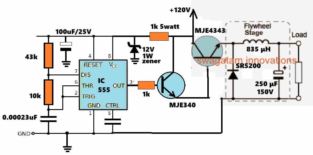
I have designed the buck converter circuit, as required by you, you can check it out below:
43k, 10k are 1/4 watt 5% CFR resistors
1k 5 watt is a wire wound resistor.
100uF is electrolytic capacitor.
0.00023uF is a PPC capacitor, 50V rated
MJE4343 will need a heatsink.
Thank you so much sir. I was not aware that you had replied sir. Sir will l not require inductor in this?
Sorry for this question sir. I figured out in the diagram sir. Thank you once again for your help sir.
No problem Shriraksha, Glad you could figure out the circuit working….
Sir how do we actually calculate the values of the components connected in the circuit? I am curious about the calculations for reference sir.
Thank you sir.
Hello Shriraksha, I have explained the calculations in the following article, you can check it out:
https://www.homemade-circuits.com/calculating-inductor-value-in-smps/
Namaste sir.
Can l use AC adapter of rated 90V-270V for giving 12V input to the buck converter?
Namaste Shriraksha,

Where do you want to supply the 12V? In the following circuit there is no need to supply an eternal 12V. The 12V to the 555 circuit is derived from the 120V input itself.
Sir initially l am deciding to design a buck converter with 12V input. As l am supposed to submit it first sir.
Shriraksha,
In that case you can easily calculate the parameters using the formulas explained in the following article:
https://www.homemade-circuits.com/calculating-inductor-value-in-smps/
You can see a solved example under the heading “Solving an Example Buck Converter Design”…. so you just have to replace the example values with your own values and calculate the exact parts values.
Namaste sir
I am Shriraksha and am a 3rd year btech in electrical engineering student. For my mini project l am informed to design a buck converter using aurdino with output voltage in the range of 100 volts. Please guide me in this regard sir
Thanking you
Shriraksha
Namaskar Shriraksha,
I understand your requirement, however my Arduino coding knowledge is not good, so it can be very difficult or me to help you with this project. You can take the help of “Google Gemini AI”, it can perfectly guide you with all the instructions and codes…
Thank you for replying sir. But is there any possibility of building it without aurdino sir?
Thank you Shriraksha,
Without Arduino it will be much easier.
So the input voltage will be 100V DC, and what will be the output voltage range and maximum current requirements?
Once you specify the above, I will design it for you…
Thank you sir. Output voltage required is 100V/2A. l am not sure about input voltage sir. Please guide me in the process sir.
Hi Shriraksha,
For a 100V output, the input voltage must be higher than 100V, at least 120V DC.
OK sir. Thank you for responding sir. Could you please guide me to build it? How can I start sir? There is no help from the department sir. Therefore l sincerely ask for your assistance. Thank you so much sir.
OK, I will try to design it soon and let you know once it is done…
Thank you so much sir.
Shriraksha,
The input voltage will need to be higher than 100V, so you will have to specify a value for this input voltage, which I can use for the calculations.
Please let me know what DC input source are you looking for, for this project?
Hello sir, please can you help with buck converter circuit for 150v/500mA to 24v. Hope for a favourable response.
Hello Atinuke, you can take the help of these two articles:
https://www.homemade-circuits.com/calculating-inductor-value-in-smps/
https://www.homemade-circuits.com/buck-converter-calculator/