Driving a three phase motor on a single phase supply directly through ordinary methods can be difficult and dangerous. It requires accurately designed circuits for implementing the operations. Here I have tried to present one such PWM controlled three phase motor driver circuit. I have explained more.
The circuit can be understood with the following points:
Circuit Operation
Before going to the following explaination it would be important to know regarding a three phase signal generator circuit explained here: https://www.homemade-circuits.com/2013/09/three-phase-signal-generator-circuit.html
The above circuit becomes the crucial part of the whole design because it's this stage which provides the 120 degree phase shifted signals for driving the proposed 3 phase motor driver stages from a single phase source.
All the involved circuits are operated from a common 12V DC source which may be obtained from a standard AC/DC adapter configuration using a 12V transformer, bridge and capacitor network.
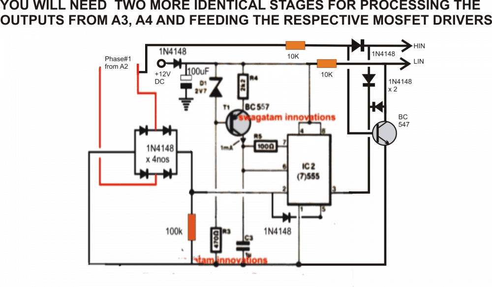
In the first diagram shown below we see a simple 555 PWM generator circuit which generates equivalent modified sine wave PWM waves at its pin#3.
These are generated in response to sine waves from the outputs of the 3-phase signal generator circuit as explained in the above given link.
That means we would require three such identical 555 PWM generator stages for processing the three outputs from the 3-phase signal generator opamps.
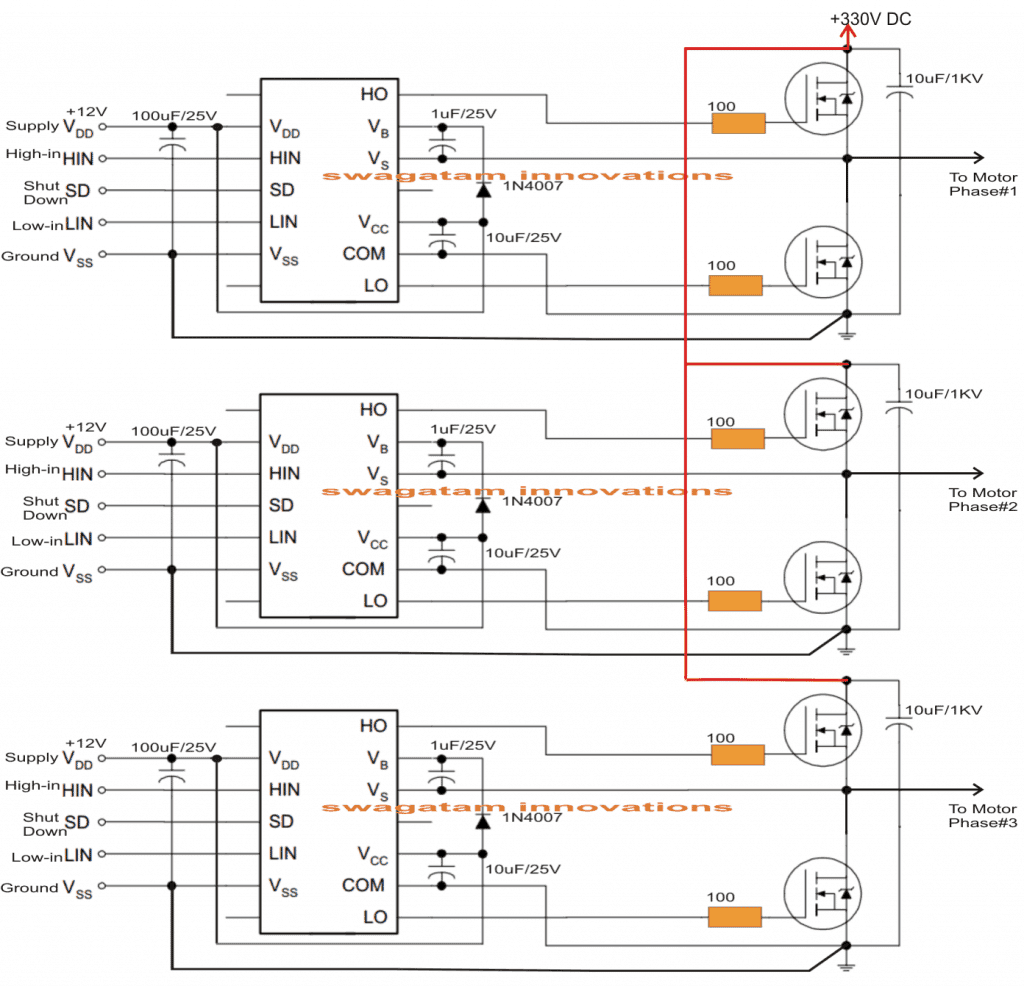
The outputs from the respective three PWM generators as referred HIN and LIN are fed to the inputs of three discrete mosfet driver circuits, shown in the second diagram below.
We use the IC IR2110 for the driver part of the circuits, three separate IC drivers are used for processing the three PWM outputs from the 555 sections.
The outputs from the mosfets are directly connected with the three wires of the motor.
The 330V to the mosfets is derived by rectifying the mains single phase AC.
Circuit Diagram



Questions & Answers
sir
I can’t understand about (phase 1 A2) which is connect at bridge diode.
Shubhomoy, that A2 signal is supposed to come from a 3 phase signal generator…such as this one:

GOOD MORNING MATE . SEE IF YOU CAN HELP ME.
I WANT TO MOUNT A THREE-PHASE IVERSOR TO RUN A 1.5 HP BLDC TYPE COMPRESSOR MOTOR.
BUT I DON’T WANT TO USE A MICROCONTROLLER,
I WANT TO USE A DEDICATED CIRCUIT THAT DOES NOT REQUIRE MICROCONTROLLER.
CAN YOU HELP ME?
ALMIR
Hi, for driving a BLDc motor, first you will require a BLDC driver circuit, and then a 3 phase inverter which can operate the BLDC driver circuit…..all these can be extremely difficult to build and optimize, unless you are an expert electronic engineer, so i will recommend you to buy these units ready-made instead of building it yourself.
swagatham sir i have 48v bldc 800watt (not hub motor) 3phase speed controller. i want 1000w 3phase 48v dc speed controller ckt diagram.
Do you have hall effect sensors in it….?
Hi Mr. Swagatam,
Many thanks for your great work. I did some project like IR2161 SMPS (not only that many projects).
I want to drive and control speed 230V DC brushless(3 phase) motor using Arduino. The motor is Air Conditioner inverter motor. I saw many article of yours. I wonder if you can give me complete schematic with code. How to connect ‘High In’ and ‘Low In ‘ to Arduino uno. I saw that needs to feedback in some article. Does it need?
Please help.
Thanks Mr. Hemantha, I am not good with Arduino so providing a tested code can be difficult for me, nevertheless I have a related article, which perhaps you can try for your application and check if it works.
https://www.homemade-circuits.com/arduino-3-phase-inverter-circuit-with-code/
its a servo motor and ac motor U V W …it is the same current? or same driver ? single phase line to 3 phase ….
Sorry I did not understand your question properly. If you are referring to a servo motor it’s a lot different than the normal 3 phase motor, so it might require a different driver in my opinion.
Hello
I’ve been fascinated with linear motors since I watched Tomorrow’s World as a kid.
Thus, using a (circa 2-metre) series of 24v solenoid coils I’ve been curious to build a test rig, but have always been stumped at the need for a 3-phase supply. I’ve just come across your ideas – do you think any of them would be suitable for this project?
many thanks
Trevor
Hello, I would need more info regarding the test rig and the solenoids to be able to help. By the way solenoids normally work with single phase supply, they don;t require 3 phase!.
If you imagine a line of (say) 15 solenoid coils: 1,2,3,4,5,6,7,8,9,10,11,12,13,14,15
Using the old UK 3-phase colours, they’d be wired:
R,Y,B,R,Y,B,R,Y,B,R,Y,B,R,Y,B
My understanding of linear motors (correct me if I’m wrong!) that if a steel pin, nail or rod is placed in the core of at least the first 3 solenoids, it will be accelerated along the rest of the solenoid bank to a high speed. Furthermore, by automatically reversing the phases (and larger coils) it could possibly be made into a powerful hammer (?)
I am sorry, I absolutely have no idea about this theory!
Hi Swagatan,
I am a layman in electronics, but I want to make a a simple speed controller board without Arduino for a car alternator as a three phase motor. Please help me make it.
Hi Sidik, what is the voltage level that you wish you use for driving the alternator, is it 12V?
Hi all,
I am not into electronics like you guys. I came on this platform for solution for my 3-phase motor-driven machines. I am kind of stuck with the only available power supply in my area, which is single phase (1 live + ! neutral) mains.
I am presently toying with an idea of driving a 3-phase dynamo with a higher Hp single phase motor.
Please can it work and how do I do it. All wiring stuff is too advanced for me.
Thank you.
Seun, Nigeria
Dear Sir
I m seeking a circuit diagram for single phase submersible motor pump starter/control panel. the circuit required must be made by low cost , easy available components. starter/control panel must contain low voltage/ hi voltage , overload protection, also. can you help me please?
waiting egarly
Shrishail Utagi
Dear Shrishali, please provide the internal working details of the panel…the technical details of all the parts involved in the panel, I’ll try to help
Hello, I have a 3 phase HVAC compressor and my power grid is single phase 220 V , on the compressor label is saying 3 phase at 400V-50Hz / 440V-60Hz 6,3 Amps max
So I need something made for this power requirements and I could not find how big the load can be on this circuit presented on this page ??
I m a electronics amateur at best so I will prefer to buy it ready made if its possible.
Please tell me if you sell this circuit as kit or were I can buy it from.
Hello, sorry I do not manufacture kits so wouldn't be able to sell it to you, but you can easily buy these ready-made from many online stores such as ebay, amazon or alibaba etc.
alternatively you can also try building one with my guidance, it wouldn't be too expensive so there's nothing to worry even if you fail to succeed…
Hello Sir, I want to Make SPWM using p89v51rd2 microcontroller…
I need your help for making circuit of ir2110.
so please…
Rajya, I am not good at coding MCUs, so I won't be able to help you with this project….
but I can help you with IR2110 circuit
Hi, it's for bootstrapping, which makes sure that the high side mosfet always gets a gate voltage that's equal to the drain supply + IC supply voltage(Vdd)
hi sir i really appreciate your great efforts and am in a process of making a vfd driver circuit using this 2110 and with an arduino ….. so can u please give me a hint on this!.
Hi Paul, please specify what info exactly you are looking for??
Hi Sir
.I have a question, what Mosfets used in this project?? thanks.
Hi gh RJ,
you can use IRF540
i need help in this project
hi sir
all component in this circuit plz help me my e mail :[email protected]
yes it's applicable only for AC motors
swagatham sir i want bldc for e bike 48v dc 3phase speed controller ckt diagram 1000watt.
Sreenivasulu, please use the search box above and type BLDC to find the required circuit