• Skip to main content
  • Skip to primary sidebar

Homemade Circuit Projects

Need circuit help? Post them in the comments! I've answered over 50,000!

Blog | Categories | About | Hire Me | Contact | Calculators-online
You are here: Home / Meters and Testers / Make this Digital Temperature, Humidity Meter Circuit using Arduino

Make this Digital Temperature, Humidity Meter Circuit using Arduino

Last Updated on June 8, 2026 by Swagatam 2 Comments

In our previous article, I have explained how to interface temperature humidity sensor with arduino and read out displayed on serial monitor of arduino IDE. In this post I have explained how to display the reading on a 16x2 LCD display for the proposed digital temperature/humidity meter using Arduino.

Table of Contents
  • Introduction
  • Prototype Image:
    • The Design:
    • Program Code

Introduction

This project may be used as room thermometer as well as humidity meter, since both the functionality is integrated into one sensor.

If you haven’t read the previous article yet, please check it out. It covered the basics of DHTxx series sensors.

Now, you know quite a bit about DHTxx sensors. It is better to use DHT22 sensor for projects which you are going to use for long term.

Prototype Image:

Working prototype for a Digital Temperature, Humidity Meter Circuit

The Design:

The connection between LCD and arduino is standard, where you can find similar connection on other LCD based projects.

The program is written in such a way that, you just need to insert the DHT11 into the right port on the Arduino. This will reduce wire congestion during prototyping this project.

If you want to sense the ambient temperature around some area/circuit you may extent the wires from the sensor. So that you’re whole setup may be made inside a junk box and sensor is extended out of the junk box, like a probe.
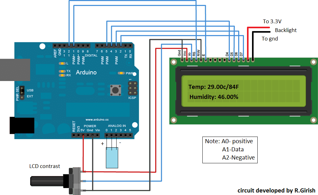
Digital Temperature, Humidity Meter Circuit using Arduino

You can use your favorite Arduino board for this project, but my suggestion is to use “Arduino pro mini” which is less expensive and small in size, which could easily fit into a small junk box for such simple projects.

There are lots of error detection mechanisms written in the DHT library to inform the user about error. But to make the program simple I have just added one error detection mechanism which is illustrated below:
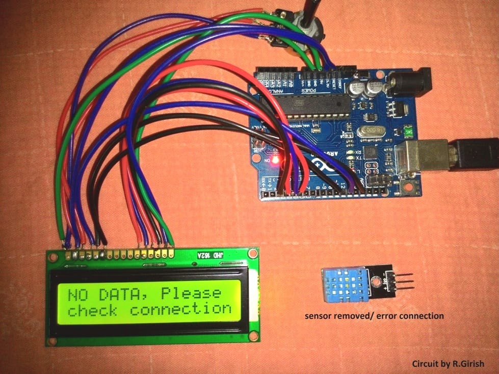
Mostly errors are due to faulty connection between sensor and arduino other errors less likely to occur, since tiny amount of data is transferred between arduino and sensor. This doesn’t mean that other kind of error won’t occur.

To get an idea about all kind of error associated with this sensor, please check out example code in “DHTlib”.

Program code for the above explained digital temperature, humidity meter using Arduino :

Program Code

//------------------Program developed by R.Girish-----------------//
#include <LiquidCrystal.h>
#include <dht.h>
dht DHT;
LiquidCrystal lcd(12,11,5,4,3,2);
#define DHTxxPIN A1
int p = A0;
int n = A2;
int ack;
int f;
void setup()
{
lcd.begin(16,2);
pinMode(p,OUTPUT);
pinMode(n,OUTPUT);
}
void loop()
{
digitalWrite(p,1);
digitalWrite(n,0);
ack=0;
int chk = DHT.read11(DHTxxPIN);
switch (chk)
{
case DHTLIB_ERROR_CONNECT:
ack=1;
break;
}
if(ack==0)
{
f=DHT.temperature*1.8+32;
lcd.clear();
lcd.setCursor(0,0);
lcd.print("Temp:");
lcd.print(DHT.temperature);
lcd.print("C/");
lcd.print(f);
lcd.print("F");
lcd.setCursor(0,1);
lcd.print("Humidity:");
lcd.print(DHT.humidity);
lcd.print("%");
delay(500);
}
if(ack==1)
{
lcd.clear();
lcd.setCursor(0,0);
lcd.print("NO DATA, Please");
lcd.setCursor(0,1);
lcd.print("check connection");
delay(500);
}

}
//------------------Program developed by R.Girish-----------------//

Note: The program is compatible only with DHT11 sensor

You'll also like:

  • transistorSimple Transistor Diode Tester Meter Circuit
  • crystal tester compressedSimple Crystal Tester Circuit
  • function generator circuit10 Useful Function Generator Circuit Diagrams Explained
  • digital panel voltmeter circuitDigital Voltmeter Circuit Using IC L7107

Filed Under: Meters and Testers Tagged With: Arduino, Digital, Humidity, Meter, Temperature

About Swagatam

I am an electronics engineer and doing practical hands-on work from more than 15 years now. Building real circuits, testing them and also making PCB layouts by myself. I really love doing all these things like inventing something new, designing electronics and also helping other people like hobby guys who want to make their own cool circuits at home.

And that is the main reason why I started this website homemade-circuits.com, to share different types of circuit ideas..

If you are having any kind of doubt or question related to circuits then just write down your question in the comment box below, I am like always checking, so I guarantee I will reply you for sure!

Previous Post: « Interfacing DHTxx Temperature Humidity Sensor with Arduino
Next Post: 7 Best Touch Sensor Switch Circuits Explored »

Reader Interactions

Questions & Answers

Total Posts: 2
Newest Oldest
Peter Brownlow
September 1, 2022 • 4 years ago #132837

Hi.
I’m virtually completely new to modern electronics and Arduino, but am interested in constructing the Humidity meter, with the sensor built into a separate remote probe and connected to the Arduino by some sort of flexible lead.
For the remote, is it just a question of using a length of 3 core cable and appropriate connectors, and if so what connectors are available? Is there a restriction on the cable length due to resistance etc? Is a 16 x 2 lcd display a standard item? Any advice on where in the UK to obtain all this stuff, please?
Can you recommend a website for learning the basics of the Arduino and its programming, suitable for a technically minded, reasonably intelligent 75 year old, relative beginner, please?
Any other constructive comments appreciated.
Thanks.

Reply
SwagatamAdmin
September 1, 2022 • 4 years ago #132843

Hi,
You can use a 3 core cable for the sensor, but this cable must be a shielded type cable. Any 3 pin connector will work which can tightly fit into the Arduino connector. The cable length should not be too long, not more than a couple of feet.
All the items shown in the diagram are standard items which can be procured from any good electronic spare part retailer.
Learning Arduino can be long process which will require a lot of understanding of the variables and then a lot of practice through practical experiments.
There are actually plenty of only tutorials that you search an get online.
In this website also there is one such tutorial which you can refer to for gaining some basic knowledge:
https://www.homemade-circuits.com/learning-basic-arduino-programming-tutorial-for-the-newcomers/

Reply

Need Help? Please Leave a Comment! We value your input—Kindly keep it relevant to the above topic! Cancel reply

Your email address will not be published. Required fields are marked *

Primary Sidebar

My YouTube Channel

Circuit Simulator: Draw and Simulate Schematics

circuit simulator image

Categories

  • Arduino Projects (95)
  • Audio and Amplifier Projects (134)
  • Automation Projects (18)
  • Automobile Electronics (104)
  • Battery Charger Circuits (90)
  • Datasheets and Components (109)
  • Electronics Theory (151)
  • Energy from Magnets and Earth (43)
  • Games and Sports Projects (11)
  • Grid and 3-Phase (20)
  • Health related Projects (27)
  • Home Electrical Circuits (13)
  • Indicator Circuits (16)
  • Inverter Circuits (98)
  • Lamps and Lights (161)
  • Meters and Testers (72)
  • Mini Projects (28)
  • Motor Controller (68)
  • Oscillator Circuits (30)
  • Pets and Pests (15)
  • Power Supply Circuits (91)
  • Remote Control Circuits (50)
  • Security and Alarm (65)
  • Sensors and Detectors (107)
  • SMPS and Converters (46)
  • Solar Controller Circuits (62)
  • Temperature Controllers (44)
  • Timer and Delay Relay (51)
  • Voltage Control and Protection (44)
  • Water Controller (37)
  • Wireless Circuits (31)

Subscribe to get New Circuits in your Email

Other Links

  • Privacy Policy
  • Cookie Policy
  • Disclaimer
  • Copyright
  • Videos
  • Sitemap

People also Search

555 Circuits | 741 Circuits | LM324 Circuits | LM338 Circuits | 4017 Circuits | Ultrasonic Projects | SMPS Projects | Christmas Projects | MOSFETs | Radio Circuits | Laser Circuits | PIR Projects |

Recent Comments

  • Michael on Electronic Circuit Projects, Tutorials, and Practical Engineering Solutions
  • Swagatam on 24V to 12V DC Converter Circuit [using Switching Regulator]
  • Swagatam on Automatic Battery Full Cut-Off Latching Circuit with Trickle Charging
  • Ramin on Automatic Battery Full Cut-Off Latching Circuit with Trickle Charging
  • Joss on 24V to 12V DC Converter Circuit [using Switching Regulator]

Social Profiles

  • Twitter
  • YouTube
  • Instagram
  • Pinterest
  • My Facebook-Page
  • Stack Exchange
  • Linkedin

Calculators

  • ZVS Induction Heater + Tank Calculator Tool
  • Zener Diode Calculator
  • Wire Current and Thickness Calculator (Ampacity Calculator)
  • Voltage Divider Calculator
  • Transistor Base Resistor Calculator
  • Transistor Astable Multivibrator Calculator
  • TL431 Calculator
  • Solar Panel, Inverter, Battery Calculator
  • Ferrite Core Air Gap Calculator Tool
  • Parallel MOSFET Calculator Tool: How to Connect MOSFETs in Parallel Safely
  • LC Resonance Calculator for EV Battery Charger Circuits
  • LED String Series Resistor Calculator
  • PFC (Power Factor Correction) Calculator Tool: 3kW
  • Passive Power Factor Correction (PFC) Calculator
  • LM567 IC Calculator Tool
  • SMPS Flyback Boost Converter Calculator
  • Shunt Resistor Calculator for Ammeters
  • SCR and Triac Gate Resistor Calculator
  • Battery Back up Time Calculator
  • Boost Converter Calculator (Non-Isolated)
  • Bootstrap Capacitor Calculator
  • Buck Converter Calculator
  • Buck-Boost Converter Calculator
  • Capacitance Reactance Calculator
  • DCM Flyback Transformer & Wire Gauge Wire Size Calculator Tool
  • Filter Capacitor Calculator
  • IC 4047 Calculator (Frequency and PWM)
  • IC 4060 Calculator
  • IC 555 Astable Calculator
  • IC 555 Monostable Calculator
  • IC SG3525, SG3524 Calculator
  • Inductance Calculator
  • Induction Heater Inductor and Resonant Frequency Calculator
  • Induction Heater Work Coil Calculator
  • Inverter LC Filter Calculator
  • LC Resonance Calculator
  • LED Current Calculator
  • LM317, LM338, LM396 Calculator
  • NAND/NOT Gate RC Values Calculator
  • NOT, NAND Gate Frequency Calculator
  • Notch Filter Calculator Tool
  • Ohm’s Law Calculator
  • Phase Angle Phase Shift Calculator
  • Power Factor (PF) Calculator
  • RC Filter Calculator
  • Reactance Calculator
  • Sine Table Calculator for SPWM Arduino Code
  • Small Signal Transistor(BJT) and Diode Quick Datasheet
  • SMPS Calculator for Toroidal Ferrite Transformers
  • SMPS Flyback Transformer Calculator – Design by Target Duty Cycle
  • TL431 Calculator
  • Op-Amp Hysteresis Resistor Calculator

© 2026 · Swagatam Innovations