• Skip to main content
  • Skip to primary sidebar

Homemade Circuit Projects

Need circuit help? Post them in the comments! I've answered over 50,000!

Blog | Categories | About | Hire Me | Contact | Calculators-online
You are here: Home / Indicator Circuits / Cup Full Indicator Circuit for the Visually Challenged

Cup Full Indicator Circuit for the Visually Challenged

Last Updated on June 1, 2026 by Swagatam 13 Comments

This circuit basically is a fluid level alarm indicator intended for alerting visually impaired individuals regarding the liquid level in a container such as cup, glass or bowl.

Table of Contents
  • Circuit Diagram
  • Circuit Description
    • Using IC 555

The unit can be simply hooked up across the rim of any container with the probes such that it detects the full level liquid in it while the container is being filled, and triggers ON the audible indication.

The container could be a cup, glass, bowl, bottle etc.

The circuit will detect the filling of the cup with any liquid that conducts electricity, such as beer, tap water, tea, milk.
Circuit Diagram
This also means that the circuit will not be able to detect distilled or deionised water.

Circuit Description

The circuit is extremely straightforwad to build and understand.

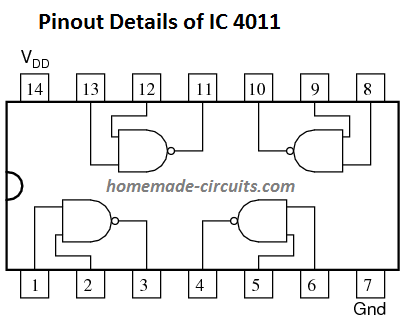
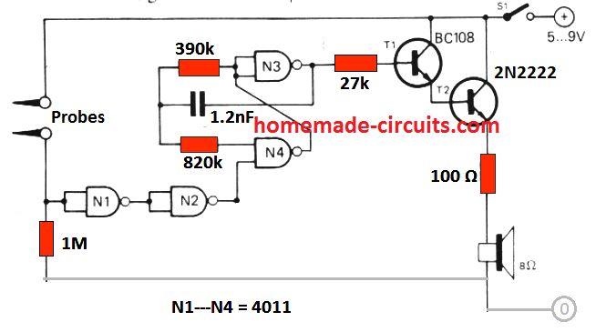
The entire circuit is built around 4 NAND gates using IC 4011.

N1 and N2 are configured as logic inverter/buffer.

With no liquid around the probes the input of N1 is held at a low logic due to the ground 1M resistor. As soon as the probes come in contact with a liquid in the cup or glass the N1 input is instantly pulled high. This causes N1 output to go low, which turns N2 output HIGH, enabling the operation of astable multivibrator N3/N4.

The astable switches T1 and T2 ON/OFF giving rise to an audible warning tone from the speaker.

The frequency of the astable built using N3/N4 gates can be chnaged by tweaking the values of the resistors 820 k, 390 k or the capacitor 1.2 nF. This will in turn help to adjust the tone on the speaker. It can adjusted from a sharp ear piercing tone to a milder buzzing sound, as per the user preference.

Parts List

  • 1M = 1
  • 390k = 1
  • 820k = 1
  • 27 k= 1
  • 100 ohm = 1
  • Capacitor 1.2 nF Disc ceramic
  • Transistor BC108 or BC547 = 1
  • Transistor 2N2222 = 1
  • IC 4011 = 1
  • Battery 9 V PP3 = 1
  • Small 8 ohm speaker 0.2 watts = 1

Using IC 555
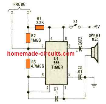
A tiny, cup full indicator circuit could be also created using the IC 555, as shown in the above diagram.

The IC 555 is rigged as an astable multivibrator. As long as the probes are not touching the liquid inside the cup, the astable generates a low frequency 15 Hz clicking sound on the speaker.

When the cup is full, and the probes come in contact with the liquid, the frequency of the astable suddenly increases to 500 Hz sharp tone, which alerts the user regarding the cup full condition.

The speaker could be replaced with the piezo buzzer transducer also, to make the design very compact.

You'll also like:

  • carspeedlimitindicatorcircuitCar Speed Limit Warning Indicator Circuit
  • Block compressedVisitor Counter Circuit Using IC 555 and IC 4026
  • SimpleTemperatureControllerCircuitMake a Simplest Temperature Indicator Circuit
  • Shunt Resistor Calculator for Ammeters

Filed Under: Indicator Circuits Tagged With: Challenged, Full, Indicator, Visually

About Swagatam

I am an electronics engineer and doing practical hands-on work from more than 15 years now. Building real circuits, testing them and also making PCB layouts by myself. I really love doing all these things like inventing something new, designing electronics and also helping other people like hobby guys who want to make their own cool circuits at home.

And that is the main reason why I started this website homemade-circuits.com, to share different types of circuit ideas..

If you are having any kind of doubt or question related to circuits then just write down your question in the comment box below, I am like always checking, so I guarantee I will reply you for sure!


Previous Post: « Regulated Car Battery Charger Circuit for Garage Mechanics
Next Post: Remote Control using Mains Power Line Communication »

Reader Interactions

Questions & Answers

Total Posts: 13
Newest Oldest
U Harsha Vardhan
July 3, 2021 • 5 years ago #92212

Hello! If there is a chance to add led for indication purpose what would be the circuit or the changes to be done?

Reply
SwagatamAdmin
July 3, 2021 • 5 years ago #92215

Hi, You can connect a LED across the N2 output and the ground line, via a 1K resistor

Reply
Harsha Vardhan
July 3, 2021 • 5 years ago #92219

Yeah Thank you!I look forward for your reply.
Can we connect both buzzer and led in the same circuit using IC 4011?

Reply
SwagatamAdmin
July 3, 2021 • 5 years ago #92221

yes you can put an LED in parallel to the speaker, but attach a 470 ohm resistor in series with the LED

Reply
U Harsha Vardhan
July 3, 2021 • 5 years ago #92217

Yeah thanks! But we haven’t used 1K resistor in the circuit using IC4011

Reply
SwagatamAdmin
July 3, 2021 • 5 years ago #92220

1K should be put in series with the LED

Reply
U Harsha Vardhan
June 10, 2021 • 5 years ago #90871

Hii!
May I know the capacitor values for above circuit using 555timer?

Reply
SwagatamAdmin
June 10, 2021 • 5 years ago #90876

C1 = 0.1uF/50V
C2 = 22uF/25V
C3 = 0.01uF/50V

Reply
Gina
June 3, 2021 • 5 years ago #90703

Hi, I am a college student in Korea.

I want you to give me some help about my project.

I am designing circuits for people who is visually impaired. So i am making a cup that can indicate them with sound to avoid water flow.
I want to add buttons so that they can drink the water they want.
For example,
Button 1 pushed—-> when 0.2L water poured, the buzzer is ringing
Button 2 pused—-> when 0.4L water poured, the buzzer is ringing ,,,

I referred to your page “simple water level indicator“ but it is hard to put several buzzers and buttons and remove leds.

I look forward your reply thank you.

Reply
SwagatamAdmin
June 3, 2021 • 5 years ago #90712

Hi, How should the buttons work on the cup? The buttons are supposed to be on the water tank I guess!

Reply
Gina
June 4, 2021 • 5 years ago #90739

I want to control switch(button) depending on water level.
I want to know how to connect switches(buttons) with water level control circuit

Reply
SwagatamAdmin
June 4, 2021 • 5 years ago #90743

In that case we may have to use a timer circuit and a solenoid based water controller. The timer circuit will keep the solenoid switched ON for the specified amount of time which will decide how much water to be dispensed and cut off…

Reply
Željko Kiš
February 15, 2020 • 6 years ago #76630

Maybe take the relay instead speaker,instead 2N2222 some other transistor and circuit will be water tank controller.

Reply

Need Help? Please Leave a Comment! We value your input—Kindly keep it relevant to the above topic! Cancel reply

Your email address will not be published. Required fields are marked *

Primary Sidebar


My Youtube Channel

Circuit Simulator

circuit simulator image


Subscribe to get New Circuits in your Email


Categories

  • Arduino Projects (95)
  • Audio and Amplifier Projects (134)
  • Automation Projects (18)
  • Automobile Electronics (103)
  • Battery Charger Circuits (88)
  • Datasheets and Components (109)
  • Electronics Theory (149)
  • Energy from Magnets and Earth (40)
  • Games and Sports Projects (11)
  • Grid and 3-Phase (20)
  • Health related Projects (27)
  • Home Electrical Circuits (13)
  • Indicator Circuits (16)
  • Inverter Circuits (100)
  • Lamps and Lights (162)
  • Meters and Testers (72)
  • Mini Projects (28)
  • Motor Controller (68)
  • Oscillator Circuits (28)
  • Pets and Pests (15)
  • Power Supply Circuits (91)
  • Remote Control Circuits (50)
  • Security and Alarm (65)
  • Sensors and Detectors (107)
  • SMPS and Converters (45)
  • Solar Controller Circuits (61)
  • Temperature Controllers (43)
  • Timer and Delay Relay (50)
  • Voltage Control and Protection (44)
  • Water Controller (37)
  • Wireless Circuits (31)


Other Links

  • Privacy Policy
  • Cookie Policy
  • Disclaimer
  • Copyright
  • Videos
  • Sitemap

People also Search

555 Circuits | 741 Circuits | LM324 Circuits | LM338 Circuits | 4017 Circuits | Ultrasonic Projects | SMPS Projects | Christmas Projects | MOSFETs | Radio Circuits | Laser Circuits | PIR Projects |


Recent Comments

  • Swagatam on Pure Sine Wave Inverter Circuit Using IC 4047
  • Johan on Pure Sine Wave Inverter Circuit Using IC 4047
  • Swagatam on DPDT Relay Working, Pinouts, Testing Explained
  • Swagatam on How to Modify SMPS for Adjustable Current and Voltage Output
  • Swagatam on Pure Sine Wave Inverter Circuit Using IC 4047

Social Profiles

  • Twitter
  • YouTube
  • Instagram
  • Pinterest
  • My Facebook-Page
  • Stack Exchange
  • Linkedin

© 2026 · Swagatam Innovations