In the following post I have explained a very simple circuit idea which can be used for controlling a motor's rotational direction i.e. for moving it either clockwise or anticlockwise through alternate miss calls from your cell phone.
The Circuit Concept
I have already discussed a novel cell phone controlled remote switch circuit where the unit can be used for switching an electrical gadget through the users cell phone. The user just has to call the remote system which responds to the blank calls and generates the required alternate switching of the connected gadget.
The same circuit has been used here also, the output is appropriately modified such that now the unit becomes suitable for toggling the rotation of a DC motor.
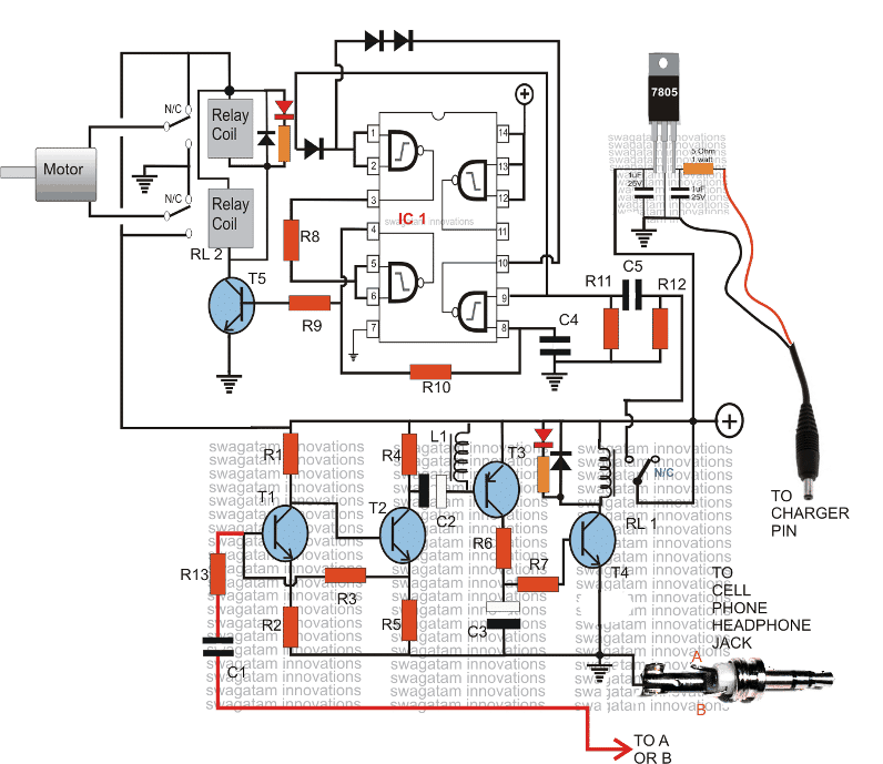
The circuit shown below can be used for controlling a motor rotational direction, let's try to understand it's functioning details:
The lower section of the diagram consisting of T1, T2, T3 and T4 along with the associated components forms a simple high gain audio amplifier circuit.
This circuit is used for amplifying the ringtone generated by the attached modem cell phone unit.
How it Works
The modem cell phone handset is an ordinary NOKIA 1280 cell phone which is permanently integrated with this circuit.
The above modem cell phone uses a prepaid SIM card and thus it becomes a self contained receiver module.
When this modem cell phone is called by the owner's cell phone, its ringtone activates and gets amplified by the above explained tone amplifier stage.
The amplified signal becomes powerful enough to triggers the relay RL1.
This relay holds or remains activated as long as the call stays connected, and breaks when the call is disconnected.
RL1's N/O contact is supplied with a 12v trigger to the adjoining stage which is a FLIP/FLOP stage, made by using four NAND gates from the IC 4093.
With every alternate missed calls from the owner's cell phone, the modem cell phone signals the tone amplifier, which activates RL1, and RL1 in turn flips or flops the IC1 circuit.
The output of the flip flop is connected with a relay driver circuit which is attached with two relays RL2 in parallel. You may use a single DPDT relay also for better convenience.
The contacts of the relays are configured in such a manner that flipping them produces opposite movements for the motor that's integrated to them.
The mains supply to the relay and the motor is taken from RL1, which means the motor flips with every subsequent "missed calls" and remains activated until the call stays connected, and then halts.
The circuit can be modified in many different ways as per the users specifications.
The modem cell phone should be appropriately assigned with a particular continuous ringtone while the default ringtone should be assigned to "empty", tis will make the unit immune to unknown numbers or wrong numbers, and the owner will be the sole controller of the attached circuit and the motors.
Parts List
All resistors are 1/4w 5% CFR unless otherwise stated.
- R1 = 22k
- R2 = 220 OHMS
- R3,R11,R12 = 100K
- R4,R6,R7,R9 = 4.7K
- R5 = 1K,
- R8 = 2.2M
- C1,C4,C5 = 0.22uF DISC TYPE
- C2,C3 = 100uF/25V
- T1,T2,T4,T5 = BC 547B
- T3 = BC557 B
- ALL DIODES = 1N4148
- IC1 = 4093
- RL1 = RELAY 12V/400 OHMS SPDT
- RL2 = Relay DPDT 12V/400 ohms
- L1 = small buzzer coil, small choke or similar.
- JACK = 3.5mm AUDIO JACK
- CELL PHONE MODEM = NOKIA 1280


Questions & Answers
what is the rating of the motor could be operated by this circuit
Hi looking for an phone that can activate large motor please advise
It depends on the relay contact rating, in the above diagram any motor up to 500 watts can be used
12 v battery ,, there’s an few motor 2 on wheels 2 on steering, 1 on hydraulic pump for arm,, and 1 on grab attachments light motor,, it has lights and cameras
Sorry, currently I do not have this circuit that would control motors through mobile phone commands.
Sir I want to make you help me
For that may I know your contact number
Sir I want to make a wireless 3 phase mobile starter for agricultural purpose ….and I'll use for projects also…Sir plz…give me its ckt ingo and its ckt components details…..and how to design it
Pankaj, you can do it with an Arduino circuit as shown below:
https://www.homemade-circuits.com/2017/04/gsm-water-pump-controller-with-call.html
replace the relay with a TPTT or triple contact relay for the 3 phase control
Sir I need only motor on and off circuit board
Price tell me which bank transfer
Thank you sir
Rasek, sorry I don't sell materials in this website, but i may start soon…
can u please say me how to connect DPDT relay in this circuit ……. I dont know how to connect DPDT relay…. can u please explain about it
.
RL2 RELAY 15SEC KE BAAD OFF HOTA HAI
Hello sir
1st miss call dene ke baad relay quickly on hota hai but 2nd miss call dene ke baad 15sec.ke baad relay off hota hai
R12/C5 ka joint ko manually positive par bar bar touch kar ke deknho, RL2 ON/OFF hota hai ki…
kaun sa relay RL1 ki RL2
R9 aur R7 ke series mein LED fix karo, yeh batayega kaun sa transistor ON reh jata hai
Ok
can i use 1 12v battery to power the circuit
yes you can
is it the same if i want to trigger the motor using phone's alarm?
yes it's possible…., but how can you trigger the alarm through a missed call??
how about using 555 in bistable mode?
555 bistable will require two relays….
it will require relays, we have only one one relay in the above design
Sir. Can I build this circuit by replacing cd4093 with ne555. Is there any way to modify it so that I can use a available part ne555.
Shiva, IC555 cannot be used as a flip flop…it can be toggled ON for sometime but after that it will switch OFF automatically.
Is this circuit can be available in market?
hi.. How can i use above circuit to start and stop small dc motor.. where do i connect motor? do i need any other additional components? can any other phone can be used other than nokia 1280. Thank you..
thanks, so you mean to say that you are not able to figure out how to make the relay contacts operate a motor?? I am sorry then you must first learn all the basics and then come back here, because this project could be far too complex for any any newcomer.
the relay contact has to operate from N/C to N/O for the motor to work…
Hi. Thanks for clearing confusion. I did as u said but it dint work. I have connected positive 12v supply to one end of dc motor and other end of dc motor to relays normally open terminal and I have grounded the common terminal of relay is this the correct connection? And how can I debug my circuit?
without DC input how would the motor get its supply??
the polarity can be anyway round, depends which way you want the motor to rotate anticlockwise or clockwise.
Hi. Is dc input is mandatory? Or can I directly connect two wires of motors to normally open pin and common pin relay will that work? If not any polarity is to be taken care while connecting dc input and motor. Thanks in advance
Hi, you just have to replace the "AC input" with a DC input and the "load" with your motor
hi. i have checked the above link you specified but i am bit confused where and how to connect dc motor it would be very useful if you could tell me that. Because i am confused with the AC main supply in that circuit and load because dc motor does not require any ac supply as per my knowledge. if you could tel me in very perticular where to connect the motor. Thanks in advance.
Hi, you can refer to the following article for your specific application
https://www.homemade-circuits.com/2012/01/how-to-build-gsm-based-cell-phone.html
no modifications would be required.
you can use other cellphone also which may have identical features to the recommended NOKIA phone
i need , 0 to 100 pounds adjust string tension dc12v motor control circuit.please sir.
Thanks you very much, I want control my water pump ( motor) in my farm can it possible that this circuit,
yes that's possible
Ok …Thank you so much sir…
Ok Sir..thank you…
And if we give missed call for switching OFF the AC motor ,then will it fully stop or continue its rotation in opposite direction…?
It will fully stop the motor.
Sir, I mean to say how to select components that is capacitors, relays,resistors,transistors,IC etc…
all are standard parts, nothing is specially rated..for example all resistors are 1/4 watt, all capacitors are as per 12V supply etc….only the TPTT relay will need to be rated as per the motor current specs.
Thank you sir…And one more question is that, Is there any design basis for this circuit?
If yes, then can you tell me that in detail with design steps also?
Plz send me on my email- swatilife123@gmail.com
Swati, sorry I did not understand what you meant by design basis….you will have to replace RL2 with a 3 contact relay or a TPTT relay in the above circuit for controlling a 3 phase motor.
Hello Sir…I want to switch ON & OFF AC 3 phase motor…
Is this circuit suitable for my requirement?
And if there are any changes in this circuit ….
Plz tell me as early as possible…
Hello Swati, yes the above circuit can be used for the purpose, the upper two relays will need to be replaced with a single relay having three sets of contacts which can be then wired across the three wires of the motor and the AC inputs
Hello Sir…I want to switch on & off AC 3 phase motor with every subsequent missed calls. Is this circuit suitable for my requirement?
And if there are any changes in the circuit..
Plz tell me as early as possible….
Sir please upload a block diagram of control a lamp by missed call aystem
Sir I want Controlling Motor with a Cell Phone -ful Circuit Diagram
Please explain the application clearly, elaborately and in good English….
Dear Swagatam,
Can you publish a circuit to control AC motor with cell phone.
thanks
Dear Chandan, yes it can be done by using DTMF technology, however I don't like the concept because it consumes your cellphone's "talk time" and therefore the procedure is never free of cost.
hai sir i need to know how to control electricity in house to reduse electricity bills. plz give me an idea with circuit diagram
use all the equipment wisely…for example use TV sets with less contrast, use fridge at lower cooling adjustment, same with ACs and fans….you will see 50% reduction in the bill..
thanks for your valuable reply. i got it what you are saying but i want to connect this circuit to the 3 phase motor starter so that im able to on off motor connected to starter..
if you have a starter with your 3 phase motor then you wouldn't require the upper 4093 flip flop stage, you can simply connect RL1 contacts in parallel with the starter switch.
make sure that you end the call immediately as soon as the motor starts, so that the supply is fed only momentarily to the starter relay.
hi swagatam im your big fan..shall i use this circuit to on off three phase motor.?
thanks Vinod, yes you can use the above circuit with 3phase motor, ignore the shown relay contact set up for the motor, for your application you will need to use a relay with 3 changeover contacts, or TPTT relay and simply connect all the 3 contacts in series with the motor wires and the 3 phase mains input.
Sir I use of CD4093 but my relay 2 always on or no turn off
go through all the comments above…you may get a clue
hai ,
I want more explanation about ON/OFF cycle ( What I meant is whether the motor will sustain for ON for long . How it is controlling the ON/ OFF. There is no explanation for IT.) From the explanation what I understood is the motor will be working only during the ringing period of the mobile .It will be sustain only for few second .
Thanks
Sreelal
The motor will run either clockwise or anticlockwise alternately, in response to the toggling of RL2….the motor will not stop until power is switched off.
hello nokia 200 is best
Sir
Thnks for givng the ckt. I did assembled this.
I got first stage, bt i can't get second flip flop stage,it's not done..pls give me a suggession.
Please see the second circuit from this link, it's the same as the above 4093 stage, this will help you to compare the stages and troubleshoot:
https://www.homemade-circuits.com/2011/12/build-these-simple-flip-flop-circuits.html
Mr. Swag I have made modification changing RL2 to I.C. 555 it work fine now, Thankyou
OK thanks.
Hi sir its been 5 days since I have carefully doing this project and checking it carefully RL1 runs really smooth and has no problem at all, but RL2 has really giving me a big problem, sometimes relay works fine sometimes it wont, if I`m correct R11 and R12 are full down voltage resistor isn't it?, I also change IC 4093 4 x just guessing that this has factory fault but still same problem giving me, I have carefully double check my layout before posting here, but RL2 really dont work properly, what might be the problem of this?, I really do hope to finish this project, can you help me check the circuit diagram what probable cause we are having now, cause lot of us has the same problem running RL2 and regarding RL1 it is running well.. Thank You So much, more power to you..
OK thanks, R11/R12 are for discharging the center capacitor so that the circuit can be initiated every time quickly
Ok Mr. Swagatam I`ll do it right away Thanks for the help, more power to you.. BTW Full down was wrong I mean pull down, sorry missed type it 🙂
…once confirmed it may be integrated back with RL1.
Hi Jerry,
Make the RL2/4093 circuit separately and test it manually by triggering its input with positive pulses, you may refer to the following diagram for better understanding:
images.brighthub.com/8c/2/8c241a49a602156dd8edcb98e3826680a7c332b2_orig.jpg
yes…
can we use opamp to amplify ?? here what is the purpose of nand gate ic…???
opamps wont work, nands are for generating On/OFF or flip flop actions on RL2
it is compulsary to use nokia 1280…???
i tested it on 1280 and therefore recommending it.
in my circuit i think the tone of the phone is not amplified upto that level required for the circuit.
use NOKiA1280, in the "assign tone" use any musical tone instead of the suggested "beep once" tone
sir,i am not understanding the usage of phone…please help its urgent..
Please read the bottom section of this article, it's comprehensively explained here:
https://www.homemade-circuits.com/2012/01/how-to-build-gsm-based-cell-phone.html
thanku for the replies…
does the motor is affected by the volume of the tone of the phone cum modem.??
The mortor has no connection with the modem, you can clearly see that the motor wires join with the positive/negative supply via the relay contacts and no connection with the modem.
yes sir i have given ground..i have connected the motor to the common terminal of both the relays is this correct ??
yes ia have given ground to them..i have connected relays to the common terminal of both the relays…is this correct?
sir, in this ckt the two led which are connected to the relays are glowing but the motor is not rotating.what is the meaing tha the led's are glowing and relay is also producing sound that means it is also working but motor is not rotating.there is some error in this circuit?please help its really urgent.
The diagram correct, in the shown position the (+) passes through upper relay N/C into the motor and comes out of the motor to pass through the N/C of the lower relay to (-), in this condition the motor will rotate in one direction,
now if the relay is activated, the opposite will happen and the motor will rotate in the opposite direction.
Did you connect the N/C and N/O of the two relays to ground(-) as shown in the diagram??
we have to
use 2 relays in relay 2 ckt..??
yes, two relays are used in the upper section, relay coils connected in parallel.
we can't use any other phone…..??
for the modem?? yes, if it includes an assign tone facility.
Dear swagatam,
i am trying to build 1st part of this circuit only but not able to toggle that relay i am building only that area which includes relay, IC 4093, BC547B & etc i didn't build receiving section but not able to understand which wires has to get sorted to trigger the relay. i tried to sort wire coming from R12 with positive wire of the supply but it didn't worked. please help me out ASAP
Thanks in Advance
Dear Ankit,
I would like like to repeat my answer which I did in your previous comment, touch the positive momentarily with the point that is going to the relay RL1, as you touch and release it T5 relay will switch ON/OFF alternately.
your previous comment was answered here:
https://www.homemade-circuits.com/2011/12/build-these-simple-flip-flop-circuits.html
No, speaker signal from cell phone is not negative based, here we require negative based signal, meaning one terminal should connect with the negative of the supply.
R10 = 2.2M
R13 = 100 ohms
hello sir,
are the relays DC or AC?
DC