In this article I have explained how to make a low cost yet fully automatic hand sanitizer dispenser circuit which will allow a touch-free or contactless dispensing of the sanitizing liquid on the user's hands.
This contactless hand sanitizer circuit facilitates the user to access the sanitizing liquid on hands automatically without the need of operating or touching the sanitizer bottle pump manually. The feature ensures that viruses have no chance of spreading through physical touching of the sanitizer bottle and its operating parts.
However, to be automatic, the system will require some kind of sensor to detect the presence of a human, or a human hand under the dispenser unit.
For this we employ the most basic human sensor unit which is the PIR, or a passive infrared device.
Basic Working Details
A PIR is designed to detect the infrared heat from human body and produce a corresponding electrical pulse at its output pin.
This pulse is used for activating a one-shot timer based relay driver stage which activates the relay momentarily, and powers a spring loaded solenoid.
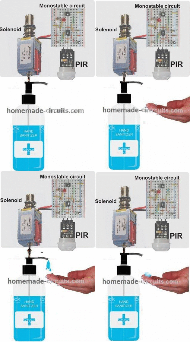
The solenoid pushes the pump shaft of a sanitizer bottle to dispense the liquid in the hands of the user. The concept can be visualized in the following image.
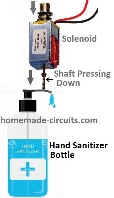
The solenoid in the above image is connected to the output of a monostable circuit.
A monostable circuit is a configuration which causes a momentary high output in response to a momentary input trigger. The output stays high for a predetermined fixed period regardless of the input trigger duration.
In this automatic sanitizer dispenser circuit the monostable is triggered by a PIR as soon as an approaching human hand is detected by the PIR.
The monostable in turn activates the solenoid for some moment of time as determined by its RC timing components.
The activation of the solenoid causes its central spindle to quickly push and pull in the vertical direction, pressing the pump handle of the sanitizer bottle once.
This eventually causes the bottle to dispense the sanitizing liquid into the hand of the user.
Once the user withdraws his hand from the system, the PIR shuts down, and the monostable also deactivates the whole system, until another user brings his hand in the range of the PIR to repeat the procedure.
The monostable triggering circuit for the proposed automatic hand sanitizer dispensing unit can be designed using transistorized monostable or through a popular IC 555 based monostable circuit.
We will discuss both the variants in the following discussions:
Transistorized Hand Sanitizer Dispenser Circuit
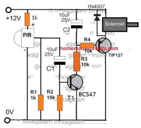
The transistorized version of the circuit looks very straightforward. When the PIR device detects a human intervention, it conducts and sends a pulse to the base of T1 via C1.
The current through C1 instantly activates T1, which in turn activates T2 and also the solenoid pump.
In the meantime, C1 quickly charges and prevents the entry of any further current to the base of T1, thus blocking the repeat DC pulses from the PIR output. This ensures that the system works only momentarily for each detection, and then shuts down until the hand is removed and a fresh cycle is initiated.
This one-shot activation of T1/T2 ensures that the connected solenoid load activates to generate a single push-pull action on its magnetic spindle.
The spindle operates the sanitizer pump handle to dispense a single dose of the sanitizing liquid on the user's hand.
You can notice that the solenoid is connected at the emitter side of the transistor, instead of the regular collector side. The emitter connection actually ensures that the solenoid activates with a gentle soft-start pushing in response to the charging of the 10uF capacitor C2.
If it is connected at the collector side would result in the solenoid being pushed with a sudden thrust, which might not look very impressive.
Simplifying the above Design
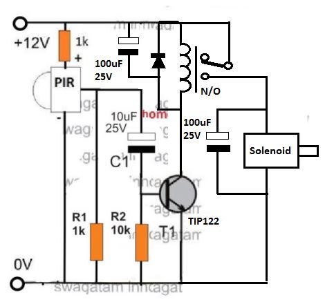
The above transistorized contacless hand sanitizer could be further simplified by using a relay as shown in the following design:
Using IC 555
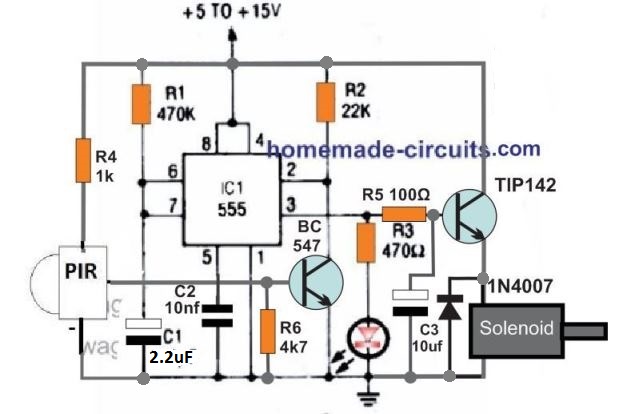
The figure above shows a standard IC 555 monostable circuit. Here, when pin2 is grounded, causes the output pin3 to go high for a period decided by the R1, C1 values or their product.
In this automatic sanitizer dispenser design the R1, C1 is calculated to produce an approximately 1 second output high, in response to a low signal at pin2.
When the PIR detects a human hand, it conducts and switches ON the BC547 transistor which in turn triggers the pin2 of the IC.
This instantly causes the pin3 to go high and activates the TIP142 transistor and the connected solenoid, generating a 1 second long push and then a shut down pull-up on the solenoid shaft.The pull is generated by the attached spring tension on the solenoid shaft.
Again, in this version also the solenoid can be seen connected at the emitter side of the transistor in order to enable a soft thrust on the solenoid shaft depending on the charging response of C3.
An animated view of the whole system can be visualized in the following GIF image.
Infrared Reflective Sensor TCRT5000
Since PIR is a relatively expensive sensor, a cheaper alternative for making an automatic hand sanitizer could be by using the IR reflective sensor TCRT5000.
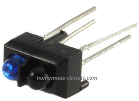
The sensor is a simple combination of an IR photodiode transmitter and IR photo receiver packed side by side, inside a single package as shown below:
The characteristics of this proximity IR sensor module can be understood from the following data:
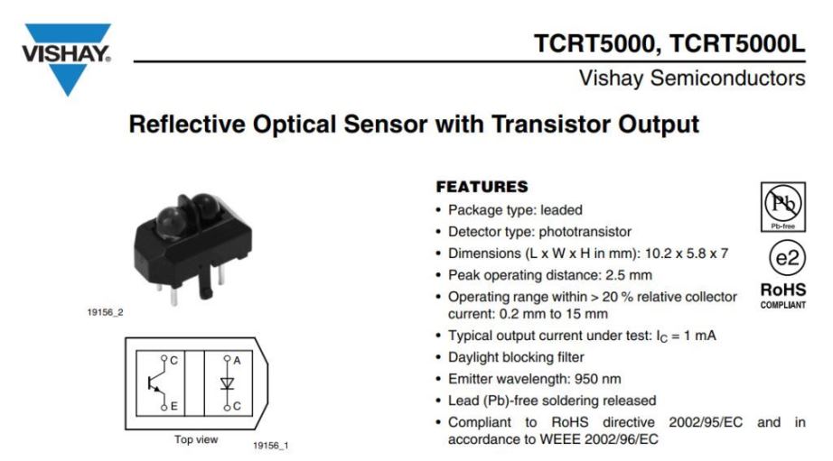
From the internal layout diagram of the sensor we can clearly see that the module consist of a photodiode which emits the IR signal towards the target, and an adjoining phototransistor receiver which is positioned to receive the reflected IR signal from the target.
To adapt the sensor in an automatic hand sanitizer machine, we can yet again implement our work horse IC 555 based monostable, a shown below:
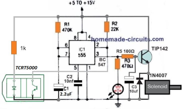
The circuit is quite self explanatory, but if you have problems understanding the details, you can always feel free to use the comment box below for initiating a discussion.
Using HC-SR04 and IC555
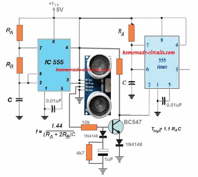
The circuit shown above can be used for implementing an automatic sanitizer dispenser through the ultrasonic proximity detector module, HC-SR04, and a couple of IC 555 circuits.
The left side IC 555 is configured as an astable multivibrator while the right side IC 555 circuit is wired as a monostable multivibtator.
The astable RA, RB, C components values must be calculated to enable a 10us ON and 60us OFF PWM from pin3 of this IC.
The RA and C timing components of the monostable must be adjusted to produce a 1 second high one-shot output from pin3 of this stage.
This output could be used for powering the dispensing pump, motor, solenoid etc as per the requirement of the design.


Questions & Answers
Hello Sir,
This is Usama Asif. This Website is really made a great effort for us. Sir I just need some more details and Calculations about first circuit(through Transistors) of Automation Hand Sanitiser.
Hope to get response immediately.
Thanks!
Thank you Usama, the transistor base configurations are simple RC circuits, which switches ON the respective devices when the charge reaches 0.7V value.
You an read more about RC circuits here:
https://www.homemade-circuits.com/how-rc-circuits-work/
Hi sir! i’m one of your innovation follower from ethiopia. please can you tell me the specifications of the PIR and solenoid so as to order them from stores?
with respect!
Thanks Habtamu, the PIR can be any small PIR like the one shown below
The solenoid will need to be experimented to ensure it has sufficient power to push th sanitizer pump deep down. According to me a 12 v 2 amp solenoid should do the job well.
How to replace pir sensor with ir sensor like tcrt5000???
I will try to update the design soon in the above article.
Can we use 1st circuit with 5v power supply?
yes, if the solenoid is also 5 V rated
I tried the pir circuit it’s turns on as I plug in without connecting pir and stays on
Even if their is no connection between R4 & base of bc547
R4 is at the base of TIP127, please do it only if you know the basics of electronics.
without base bias the TIP127 cannot turn on, please check your transistor or replace it with a new one.
The monostable 555 using tip142 circuit bro with timer ic using pir sensor not the first one ,it turns on without sensor trigger it’s kind of important please help me out
Thank you
Without R4 a positive voltage cannot reach the base of BC547, so BC547 cannot conduct. With BC547 not conducting pin2 of the IC cannot be grounded and the monostable cannot be triggered. You can do one thing, first confirm how the BC547 is getting triggered? Alternatively, you can connect a 1uF or 2.2uF capacitor parallel with R6 and see if this solves the issue
This is really nice. I am a mechanical engineer and made one using Transistor (PNP), IR sensor and Sebmercible water pump and connected to 6V supply. But batteries get drained in a week. Any suggestions?
Thank you for liking the project. Any form of motor or solenoid will require a significant amount of current to operate which can drain any battery quickly, if you want the battery to last long make sure the battery is a li-ion battery, with Ah rating 5 times higher than the pump.
Thank you very much Sir for your time and response. My self being a mechanical engineer, may of the terms go out of my head. I am sorry for silly question. The water pump I used is 3-6V DC submersible pump. How do I find Ah rating for that? And with consideration of IR sensor and PNP transistor voltages, can you guide me for an appropriate battery set please. Thank you for your time and guidance. I am enjoying your site with so many innovations, and trying to learn basics now. Thank you again for your time.
Thank you Shekhar, is the motor a small white colored one which is available from amazon, flipkart etc. If it is, then its current consumption is somewhere around 200 mA, which means the battery should have an Ah rating of 1 Ah, and the battery should be a 3.7 V 1 Ah Li-ion battery, the one which are normally used in small mobile phones. The IR sensor is not relevant to the load, it can be any standard photodiode. for the transistor you can use a BD140 transistor or a 2N2907
Thank you very much sir. Yeah, i bought pump from Amazon. I will try to connect again with your recommend battery capacity and keep you posted. Thank you very much for your help and guidance. When your time permits, if you can teach on the calculation part to determine 3.7V 1 Ah battery, that will be great. Thank you again for all your help and guidance.
One point puzzles me is, I used 4 X1.5V AA Duracell batteries giving 6V and it has 2.6Ah. and your suggestion is to use 3.7V 1Ah, which is less than what I did use. So how does this works better?
And since pump uses 200 mA, using 2.6Ah AA batteries, shouldn’t the circuit work for at least 10 days? Why did batteries drained in 4 days? Sorry for my silly question.
Hi Shekhar, alkaline battery and Li-Ion battery work on different principles. Li-ion can withstand higher discharge rates than any other standard forms of batteries, while alkaline batteries cannot withstand high discharge current and may start degrading quickly, causing lower efficiency results.
At 200 mA continuous discharge your alkaline battery should last for 10 hours, not 10 days. So for intermittent use, 4 days back up looks quite OK to me.
Thank you very much sir again for your time and guidance. I understand now. I will try to work on my connections again & I will check how do I connect 3.7V 1 Ah battery & I may have to figure out rechargeable option for this? I will explore more in Google . Thank you for all your time and help. I am learning while I am working on these and your guidance is awesome. In case if I want to reach out to you for any further questions on any of the hobby projects I do or guidance or if I want to share the circuit for your suggestions, how do I do? This is all I started as a hobby with Arduino, therefore my basic knowledge is minimum. Again , thank you for everything and stay safe.
No problem Shekhar, I’ll try to help as far possible, for external diagrams you can upload them to any external free image hosting site and provide the link to me, I’ll try to solve it for you.
Thank you Sir. Have a great evening and stay safe. I feel lucky to find your blog. Thank you for all your guidance.
Thank you Shekhar! You too stay safe!
HOW CAN WE USE 3.7V BATTERY FOR THE 555 TIMER AS ITS INPUT VOLTAGE RANGE IS MIN 4.5V.
I HAVE A 18650 LI-ION RECHARGEABLE BATTERY (3.7V 2200mAH) ALONG WITH TP4056 CHARGE/DISCHAGE PROTECTION MODULE. HOW CAN I USE THIS BATTERY WITH THIS CIRCUIT? SHOULD I USE A DC-DC BOOST CONVERTER?
ANY ADVICE/SUGGESTION WOULD BE GREAT.
THANKS
You can use an LM555 which is a CMOS version and works with 3 V also
https://www.homemade-circuits.com/cmos-ic-lmc555-datasheet-works-with-1-5-v-supply/
but make sure the solenoid also is rated at 3 V, and connect the solenoid at the collector side of the transistor, not on the emitter side.
I AM USING 3V PUMP SO THAT WILL DO THE JOB I GUESS
BUT HOW DO I TELL IF THE IC I HAVE WOULD WORK ON 3V?
IF ITS NOT THE CMOS VERSION, WHAT SHOULD DO?
BTW, WHY CONNECT IT AT THE COLLECTOR SIDE AND NOT AS PER THE DIAGRAM ABOVE?
THANKS
Yes that will do. If the IC is LM555 then it will be CMOS type
If it is not CMOS, you can use two 3.7V in series. The pump will handle it since it is supposed to activate only for a second.
The collector side will give higher current and rapid thrust.
Emitter side will be softer.
Can we use this circuit for 12 V DC
Can we set a time delay of 1 to 2 secs in the circuit if we want to operate the motor for a short while?
How do we set it???
You can set any desired delay by adjusting the relevant timing component values. Adjust R1, C1 in the second diagram accordingly by trial and experimentation.
Sir can you please make a circuit diagram which uses ir sensor module and a 6v dc pump with adjustable time of dispensing.
I tried with the second circuit with the above component but it didn’t work as expected.
Kindly send the circuit sir.
Vishnudas, the IC 555 circuit is very basic and accurate and it has to work, you must try to find out why your circuit is not working? You can connect an LED in series with the BC547 base to understand whether the PIR is switching the transistor correctly or not. Before connecting the PIR you must check and confirm that your monostable is correctly configured and is working.
Thank you for you reply sir.
I have built a proper monostable circuit of 555. And I have used a IR sensor and not PIR.
The problem I am facing is that the pump is not pumping at proper time. If it starts to pump it doesn’t stop.
(But monostable circuit output led is working correctly)
Can you please guide me in this process.
Hi Vishnudas, if your monostable is working correctly then the load should also work correctly?? because the pin3 from the IC is driving the load.
Initially, you can remove the sensor and manually touch the pin2 with ground to check and verify your circuit response.
OK, if the pin3 LED is responding but the load is not, then may be there’s some leakage voltage from pin3. Please do this, connect another LED in series with the TIP142 base connection, this LED will ensure that the driver transistor correctly switches ON and OFF and operates the load accordingly without ant flaws.
When this LED is ON the transistor and the pumping will be ON, when this LED switches OFF, the pumping will also switch OFF.
You can also connect the load across the positive and the collector of the transistor instead of the emitter, to ensure better response from the load.
Hi,
Couple of doubts. (555 ic Circuit with ir sensor)
1.Can i use tp122 instead of tp142. My load is a 6v dc motor.
2.to avoid leakage I will use a led at base of bc547
3. Will output stop after some duration
Thanks in advance.
how I can add a timer in this Project for 2 seconds.
sensing —- pump ON — delay 2 seconds —– Pump OFF (not matters sensor is on-off)
By adjusting C1, C2 in the first diagram, and C1, C3 in the IC 555 diagram
I tried different values of c1 and c2 in the first diagram and I also tried different values of c1 and c3 in the IC555 diagram.
In the first diagram, the output is generated after I shifted (remove) my hand in front of the sensor.
So, how I can generate a 1 or 2-second timer. when the input from the sensor is continuing and the timer should be off after 1 or 2 seconds. I hope you can understand my problum..
If your PIR does not work correctly then your circuit will also not work correctly.
First check the circuit without a PIR. Remove the PIR and connect the R1/C1 junction with the positive line, check how the circuit responds.
The exact same response should be achieved with a PIR also, if not then you must diagnose why your PIR is not working.
Again, the ON/OFF timing can be set by suitably varying the mentioned capacitors.
sir, I am using the IR sensor.
OK, so remove it and test the circuit by manually touching R1/C1 common junction with the positive. The solenoid should activate and deactivate within 1 or 2 seconds. If this works then your IR sensor or connections may be having problems.
hello sir
your circuit diagram and explanation gave me amazing guidance….
i have created my final circuit but before trying and ordering the components it would be great if you could give any advice and make corrections (if any)
the link to the circuit is :
https://drive.google.com/file/d/1P5XRoket4WPOYz3bOnq2wHzHrj846u7D/view?usp=sharing
also, i have a few questions which i would like to ask:
1. what should i use as the battery source (9V battery, regulated to 5V or a rechargeable battery)
2. what should be kept in mind while choosing the npn transistors
3. it would be great if you could check whether these resistor values are good to go.
Many thanks.
Hello Shubham, your circuit is not correct, it has to exactly as per the diagram provided in the above article.
Many thanks for your response… will follow your circuit…
However, i wanted to ask which battery should i use?
> 9V battery
> 9V battery regulated to 5V
> Rechargeable lithium battery
Also, TIP142 transistor is not available to me… so what can i use as an alternative?
Many thanks .
You are welcome. The driver transistor value and the supply rating will directly depend on the specifications of the solenoid. If you can provide its specs, I will try to solve it.
i am using 3-6V DC submersible pump
(the small mini white pump)
ok, so you are not using a sanitizer bottle mechanism I guess, in that case a TIP122 transistor will do the job
is programming required for the circuit