The high power adjustable switching power supply is perfect for the purpose of laboratory work. The topology used to design the system is switching topology – half controlled bridge.
Written and Submitted by: Dhrubajyoti Biswas
Warning: The following circuit design works with a direct 220 V Mains AC without any isolation at the input side, therefore it is extremely dangerous to touch the circuit in an open and uncovered condition. Extreme caution is advised while testing this circuit, and it may be strictly not recommended for the newcomers. Also, this circuit was contributed by an external author, therefore the author of this website takes no responsibility for the working performance of the circuit.
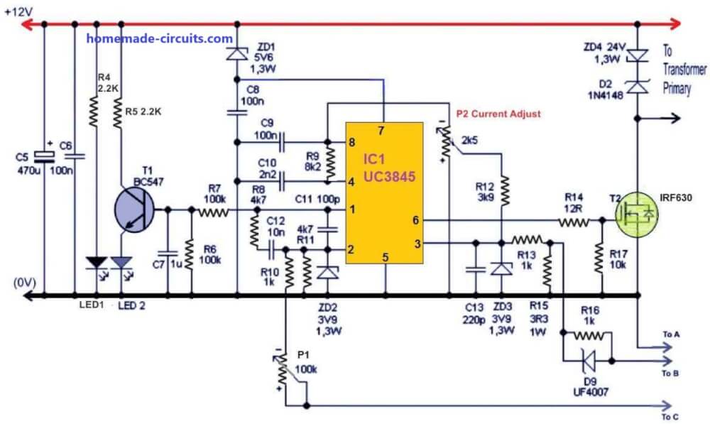
Using IC UC3845 as the Main Controller
The switching supply is powered with IGBT transmitters and is further controlled by UC3845 circuit.
The mains voltage goes straight through the EMC filter which is further checked and filtered on C4 capacitor.
As the capacity is high (50 amps), the inflow in the limiting circuit with Re1 switch and also on R2.
The relay coil and fan, taken from AT or ATX power supply is powered from 12V.
The power is obtained via the resistor from 17V auxiliary supply.
It is ideal to select R1 so that the voltage at the fan and the relay coil limits to 12V.
The auxiliary supply on the other hand uses TNY267 circuit and R27 facilitates protection from under-voltage of auxiliary power.
The power will not turn on if the current is less than 230V. The UC3845 control circuit results to 47% duty cycle (Max.) with the output frequency of 50 kHz.
The circuit is further powered with the help of the zener diode, which actually helps to reduce the supply voltage and even helps to shift the UVLO threshold of lower 7.9V and upper 8.5V to 13.5V and 14.1V respectively.
The source initiates the power and starts working on 14.1V. It never goes below 13.5V and further helps to protect IGBT from desaturation.
However, the original threshold of UC3845 should to set as low as possible.
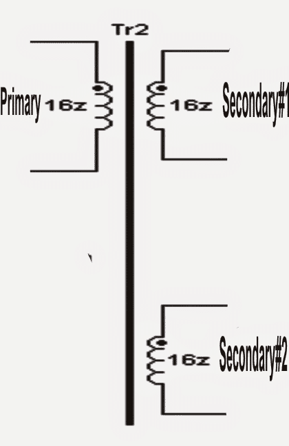
The MOSFET T2 circuit controls, which helps to make Tr2 transformer work offers floating drive and galvanic isolation for the upper IGBT.
It is through the forming circuits of T3 and T4 that it helps to drive T5 and T6 of IGBT and the switch further rectifies line voltage to Tr1 power transformer.
As the output is rectified and reaches an average, it is smoothed by L1 coil and C17 capacitors. The voltage feedback is further connected from output to the pin 2 and IO1.
Furthermore, you can also set the output voltage of power supply with P1 potentiometer. There is no need for galvanic isolation of feedback.
It is because the control circuit of this adjustable SMPS is connected with the secondary SMPS and leaves no connection with the network.
The current feedback is passed through the current transformer TR3 right onto 3 pin IO1 and the overcurrent protection threshold can be set using P2.
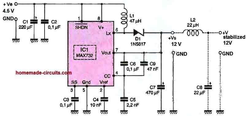
12V input supply may be acquired from an ATX power supply
The Controller Stage Schematic
The IGBT Switching Stage
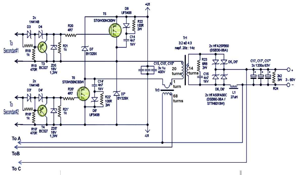
+U1 and -U1 may be derived from mains 220V input after appropriate rectification and filtration
Using Heatsink for the Semiconductors
Also, please remember to place diodes D5, D5 ', D6, D6', D7, D7 ', transistors T5 and T6 on heat sink along with the bridge.
Care should be taken to place snubbers R22 + D8 + C14, capacitors C15 and diodes D7 close to IGBT. The LED1 signals the operation of the supply and LED2 signals the error or the current mode.
The LED glows when the supply has ceased to work in voltage mode. When in voltage mode, the IO1 pin 1 is set to 2.5V else it usually has6V. LED light is an option and you may exclude the same during making.
How to Make the Inductor Transformer
Inductance: For power transformer TR1, the transformation ratio is around 3:2 and 4:3 in primary and secondary. There is also air gap in the ferrite core which is EE shaped.
If you are looking for to wind all by yourself, use a core as it is in an inverter which should size around 6.4 cm2.
The primary is of 20 turns with 20 wires with each having diameter measuring 0.5mm to 0.6mm. The secondary 14 turns with 28 diameters is also of the same measurement like that of primary. Moreover, it is also possible to create windings of copper strips.
It is important to note that application of single thick wire is not a possible idea because of the skin effect.
Now since the winding is not required, you may wind the primary one first followed by secondary. Tr2 forward gate driver transformer possesses three windings having 16 turns each.
It is by using three twisted insulated bell wires that all windings has to be wounded at once leaving any air gap at the wound of the ferrite core.
Next, taking the main power supply from AT or ATX power supply unit of a computer with the core section of around 80 to 120mm2.
The current Tr3 transformer is of 1 to 68 turn on ferrite ring and the number of turns or size is not critical here.
However, the process to orient the winding of transformers must be followed. Also you need to use double choke EMI filter.
The output coil L1 has two parallel inductors of 54uH on iron powder rings. The total inductance is finally 27uH and the coils are wounded by two magnetic copper wires of 1.7mm in diameter, which makes the total L1 cross section to approx. 9 mm2.
The output coil L1 is attached to a negative branch which results no RF voltage in the cathode of diode. This facilitates mounting the same in heat sink without any insulation.
Selecting the IGBT Specs
The max input power of the switched power supply is around 2600W and the resultant efficiency is above 90%.
In switching power supply, you can use STGW30NC60W IGBT type or you can also use other variants like STGW30NC60WD, IRG4PC50U, IRG4PC50W or IRG4PC40W.
You can also use a fast output diode having adequate current rating.
In the worst case scenario, the upper diode gets an average current of 20A while the lower diode in similar situation gets 40A.
Thus it is better to use upper diode half-current than the lower one.
For upper diode, you can use, either HFA50PA60C, STTH6010W or DSEI60-06A else two DSEI30-06A and HFA25PB60.
For lower or bottom diode you can use two HFA50PA60C, STTH6010W or DSEI60-06A else four DSEI30-06A and HFA25PB60.
It is important that the diode of the heat sink must lose 60W (approx.) and loss in IGBT may account to 50W.
However, it is quite hard to ascertain the loss of D7 since it is dependent on Tr1 property.
Moreover, the bridge loss may account to 25W. The S1 switch enables shutdown in standby mode primarily because of the frequent mains switching may not be proper, specifically when using it for laboratory.
In the standby state, the consumption is around 1W and S1 can be skipped.
If you are looking to construct a fixed voltage source of supply, it is also feasible but for the same it is better to apply transformer ratio of Tr1 for maximum efficiency, for instance, in the primary use 20 turns and in secondary use 1 turn for 3.5V – 4V.


Questions & Answers
I want to know that, is this circuit able to charge a 180 Ah tubular inverter battery?
Can I charge this battery using smps of home computer and one more thing , can a battery be charging while using or discharging?
the above circuit will be able to charge a 180AH,
if your computer smps is able to provide upto 20 amps then you can use it to charge the mentioned battery.
No, it's not recommended to use (discharge) the battery while it's being charged.
This site is awsome! I have some doubts about this project: 1) T1 is a power transformer, right? Can I use one of those power transformers from an ATX power supply? 2) T2 has a toroidal core or am I wrong? 3)T3 has a toroidal core too? What's the cross section size? Thank you!
Thanks!!
1) T1 is a power transformer, and an ATX transformer can be used for this provided the winding specs are exactly identical.
2) TR2 should be wound over any standard EE core assembly, not torroidal type core.
3) T3 could be wound over a T13 torroidal core
Hi! im new in electronics and im interested in building a power supply. as i searched i found some types of half bridge drive power supply. what i cant understand in this type is why there is the need of the two mosfets on the high and low side as i cant see any polarity change in the primary. could you please explain the cycle of working in this circuit? are the two mosfets turned on at the same time or not? and if they are whats the need of the high side one? Thanks and sorry for the too many questions..!
Hi, the two mosfets are configured to conduct together simultaneously…..so that the both the fets become in series for conducting the mains 330V…the series connection could be probably to allow sharing of the relatively higher voltage and enable a safer operation of the high current output stage
Hi! Swagatam, I appreciate you for all you have been doing here. I have a design challenge and I am hoping that you would assist me. I am currently building a 48V charger for 16 units of 12V 40AH connected in series and parallel. I need a smart circuit to handle the "Bulk State (constant current), the Topping Stage (constant voltage where the charging current is lowered) and the Floating stage (to compensate for self discharge). I have winded the transformer for it, it has 55V output. I need a circuit to continue from where I stopped.
Thank you in anticipation.
Hi Elias, you can try the following concept:
https://www.homemade-circuits.com/2014/03/fast-battery-charger-circuit.html
just make sure the IC gets a 12V stepped down supply from an emitter follower transistor arrangement, or through any other suitable option
however charging batteries in series parallel is never recommended unless an automatic arrangement is included which would take care of each battery individually
Thanks Swagatam for the prompt reply,you're the man. I have studied the circuit carefully, however, I need a few clarification. Fristly, My transformer is 55V rated, meant to charge 48V battery bank. My concern is how the circuit would detect the change (rise) in battery voltage during charging.
Secondly, what are the modifications needed to effect in order to make the circuit work for the intended use. for example, is there need to change the Zener since it is 6V?
Thirdly, my relays have to be rated at 48V. The relay will be energized by the switching signal from the LM324 but the IC is rated at 32V max. That's way too much voltage for the IC to handle. Even the transistors are not spared.
Elias, I would recommend charging each battery through individual modules, where each module would have the above mentioned fast charger circuitry. This can be a little costlier but will produce extremely reliable results.
Because 48V is not a standard value and components rated with this value are not easily available.
For 48V operation you may have to dimension the components around the opamp in the manner shown for these designs:
https://www.homemade-circuits.com/2012/08/make-this-48v-automatic-battery-charger.html
These adjustments proportionately scale down the 48V into the lower levels for the opamp so that the detection range comes within the safe range of the opamp
however there would be no way to learn the state of each of the batteries separately giving rise to inefficient charging of the 16 batteries.
Thanks a bunch but Sir, I don't quite understand what you mean by "charging each battery through individual modules, where each module would have the above mentioned fast charger circuitry".
Also, I observed that the circuit in the link you provided is not a multi stage. It is just charge and disconnect when battery is full and then engage charging again when the battery drops below the preset voltage.
Is it possible to make it multi stage?
Thanks once again Sir Swagatam.
Please let me know if there's a way one can make a voluntary contribution to homemade-circuit.
Regards.
It's my pleasure Elias, the second link is not a step charger, it was referred only to show you how the opamp and its associated parts needs to be safeguarded from the high 48V, the earlier link which used 4 opamps is what we need to use for implementing the 3 step charging.
I suggest you to make the following circuit module for each of the batteries, and connect the circuits such that the they are placed in between the supply and the respective batteries.
https://www.homemade-circuits.com/2014/03/fast-battery-charger-circuit.html
however this also means that each of the modules will need separate 14.4V for the intended procedures.
So it would be up to you to decide which option you prefer…the 48V one or by using individual circuits for each of the batteries.
Thank you very much for being courteous, I appreciate your thoughts and your involvement with this site, I do not expect any further contributions other than this:)
You can feel free you ask as many questions as you may want.
Hello, First off, Thanks for the assume web-side.
If I want to make a fixed output voltage of 40V. should I use 40V ZD instead of P1? and change the Tr1 secondary winding?
Thanks
thanks, first make the circuit as shown, if you succeed only then you can proceed with the proposed idea
Whats the resistance on the transformer coils thanks
you man inductance? sorry that is not known to me.
Thanks Sourav, I'll investigate the option and if possible try to upadte the design with this feature.
Hi,
I want 12v to 15,20, 25…..48V.
Can I only make circuit using UC3845 and omit second part using transformer?
Can only the first part using UC3845 FULFILL my requirement?
You can also suggest me other less complicated circuit to convert 12v to 15,20, 25…..48V.
Thanks
Hi, you can try the following design instead
https://www.homemade-circuits.com/2014/06/smps-2-x-50v-350w-circuit-for-audio.html
pak ada pcbnya tidak
The power will not turn on if the current is less than 230V.???what u mean..current measured in mA or A (ampere ..milli ampere)rating. but u noted V its voltage
hi,
i'm trying to do such smps in more simpler way <1kw, can i connect the output of uc3844 directly to GDT transformer? i think it's 1A so at 1:1:1 ratio i shall get about 400ma for each mosfet gate, is that good under 1kw output?, also is the protection with 3.9 zeners a must? can't we relay on resistors voltage deviding? also i did modded the driver for more simplicity but how can i post images here for review?
thanks
Hi, the output configuration will need to be a push pull type or an H-bridge type…by using a single mosfet you might not achieve an efficient response from the output which might lack power.
I won't be able to provide a in-depth analysis of the IC since I have not tested the IC practically….
Hi Swagatam Majumdar,,,,
i overviewed your project (Adjustable 0-100V 50 Amp SMPS Circuit)
i am a engineering student and high current smps is my Final year Project , 50 Amp with regulated voltage.
i want to ask where i have to start??? i want a right and exact path
Hello Sohail,
You can start by first buying the parts, then assemble them on a general purpose PCB….if everything works correctly, then design an appropriate PCB for it and then finalize the design by assembling it on the PCB.
hi,is it possible for you to give some info regarding the main power requirement for this project,i.e, common mode choke size/rectifiers/electrolytics capacitance/inrush curent limiter as you do not mention enything on this point!
thank you for your time…
Hi, No I won't be able to provide all those details because I have not yet built and experimented with this design practically…
the article was submitted by another author, not me…
Hi Swagatam,
I know this SMPS design is from another author but in your opinion, will it be possible to leave out TR1 altogether and re-size C17 for the higher output voltage?
Hi Kevin, no I don’t think that’s possible because TR1 is the heart of the whole design and is responsible for generating the required high power output
Hi
Do you have any recommendations for a similar smps (0-100v 30A) without any transformer? I’m looking to build a bench transformerless power supply with wide ranging capability?
without a transformer it will be impossible to step down the input 220V to 100V, so I don’t think that’s feasible without a trafo
Hi
Swagatam! Really appriciate your work in electronics.
I need a circuit which can charge single battery of 48V with 50 Amp. Should i need Constant current source for this?
Can you recomand any such circuit please.
Thanks in Advance
Joshi
Thank you Joshi, yes it has to be a current controlled battery charger which simply means that the source should be rated at the specified amount of current, if a transformer is used then its rating just needs to be as per the battery limitation.
for a 48V, 50AH battery you will require a 48V/6 amp transformer, after rectification its output should reach at around 56V which is the right level for charging a 48V battery.
you can try the first design from the following article:
https://www.homemade-circuits.com/2012/08/make-this-48v-automatic-battery-charger.html
it is designed to automatically cut off when the battery reaches 56V (full charge level)
Which software can i use to simulate this circuit?
Dear Sir,
I need a circuit 0-100Vdc (1 Volt steps programable) by PC or arduino ….
Could you help me ?
Turgay, sorry, I do not have an Arduino design at the moment!
Hai tuan swagatam!saya tertarik dengan proyek ini.apakah ini bisa buat welding juga?terimakasih
Hai Ismail, ya Anda bisa menerapkan sirkuit untuk pengelasan juga!
Hi , sir..
Is the basis of this scheme , Danyk’s scheme ??
Hi Dennis, I have no idea, as it was contributed by another person.
Dear Sir,
the schematic that you share is very interesting, especially the power capable of up to 30 Amperes and the voltage can be set to 100 volts. availability of ferrite transformers that cannot be obtained. For power capable of up to 5KW what size is the fair rite transformer on the market. actually I need a 30 Ampere smps continue with a voltage of 160 Volts, used for AM Transmitters.
maybe you have the SMPS reference and schematic that I need. can the schematic above be developed, just change the coil ratio TR1 and replace the power mosfet
Thank you for your help.
Best regards,
Widiatmono
Thank you Hersan,
Frankly I am not an expert with SMPS transformers, however I have recently published a tutorial on SMPS transformer calculation which might help you to get some insights. Here’s the link for it:
https://www.homemade-circuits.com/how-to-design-and-calculate-ferrite-core-transformers-for-inverters/
hi, can you help me 1 complete circuit diagram?
My input voltage is 100-150VDC (my solar system consists of 3 plates, each plate voltage varies between 38-50VDC)
I want the desired output voltage to be 15VDC (if possible, the better)
Very grateful.
Hi, what is the current required for the 15V, and for what purpose? You can actually get it from one of the panels through a LM317HV voltage regulator
hi dear sir i preferably need a power supply circuit for handling a car’s cooling fan by one SMPS circuit with voltage 14 v and a magnitude current as big as 15 current
please introduce an circuit related
best regards sincerely yours sedigh hosein
Hi Sedigh, sorry I don’t have this circuit, but it may be easily available ready made at less than $20
Hi, I would like to make this 0-100 Volt 0-50 A. power supply. Did anyone do it? It works ?
Can you give me some advice on the realization? For the meantime I made the regulation card with UC3845 up to the gate transformer. I see with the oscilloscope the two commands of the 50 Khz Duty Cycle square wave gate at 48%.
Now I have to think about the IGBT with its snubber and then the transformer, I do it I already have the two semi nuclei to E.
But is it protected against short circuit? With Any output voltage?
Thanks Giovanni Verona Italy
Hi, It is a tested design by some other author, but since it was not designed me providing all the minute details will be difficult for me, I am sorry about that!