Today I will explain to you how this simplest constant voltage and constant current battery charger circuit works. This circuit is very nice for charging battery safely without damaging it. It has two main jobs, one is limiting high current and second is stopping over voltage.
Audio/Video Representation
Main Parts Used In Circuit
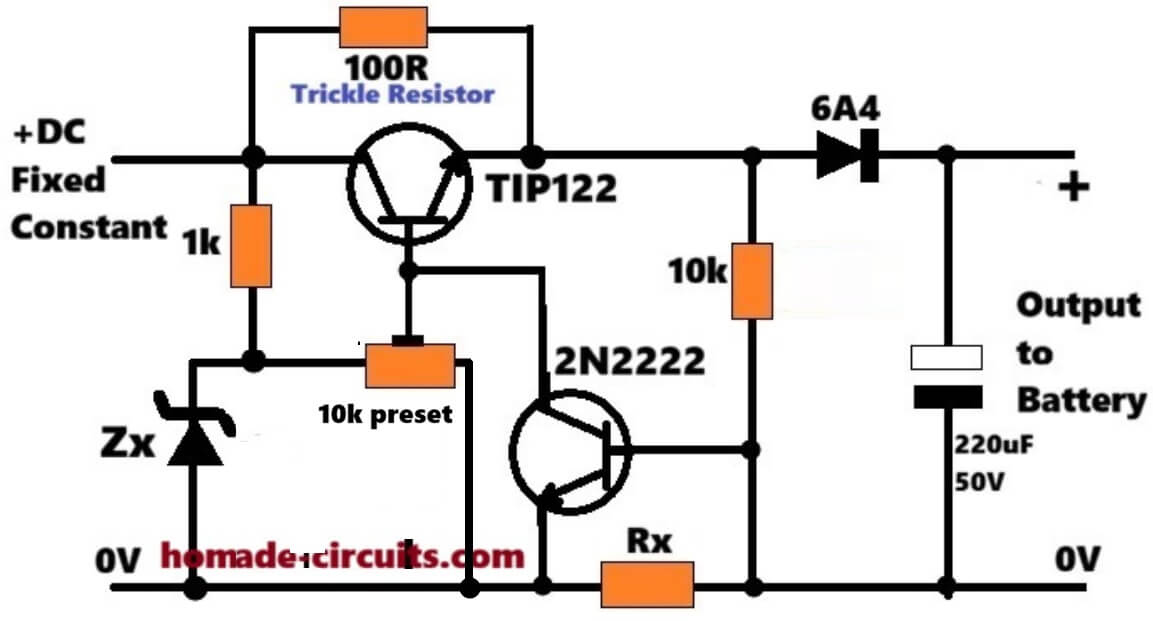
In this circuit we are using TIP122 NPN Darlington transistor as main pass element. For current sensing and limiting we are using 2N2222 transistor. For fixing maximum voltage we have Zener diode Zx and one 10k preset potentiometer.
Then we have Rx resistor for sensing current flow. There is one 100 ohm resistor given for trickle charging. One 6A4 diode is put at output side so battery current cannot flow backward into circuit when input supply is off.
Finally one 220 uF 50 volt capacitor is given for filtering.
How Constant Voltage (CV) Working
First current comes from positive DC input and goes into base of TIP122 through 1k resistor so transistor turns on.
Zener diode Zx creates fixed voltage reference point. With 10k preset potentiometer you can easily rotate and adjust exact output voltage like 13.8 volt or 14.4 volt according to your 12 volt battery requirement.
When output voltage reaches this set limit the base drive gets controlled so voltage will not increase further.
How Constant Current (CC) Working
All returning current from battery goes to ground through Rx resistor. Voltage drop happens across Rx resistor according to Ohm law. This voltage drop is directly connected to base and emitter of 2N2222 transistor.
When charging current becomes too high then voltage drop across Rx reaches around 0.65 volt. At this moment 2N2222 transistor turns on automatically. Once 2N2222 turns on it pulls down base of TIP122 transistor towards ground.
Because of this TIP122 gets less base current and limits total charging current.
Maximum current limit formula is simple Rx = 0.65 / Max current.
Trickle Charging And Full Charge Condition
When battery becomes fully charged its voltage rises up and charging current automatically reduces down. Because current becomes less the voltage across Rx drops below 0.65 volt so 2N2222 turns off completely.
Now circuit stays at set constant voltage. Even if TIP122 stops heavy conduction the 100 ohm trickle resistor keeps sending very small tiny current to battery so battery remains fully charged continuously without any overcharging problem.
Upgrading to High Current, CC, CV Battery Charger Version
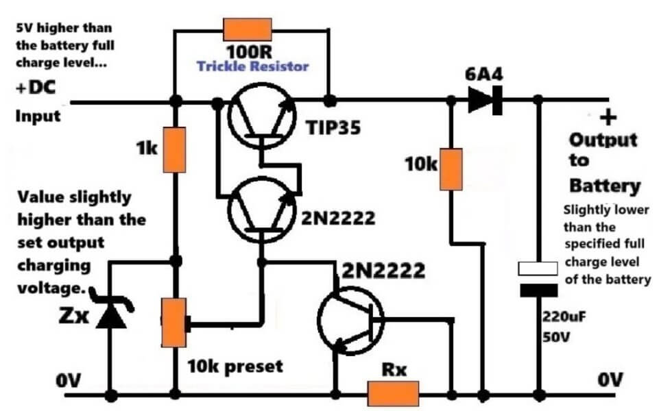
The above explained simplest CC, CV battery charger with trickle charging can be upgraded to a high current version, up to 10 amps, simply by replacing the TIP122 with a Darlington pair, using TIP35 and 2N2222, as shown below...


Questions & Answers
Hello swagatam. Have a nice day. I would like you to help me with a circuit to sense the voltage level of 2v 55Ah lithium batteries when it drops to notify the electric generator to operate to charge the batteries.
sorry for the typo. the batteris are 500 Ah not 55. is the circuit still feasible in this case?
Yes, you can still use the BJJT circuit, as given below, just replace the 33k with 10k and 47k preset with 10k preset.:
https://www.homemade-circuits.com/wp-content/uploads/2020/02/low2Bbattery2Bindicator2Bcircuit.jpg
However, you cannot use the relay, because relay cannot operate with 2V supply…
Hi Abu,
I think you can try one of the circuits explained in the following article, and let me know if you face any issues:
https://www.homemade-circuits.com/low-battery-indicator-circuit-using-two/
what sort of value of zenner diode is required.
zener diode provides the maximum safe range for the output voltage.
For example for a 12V battery this zener diode could be selected such that the maximum output even without the preset resistor is around 14.3V. Once this is fixed, the preset can be used to fine tune this voltage further to 14V.