Special thanks to Mr. Ike Higgins for emailing me this article exploring a theoretical concept known as the Bubble Current Machine. Please note that this is presented purely as a conceptual thought experiment and design proposal. In practical physics, pushing air through a submerged nozzle against hydrostatic pressure requires external work equal to (or greater than) the buoyant energy generated. We encourage our readers to analyze the fluid mechanics, test the membrane dynamics, and join the discussion in the comments!
Introduction to Harvesting Energy from Nature
In a quest to find new ideas and ways to harvest energy without creating problems and destruction to the biosphere, experience shows the best resource to harvest from is Nature.
Nature provides countless behaviors and characteristics that present opportunities for us to harvest.
Most of the ones we have currently implemented boil down to mass in motion. We know how to build machines that take advantage of mass in motion to operate for our benefit.
Wind mills are one. We build a structure, then place it in front of Nature caused mass in motion. The wind blows. The earth rotates (reference “Earth Torque Generator”). Rivers flow due to gravity. Mass in motion. Look what we can do with that.
The point is that Nature causes mass to move. How else can we harvest from that?
Bubble current results from a natural harvest from gravity that I will now describe as a conceptual chain of physics, that moves mass. Engineers can go from there. This is just another way to harvest energy from gravity.
The Physics of Gravity, Mass, and Volume
Gravity shows up on mass as a one-way force vector, pointing down (using the earth for this discussion).
For a given quantity of mass, the force is equal for wherever the mass is resident. Meaning, if in the same local environment, the same quantity of mass in lead compared to the same quantity of mass in water results in the same gravitational force.
There is a big difference in the cubic volume of those two examples, but mass weighs the same in the same gravitational field. This is very evident with respect to states of mass. Solid, liquid, gas, etc.
One of the characteristics for the state of mass is cubic volume. A molecule of water is smaller than a molecule of ice. Therefore, if comparing by cubic volume, a specific volume of water weighs more than the same cubic volume of ice.
Since the ice “weighs less” than the water, ice floats. Gravity causes the layering of mass, per cubic volume.
Pressure Equalization and Bubble Current
There are other parameters that are involved with making ice float. For instance, the propagation of energy (pressure equalization) is different between liquid and gas environments.
Both water and air are made of mass in different states. When in contact, there is pressure equalization (energy sharing) between the two.
However, by cubic volume, gravity is exerted on water with more pressure than on the same cubic volume of gas. Bubbles float to the top. This is Nature moving mass.
Gravity provides the environment where the layering of mass in a cubic volume happens. The reality is that the mass of the air bubble is lifted by the gravitational environment that is ambient to the mass structure.
Gravity in, mass in motion out. But the direction of motion of this mass is up, not down. Bubble current.
Conceptual Architecture of the Sealed Container
Humans can now design an architecture to create the environment where nature (gravity) does its thing consistently. The sun, wind, or rain is not a consistent input.
The architecture needed for consistent bubble current can be described with the following conceptual functionality. Below is a diagram of a conceptual function, not the detailed design to implement that function.
Actually, there is some pretty deep physics involved in the actual design effort. I won’t go that deep herein.
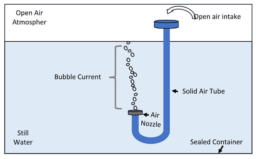
The diagram shows a sealed container, three quarters full of water, with normal atmosphere above the water. The temperature is constant. It is sealed so there is a constant cubic volume, a constant number of water molecules, and a constant number of air particles (molecules, ions, etc.).
It is all stable (standing still). Being a sealed container is an important point with respect to the physical phenomena described below.
Air Tube and Hydrophobic Nozzle Mechanics
Mounted in the container is a solid tube, in this concept in the shape of a “J”. That “air tube” is solid and the pressure of the water does not affect the open-air space inside the tube.
The top of the tube is open to the free air atmosphere at the top of the container. The other end of the tube, under water, has a “nozzle” where air can escape, but water cannot pass backwards in to the air tube. This is accomplished using currently known technology.
To be bluntly brief, the technology for the nozzle structure includes the use of Hydrophobic Membranes of PTFE polymers, or breathable membrane vents, or other known tech options.
But a Hydrophobic Microporous Membrane with the proper LEP (liquid entry pressure) higher than the water pressure at the membrane will result in the nozzle functionality of air passing through but water being kept out. (The design implementation is a bit complex and detailed but currently doable.)
Air Circulation and Gravity Input
Since the Air Tube is solid, the atmosphere within the tube extends from above the surface of the water to the nozzle end under the water. The natural environment for bubble current is established.
The air in the tube, nozzle end, will pass thru the membrane and…bubbles up. The bubbles will transit the water and reenter the free air.
When those bubbles leave the nozzle, more air from the atmosphere will move through the air tube to replace them. There will be an air circulation from the atmosphere, down the tube, up through the nozzle.
The atmosphere will then be replenished by bubbles escaping from the top of the water. Due to the sealed container, the atmosphere remains, relatively speaking for this discussion, stable.
With a stable air circulation creating a stable bubble current. Gravity in, mass in constant motion out. Due to the architecture and technology that we built and placed in front of Nature.
Addressing Perpetual Motion Concerns
This would be the point where some would be declaring “perpetual motion machine” and the impossibility of that becoming real.
Although this would continuously work until something breaks or just wears out, it is not perpetual motion. The reason is that it is being continually fed, the input to the manmade machine, by the ambient ubiquitous gravity.
It is my understanding that perpetual motion machines do not require an input of energy to operate. I may not be exactly technically correct in detail here, but I don’t think this is perpetual motion.
Mechanical Harnessing of Buoyancy
Now we have mass in constant motion. Bubble Current. What can we do with it? And how? Following is a conceptual use of this natural mass in motion.
This particular mass in motion concept is already being used by us. In under water salvage they use balloons to lift specimens to the surface. Fill the balloon attached to something, and if enough air is in the balloon the “lift” capability does the job.
That lift capability is called buoyancy. The buoyancy determines the limit of the load to be lifted. That buoyancy comes from the differential in gravitational force environments, liquid and gas, due to the cubic volume characteristics described above. That is the concept for the Bubble Current Machine.
Mechanical Setup and Practical Applications
The diagram below demonstrated how the individual bubbles from the nozzle can be captured to create a single bubble with buoyancy. The bubbles are gathered in the Lift Bowls.
Depending on the detailed design, each Lift Bowl has a specific lift capability. If mechanically connected, several Lift Bowls provide lift at the same time. The total lift force is then used to turn a gear. We all know what we can do with a turning gear.
This is the architecture that is presented in the diagram below.
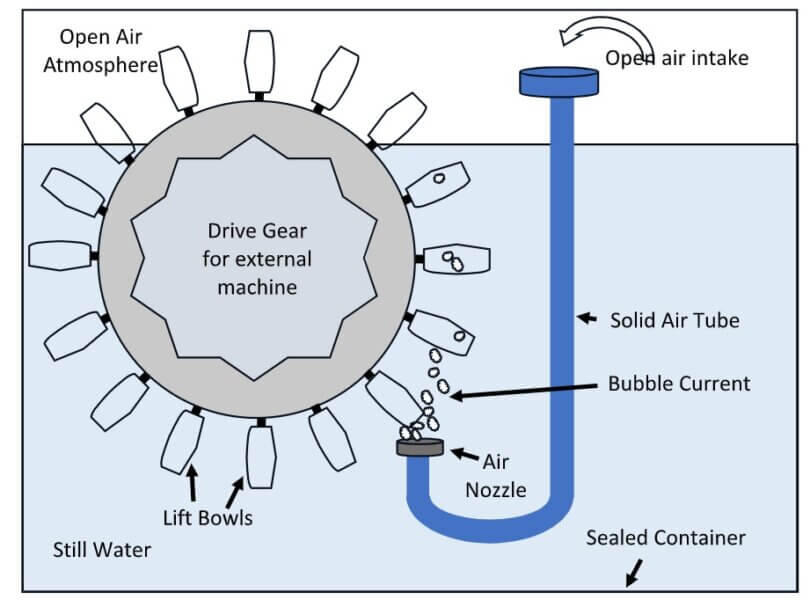
A mechanical structure is designed such that a Ferris Wheel type of set up is achieved.
Lift Bowls are attached to the wheel (gear) with specific orientation so they catch the bubble current on one side. When they reach the top in the open atmosphere, the tilting of the Lift Bowls allows the air to escape and then the bowls to fill with water for their trip down the other side.
The rotation of the wheel applies a torque force to the spinning gear commiserate with the total buoyancy of the Lift Bowls. That torque force can be used, through mechanical engineering technics, to operate an external machine.
One of my first thoughts, with the home aquarium size Bubble Current Machine described here, is to have the external mechanics pick up and lift a marble from the surface and elevate it to the top of a Rube Goldberg machine. Drop the marble and the RG machine does its elaborate operations until the marble reaches the bottom.
The Bubble Current Machine then lifts the marble again and it starts all over. A continuously operating Rube Goldburg machine. That would make parents very happy. Don’t you think.
The point here is that gravity can be harvest in many ways. Reference “The Higgins Engine” as another way. The architecture and natural physics of the Bubble Current Machine provides for the harvest of energy from gravity.
No other inputs required. This provides one more line item on the list of harvestable energy from Nature that may be used by humans. We need the ideas. Anybody got any other ideas?
Physics Addendum
So much for the common language presentation. I now realize that description provided some ambiguity due to lack of detail. I will now provide some actual physics and engineering design considerations that, I hope, will at least significantly reduce that confusion and ambiguity.
First some clarifications. For this we will just forget about the “external mechanics”, the Rube Goldberg machine, that I attached to the Bubble Current Machine. Although there are ways to attach such a thing without violating the “sealed” container. Just the fact that the Ferris Wheel is turning inside the sealed container is sufficient proof of concept.
All references to “free air” or “free atmosphere” refer only to the volume of air within the sealed container. Not the atmosphere external to the container. It is the same clarification for references to the “water or liquid environment”. Only the volume and cubic space of the water within the sealed container is considered.
My use of “continuous” was not meant to mean the machine would operate forever. There are many physical properties that prevent that from happening. We would classify those as just wearing out (although the actual physics of wearing out is a list of things like friction and static pressure and other specifics).
But the important physics is that the sealed container contains all the energy that will ever be in that container. Gravity does not input energy. Gravity produces the environment where the physical phenomena can manifest. It is that physical phenomena that makes the wheel turn, using the energy within the sealed container. It is the continuous flow of gravity through the machine that was meant to be the reference. The “environment” is continuously replenished.
Because of the different environments (gas and liquid), and the sealed container, the energy within the tank will, due to the laws of nature, steadily progress towards total equilibrium. That is a state where the pressures within and across the environments reach a point where there is no energy movement. Everybody is calm. Think of energy always being there, but in a state of excitation. When all the energy is “relaxed”, the system is in equilibrium. There is still a difference in pressure between the air and water, but no energy transfer between the two is happening.
When the energy is “excited”, then pressure equalization happens, in accordance with the physics of the gas and liquid environments. As any excitation happens, the process of achieving equilibrium then proceeds. Thanks to gravity and the natural behaviors within the medium where the energy resides. This is the physics that the Bubble Current Machine takes advantage of. The excitation (including relocation and pressure differentials) of energy already in there, and the resulting equalization process from that excitation.
Now, more detail about the nozzle. The engineering design of the membrane is all important. The design requirements for a membrane include parameters representing the flow rate of the air through the membrane. There are options over a range of desired capabilities. The options include a range from fast to slow flow through the membrane. The point here is that the membrane is designed to always “leak”, as long as the water pressure does not exceed the Liquid Entry Pressure (LEP) of the membrane.
Using the aquarium size of the example, the pressures involved allow for “continuous” leakage. Of course, that does not mean forever due to “wear out”. And the design for implementation of the membrane has to be such that many issues are addressed. All involve water finding its way in to or around the membrane and/or the air tube. But this technology is known to us and design of the specific architecture for specific use are addressed by a sealing geometry. But it is human made. Nothing human made is 100%.
In addition to this desired leakage, any advantageous change in the pressure differentials between the top (water) and bottom(air) of the membrane will cause air to be forced though the membrane. The total amount of air flowing through is the addition of the two phenomena, leakage and forced.
Where does this “advantageous” change in the pressures on the membrane come from? The start up configuration of the sealed container provides the means. To set this start up configuration requires that the Ferris Wheel be locked in place, and membrane end of the air tube (full of air) is closed. Then each of the Lift Bowls on the lifting side of the Ferris Wheel are filled with air. The wheel cannot turn. It is locked. At this point, the container is then sealed.
This start up architecture establishes the cubic volume of the water and air in the sealed tank. The volume of the liquid environment includes all the water, the solid volume of the lift bowls in the water, and the cubic volume of the air in the Lift Bowls at that water pressure. Which has a differential between the surface and the depth of the water.
The cubic volume of the captured atmosphere includes all the free air above the surface of the water and in the air tube, as well as the cubic volume of the solid Lift Bowls in the atmosphere. The “number of air particles” in that atmosphere creates the air pressure (along with temperature and humidity). The air pressure, due to gravity, has a differential between the top of the atmosphere and the bottom of the air tube. At system equilibrium these two cubic volumes (air and water) are stable.
Start up is when, at the same time, the Ferris Wheel is unlocked and the end of the air tube is opened up. Air leakage through the membrane begins, at the rate designed for the membrane. This means a time frame per volume of air entering the water. The leaked air, bubbles, inject new cubic volume to the water environment and reduces the pressure in the air environment. But the cubic volume of the air bubbles is less than if that same air resides in the atmosphere. The air pressure versus the water pressure.
When the first Lift Bowl reaches the water surface, it releases the “water pressure compressed” air bubble to the atmosphere. Very quickly. The difference between pressure equalization operation in air versus water. That air bubble then disperses in the atmosphere by expansion and pressure equalization in a gas environment. There are now more air particles in the atmosphere than there were before the Lift Bowl emptied.
Resulting in a short quick rise in air pressure. Also, the total volume of the water environment reduces by the cubic volume of the “compressed” air that was released. The surface level of the water has to drop that amount. You can think of it as a punch to the system. After that punch, pressure equalization begins.
The air in the air tube experiences the punch as part of the atmosphere. Which means the air pressure at the membrane increases. Which means there is a forced amount of air through the membrane. Then everybody goes to the equalization process until equilibrium. But then the next Lift Bowl reaches the top and resets the sequence before equilibrium can manifest.
The system does not immediately equilibrate because the wheel rotation and the pulsed “reset” from successive bowl releases keep introducing a non-zero pressure/volume differential, so the transients repeat for a long time. It is a relaxation/oscillation phenomenon. Repeated pulsing can prolong the time until full equilibrium because the system is being nudged away for equilibrium at discrete moments. The synchronization/differential-reset concept allows the system to produce a longer-lasting sequence of transients.
The process will die out because the stored energy available from the initial pressure/volume imbalances is finite and dissipates with the work (friction) of the wheel and other issues such as humidity (as the bubbles rise through the water, they collect vapor which changes the resulting pressure equalization parameters and impacts the membrane operation), etc.
The final result is the validation of the original physics concept for the Bubble Current Machine. Gravity (nature) interacts with the architecture (Bubble Current Machine) we put in front of it, and mass moves in a fashion that we want. We are harvesting from the properties of gravity. A Hydrophobic Microporous Membrane with the proper LEP higher than the water pressure at the membrane in the architecture of the Bubble Current Machine will result in the turning of the Ferris Wheel. Proof of concept.



Questions & Answers
Interesting. However the “Farris-type” wheel passing out of the water into open air violates the “sealed water chamber” that was pointed out as being vital important to the operation of this device.
There is now a “physics addendum” added to the post that should clear up the ambiguity about the “sealed water chamber” and “open air” volumes. The Ferris Wheel is never outside the sealed tank.