In this post I am showing you one very nice and simple solar powered egg incubator circuit project. Many people ask me bro how to upgrade simple incubator with solar charger and battery backup so egg will not spoil when main power line is going off.
In rural areas power cut is major problem for egg hatching, so this project will solve your full problem easily with cheap components.
Audio/Video Representation
What is Main Problem in Normal Incubator Circuit?
Normally in simple incubator we use LM35 temperature sensor and LM393 comparator with relay to control light bulb heat. But problem is when grid electricity goes away, lamp turns off, temperature drops down and all eggs inside incubator get ruined.
Also if we connect battery directly without protection, battery will get over discharged and fully damage in few days. So we need two extra things: proper solar charging regulator and battery deep discharge cutoff circuit.
Solar Panel and Charging Section Setup
First component you need is 20 Volt 1 Ampere solar panel. But directly connecting 20V to 12V 7Ah battery is dangerous, it will overcharge and swell battery.
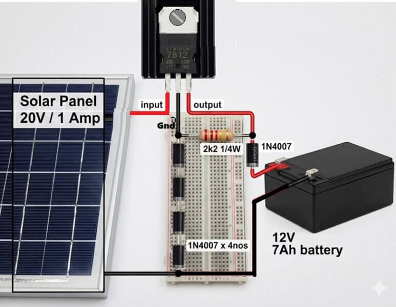
So here we use 78T12 transistor type voltage regulator IC. Normal 7812 gives exact 12V output, but lead acid battery needs around 14.2V to 14.4V for full charging.
To boost voltage output of 78T12, we connect 4 numbers of 1N4007 diodes in series between ground pin of 78T12 regulator and actual ground wire. Each diode gives around 0.6V to 0.7V drop, so 4 diodes will raise ground reference by 2.6V to 2.8V. Now output from 78T12 becomes around 14.6V which is perfect for charging 12V battery.
Also put 2.2k resistor and 1N4007 series diodes at battery input line to prevent reverse current from battery to solar panel during night time.
Low Voltage Deep Discharge Cutoff Protection
This is most important part of circuit to save battery life. If battery voltage goes below 10.5V, circuit must automatically disconnect load.
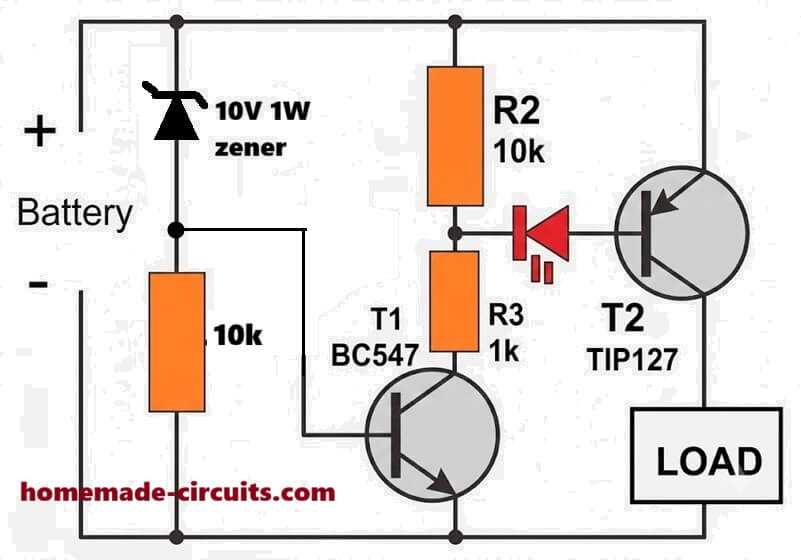
For this section we use 9V Zener diode, one BC547 NPN transistor (T1) and one TIP127 PNP Darlington transistor (T2).
When battery voltage is healthy (above 10V), current passes through 9V Zener diode into base of BC547 transistor T1. Transistor T1 turns ON and pulls down base pin of TIP127 transistor T2.
When base of TIP127 PNP transistor goes LOW, TIP127 turns ON fully and allows positive voltage to pass to incubator thermostat circuit.
When battery drops below 10V, then Zener diode stops conducting. T1 base current becomes zero, so T1 turns OFF.
As T1 turns OFF, base of T2 floats HIGH through 10k resistor, turning OFF TIP127 transistor. Now full incubator thermostat section is completely cut off from battery, so battery is saved from deep discharge death.
Temperature Controller LM35 and LM393 Comparator Section
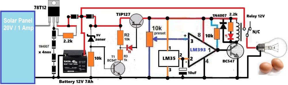
Once power passes through TIP127 transistor, it supplies 12V supply to LM35 sensor and LM393 comparator IC.
LM35 is simple temperature sensor giving 10 millivolts per degree celsius. Output pin 2 of LM35 is connected to inverting input pin 2 of LM393 IC.
We connect 10k preset potentiometer to non inverting input pin 3 of LM393. By adjusting this 10k preset, you can set target hatching temperature like 37.5 degree celsius.
LM393 compares both voltage levels. If incubator inside temperature is lower than set value, LM393 output pin 1 goes HIGH. This HIGH signal turns ON BC547 driver transistor which energizes 12V Relay coil. Relay contacts close and switch ON heating bulb.
When temperature inside incubator reaches set limit, LM393 output pin 1 goes LOW, BC547 turns OFF, relay turns OFF and bulb shuts off automatically.
A flyback diode 1N4007 is connected across relay coil to absorb reverse inductive voltage spikes and protect driver BC547 transistor.
Components List
- Solar Panel 20V 1A
- Voltage Regulator IC 78T12
- Battery 12V 7Ah Lead Acid
- Diodes 1N4007 (7 pieces total)
- Zener Diode 9V
- Transistors BC547 (2 pieces) and TIP127 PNP Darlington (1 piece)
- Resistors 2.2k (2 pieces), 10k (2 pieces), 1k (1 piece)
- Preset Potentiometer 10k
- IC LM393 Comparator and IC LM35 Temperature Sensor
- Capacitor 10uF
- 12V Relay, LED indicator, and 12V Heating Bulb / Load
Conclusion
By adding this simple solar charger with 78T12 plus 4 diodes and deep discharge protection using Zener and TIP127, your egg incubator will run automatically 24 hours without fear of load shedding or battery failure. Build this circuit on general purpose PCB and adjust 10k preset properly using digital thermometer. If you have any doubt please comment below.



Need Help? Please Leave a Comment! We value your input—Kindly keep it relevant to the above topic!