In this post I have explained the construction of a 5000 watt inverter circuit which incorporates a ferrite core transformer and therefore is hugely compact than the conventional iron core counterparts.
Block Diagram
Please note you can convert this ferrite core inverter to any desired wattage, right from 100 watt to 5 kva or as per your own preference.
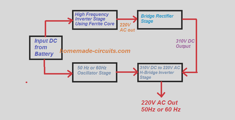
Understanding the above block diagram is quite simple:
The input DC which could be through a 12V, 24V or 48V battery or solar panel is applied to a ferrite based inverter, which converts it into a high frequency 220V AC output, at around 50 kHz.
But since 50 kHz frequency may not be suitable for our home appliances, we need to convert this high frequency AC into the required 50 Hz / 220V, or 120V AC / 60Hz.
This is implemented through an H-bridge inverter stage, which converts this high frequency into output into the desired 220V AC.
However, for this the H-bridge stage would need a peak value of the 220V RMS, which is around 310V DC.
This is achieved using a bridge rectifier stage, which converts the high frequency 220V into 310 V DC.
Finally, this 310 V DC bus voltage is converted back into 220 V 50 Hz using the H-bridge.
We can also see a 50 Hz oscillator stage powered by the same DC source. This oscillator is actually optional and may be required for H-bridge circuits which do not have its own oscillator. For example if we use a transistor based H-bridge then we may need this oscillator stage to operate the High and low side mosfets accordingly.
UPDATE: You may want to jump directly to the new updated "SIMPLIFIED DESIGN", near the bottom of this article, which explains a one-step technique for obtaining a transformerless 5 kva sine wave output instead of going through a complex two-step process as discussed in the concepts below:
A Simple Ferrite Cote Inverter Design
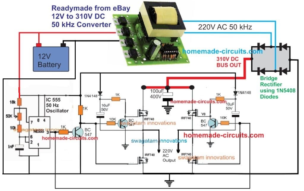
Before I have explained the 5kva version here's a simpler circuit design for the newcomers. This circuit does not employ any specialized driver IC, rather works with only n-channel MOSFETS, and a bootstrapping stage.
The complete circuit diagram can be witnessed below:
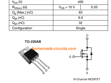
400V, 10 amp MOSFET IRF740 Specifications
In the above simple 12V to 220V AC ferrite inverter circuit we can see a ready made 12V to 310V DC converter module being used. This means you don't have to make a complex ferrite core based transformer. For the new users this design may be very beneficial as they can quickly build this inverter without depending on any complex calculations, and ferrite core selections.
5 kva Design Prerequisites
First you need to find 60V DC power supply for powering the proposed 5kVA inverter circuit. The intention is to design a switching inverter which will convert the DC voltage of 60V to a higher 310V at a lowered current.
The topology followed in this scenario is the push-pull topology which uses transformer on the ratio of 5:18. For voltage regulation which you may need, and the current limit – they are all powered by an input voltage source. Also at the same rate, the inverter expedites the current allowed.
When it comes to an input source of 20A it is possible to get 2 – 5A. However, the peak output voltage of this 5kva inverter is around 310V.
Ferrite Transformer and Mosfet Specifications
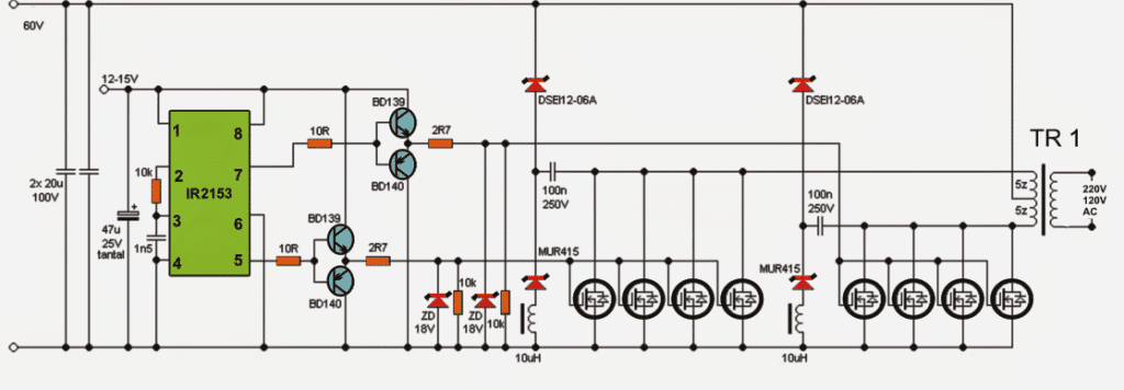
In regard to the architecture, Tr1 transformer has 5+5 primary turns and 18 for secondary. For switching, it is possible to use 4+4 MOSFET (IXFH50N20 type (50A, 200V, 45mR, Cg = 4400pF). You are also free to use MOSFET of any voltage with Uds 200V (150V) along with least conductive resistance. The gate resistance used and its efficiency in speed and capacity must be excellent.
The Tr1 ferrite section is constructed around 15x15 mm ferrite c. The L1 inductor is designed using five iron powder rings that may be wound as wires. For inductor core and other associated parts, you can always get it from old inverters (56v/5V) and within their snubber stages.
Using a Full Bridge IC
For integrated circuit the IC IR2153 can be deployed. The outputs of the ICs could be seen buffered with BJT stages. Moreover, due to the large gate capacitance involved it is important to use the buffers in the form of power amplifier complementary pairs, a couple of of BD139 and BD140 NPN / PNP transistors do the job well.
Alternate IC can be SG3525
You may also try to use other control circuits like SG3525. Also, you can alter the voltage of the input and work in direct connection with the mains for testing purpose.
The topology used in this circuit has the facility of galvanic isolation and operating frequency is around 40 kHz. In case if you have planned to use the inverter for a small operation, you don’t cooling, but for longer operation be sure to add a cooling agent using fans or large heatsinks. Most of the power is lost at the output diodes and the Schottky voltage goes low around 0.5V.
The input 60V could be acquired by putting 5 nos of 12V batteries in series, the Ah rating of each battery must be rated at 100 Ah.
High Frequency 330V Stage
The 220V obtained at the output of TR1 in the above 5 kva inverter circuit still cannot be used for operating normal appliances since the AC content would be oscillating at the input 40 kHz frequency.For converting the above 40 kHz 220V AC into 220V 50 Hz or a 120V 60Hz AC, further stages would be required as stated below:
First the 220V 40kHz will need to be rectified/filtered through a bridge rectifier made up of fast recovery diodes rated at around 25 amps 300V and 10uF/400V capacitors.
Converting 330 V DC into 50 Hz 220 V AC
Next, this rectified voltage which would now mount up to around 310V would need to be pulsed at the required 50 or 60 Hz through another full bridge inverter circuit as shown below:
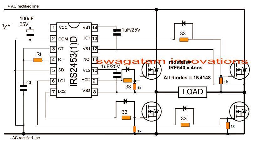
The terminals marked "load" could be now directly used as the final output for operating the desired load.
Here the mosfets could be IRF840 or any equivalent type will do.
How to Wind the Ferrite Transformer TR1
The transformer TR1 is the main device which is responsible for stepping up the voltage to 220V at 5kva, being ferrite cored based it's constructed over a couple of ferrite EE cores as detailed below:
Since the power involved is massive at around 5kvs, the E cores needs to be formidable in size, an E80 type ferrite E-core could be tried.
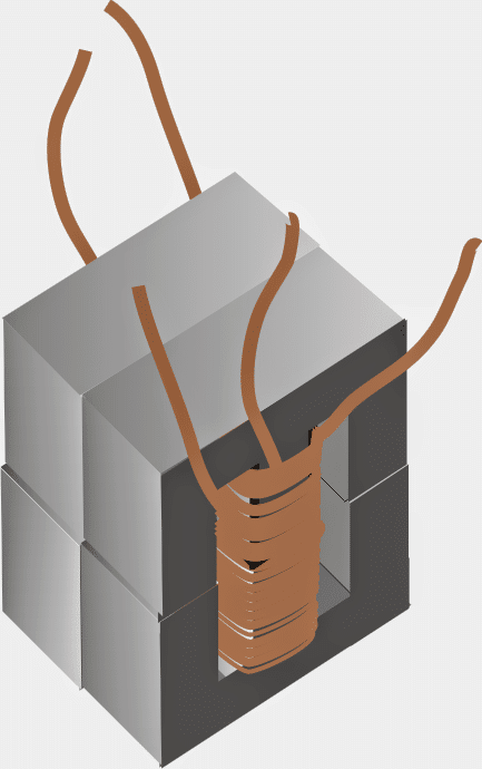
Remember you may have to incorporate more than 1 E core, may be 2 or 3 E-cores together, placed side by side for accomplishing the massive 5KVA power output from the assembly.
Use the largest one that may be available and wind the 5+5 turns using 10 numbers of 20 SWG super enameled copper wire, in parallel.
After 5 turns, stop the primary winding insulate the layer with an insulating tape and begin the secondary 18 turns over this 5 primary turns. Use 5 strands of 25 SWG super enameled copper in parallel for winding the secondary turns.
Once the 18 turns are complete, terminate it across the output leads of the bobbin, insulate with tape and wind the remaining 5 primary turns over it to complete the ferrite cored TR1 construction. Don't forget to join the end of the first 5 turns with the start of the top 5 turn primary winding.
E-Core Assembly Method
The following diagram gives an idea regarding how more than 1 E-core may be used for implementing the above discussed 5 KVA ferrite inverter transformer design:

E80 Ferrite core

Feedback from Mr. Sherwin Baptista
Dear All,
In the above project for the transformer, i did not use any spacers between the core pieces, the circuit worked well with the trafo cool while in operation. I always preferred an EI core.
I always rewound the trafos as per my calculated data and then used them.
All the more the trafo being an EI core, separating the ferrite pieces were rather easy than doing away with an EE core.
I also tried opening EE core trafos but alas; i ended up breaking the core while separating it.
I never could open an EE core without breaking the core.
As per my findings, few things i would say in conclusion:
---Those power supplies with non-gaped core trafos worked best. (i am describing the trafo from an old atx pc power supply since i used those only. The pc power supplies do not fail that easily unless its a blown capacitor or something else.)---
---Those supplies that had trafos with thin spacers often were discolored and failed quiet early.(This i got to know by experience since till date i bought many second hand power supplies just to study them)---
---The much cheaper power supplies with brands like; CC 12v 5a, 12v 3a ACC12v 3a RPQ 12v 5a all
Such types ferrite trafos had thicker paper pieces between the cores and all failed poorly!!!---
In FINAL the EI35 core trafo worked the best(without keeping air gap) in the above project.
5kva ferrite core inverter circuit preparation details:
Step 1:
- Using 5 Sealed Lead Acid batteries of 12v 10Ah
- Total voltage = 60v Actual voltage
- = 66v fullcharge(13.2v each batt)voltage
- = 69v Trickle level charge voltage.
Step 2:
After calculation of battery voltage we have 66volts at 10 amps when full charged.
- Next comes the supply power to ic2153.
- The 2153 has a maximum of 15.6v ZENER clamp betwen Vcc and Gnd.
- So we use the famous LM317 to supply 13v regulated power to the ic.
Step 3:
The lm317 regulator has the following packages;
- LM317LZ --- 1.2-37v 100ma to-92
- LM317T --- 1.2-37v 1.5amp to-218
- LM317AHV --- 1.2-57v 1.5amp to-220
We use the lm317ahv in which 'A' is the suffix code and 'HV' is the high volt package,
since the above regulator ic can support input voltage of upto 60v and output votage of 57 volts.
Step 4:
- We cannot supply the 66v directly to the lm317ahv package sice its input is maximum of 60v.
- So we employ DIODES to drop the battery voltage to a safe voltage to power the regulator.
- We need to drop about 10v safely from the maximum input of the regulator which is 60v.
- Therefore, 60v-10v=50v
- Now the safe maximum input to the regulator from the diodes should be 50 volts.
Step 5:
- We use the regular 1n4007 diode to drop the battery voltage to 50v,
- Since being a silicon diode the voltage drop of each is about 0.7 volts.
- Now we calculate the required number of diodes we need which would buck the battery voltage to 50 volts.
- battery voltage = 66v
- calc.max input voltage to regulator chip = 50v
- So, 66-50=16v
- Now, 0.7 * ? = 16v
- We divide 16 by 0.7 which is 22.8 i.e., 23.
- So we need to incorporate about 23 diodes since the total drop from these amounts to 16.1v
- Now, the calculated safe input voltage to the regulator is 66v - 16.1v which is 49.9v appxm. 50v
Step 6:
- We supply the 50v to the regulator chip and adjust the output to 13v.
- For more protection, we use ferrite beads to cancel out any unwanted noise on the output voltage.
- The regulator should be mounted on an appopriate sized heatsink in order to keep it cool.
- The tantalum capacitor connected to the 2153 is an important capacitor that makes sure ic gets a smooth dc from the regulator.
- Its value can be reduced from 47uf to 1uf 25v safely.
Step 7:
- Rest of the circuit gets 66volts and the high current carrying points in the circuit should be wired with heavy guage wires.
- For the transformer its primary should be 5+5 turns and secondary 20 turns.
- The frequency of the 2153 should be set at 60KHz.
Step 8:
The High frequency ac to low frequency ac converter circuit using the irs2453d chip should be wired appropriately as shown in the diagram.
Finally completed.
Making a PWM Version
The following posting discusses another version of a 5kva PWM sinewave inverter circuit using compact ferrite core transformer. The idea was requested by Mr. Javeed.
Technical Specifications
Dear sir, would you please modify its output with PWM source and facilitate to make use such an inexpensive and economical design to World wide needy people like us? Hope You will consider my request. Thanking you.Your affectionate reader.
The Design
In the earlier post I introduced a ferrite core based 5kva inverter circuit, but since it is a square wave inverter it cannot be used with the various electronic equipment, and therefore its application may be restricted to only with the resistive loads.
However, the same design could be converted into a PWM equivalent sine wave inverter by injecting a PWM feed into the low side mosfets as shown in the following diagram:
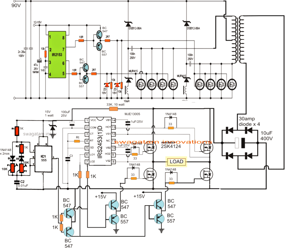
The SD pin of IC IRS2153 is mistakenly shown connected with Ct, please be sure to connect it with the ground line.
Suggestion: the IRS2153 stage could be easily replaced with IC 4047 stage, in case the IRS2153 seems difficult to obtain.
As we can see in the above PWM based 5kva Inverter circuit, the design is exactly similar to our earlier original 5kva inverter circuit, except the indicated PWM buffer feed stage with the low side mosfets of the H-bridge driver stage.
The PWM feed insertion could be acquired through any standard PWM generator circuit using IC 555 or by using transistorized astable multivibrator.
For more accurate PWM replication, one can also opt for a Bubba oscilator PWM generator for sourcing the PWM with the above shown 5kva sinewave inverter design.
The construction procedures for the above design is not different to the original design, the only difference being the integration of the BC547/BC557 BJT buffer stages with the low side mosfets of the full bridge IC stage and the PWM feed into it.
Another Compact Design
A little inspection proves that actually the upper stage does not need to be so complex.
The 310V DC generator circuit could be build using any other alternate oscillator based circuit. An example design is shown below where a half bridge IC IR2155 is employed as the oscillator in a push pull manner.
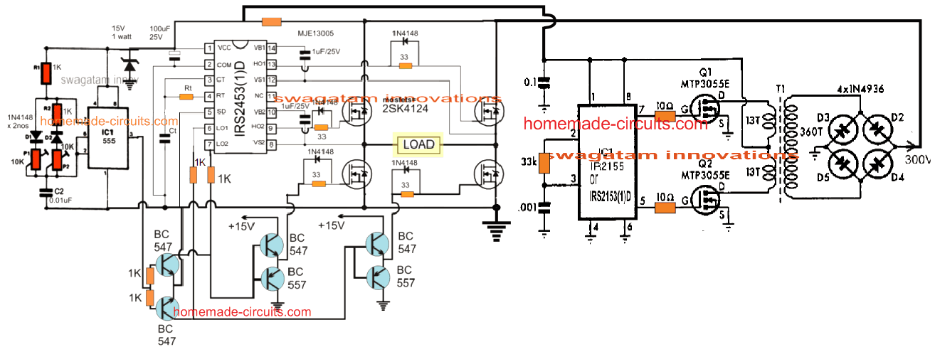
Again, there's no specific design that may be necessary for the 310V generator stage, you can try any other alternative as per your preference, some common examples being, IC 4047, IC 555, TL494, LM567 etc.
Inductor Details for the above 310V to 220V Ferrite Transformer
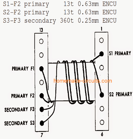
Simplified Design
In the above designs so far we have discussed a rather complex transformerless inverter which involved two elaborate steps for getting the final AC mains output. In these steps the battery DC is first needed to be transformed into a 310 V DC through a ferrite core inverter, and then the 310 VDC has to be switched back to 220 V RMS through a 50 Hz full bridge network.
As suggested by one of the avid readers in the comment section (Mr. Ankur), the two-step process is an overkill and is simply not required. Instead, the ferrite core section can itself be modified suitably for getting the required 220 V AC sine wave, and the full bridge MOSFET section can eb eliminated.
The following image shows a simple set up for executing the above explained technique:
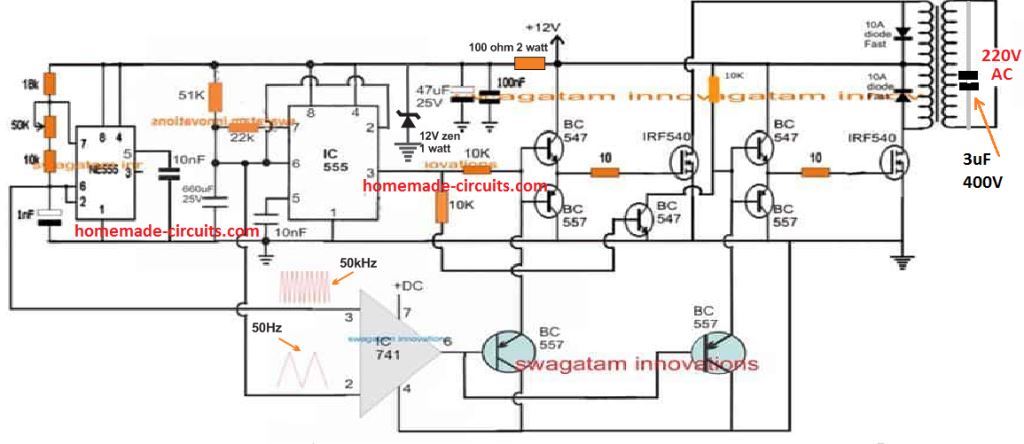
In the above design, the right side IC 555 is wired to generate a 50 Hz basic oscillatory signals for the MOSFET switching. We can also see an op amp stage, in which this signal is extracted from the ICs RC timing network in the form of 50 Hz triangle waves and fed to one of its inputs to compare the signal with a fast triangle wave signals from another IC 555 astable circuit. This fast triangle waves can have a frequency of anywhere between 50 kHz to 100 kHz.
The op amp compares the two signals to generate a sine wave equivalent modulated SPWM frequency. This modulated SPWM is fed to the bases of the driver BJTs for switching the MOSFETs at 50 kHz SPWM rate, modulated at 50 Hz.
The MOSFEts in turn, switch the attached ferrite core transformer with the same SPWM modulated frequency to generate the intended pure sinewave output at the secondary of the transformer.
Due to the high frequency switching, this sine wave may be full of unwanted harmonics, which is filtered and smoothed through a 3 uF/400 V capacitor to obtain a reasonably clean AC sine wave output with the desired wattage, depending on the transformer and the battery power specs.
The right side IC 555 which generates the 50 Hz carrier signals can be replaced by any other favorable oscillator IC such as IC 4047 etc
Ferrite Core Inverter Design using Transistor Astable Circuit
The following concept shows how a simple ferrite cored inverter could be built using a couple of ordinary transistor based astable circuit, and a ferrite transformer.
This idea was requested by a few of the dedicated followers of this blog, namely Mr. Rashid, Mr, Sandeep and also by a few more readers.
Circuit Concept
Initially I could not figure out the theory behind these compact inverters which completely eliminated the bulky iron core transformers.
However after some thinking it seems I have succeeded in discovering the very simple principle associated with the functioning of such inverters.
Lately the Chinese compact type inverters have become pretty famous just because of their compact and sleek sizes which make them outstandingly light weight and yet hugely efficient with their power output specs.
Initially I thought the concept to be unfeasible, because according to me the use of tiny ferrite transformers for low frequency inverter application appeared highly impossible.
Inverters for domestic use requires 50/60 Hz and for implementing ferrite transformer we would require very high frequencies, so the idea looked highly complicated.
After some thinking I was amazed and happy to discover a simple idea for implementing the design. Its all about converting the battery voltage to 220 or 120 mains voltage at very high frequency, and switching the output to 50/60 HZ using an push-pull mosfet stage.
How it Works
Looking at the figure we can simply witness and figure out the whole idea. Here the battery voltage is first converted to high frequency PWM pulses.
These pulses are dumped into a step up ferrite transformer having the required appropriate rating. The pulses are applied using a mosfet so that the battery current can be utilized optimally.
The ferrite transformer steps up the voltage to 220V at it output. However since this voltage has a frequency of around 60 to 100kHz, cannot be directly used for operating the domestic appliances and therefore needs further processing.
In the next step this voltage is rectified, filtered and converted to 220V DC. This high voltage DC is finally switched to 50 Hz frequency so that it may be used for operating the household appliances.
Kindly note that though the circuit has been exclusively designed by me, it hasn't been tested practically, make it at your own risk and on;y if you have sufficient confidence over the given explanations.
Circuit Diagram
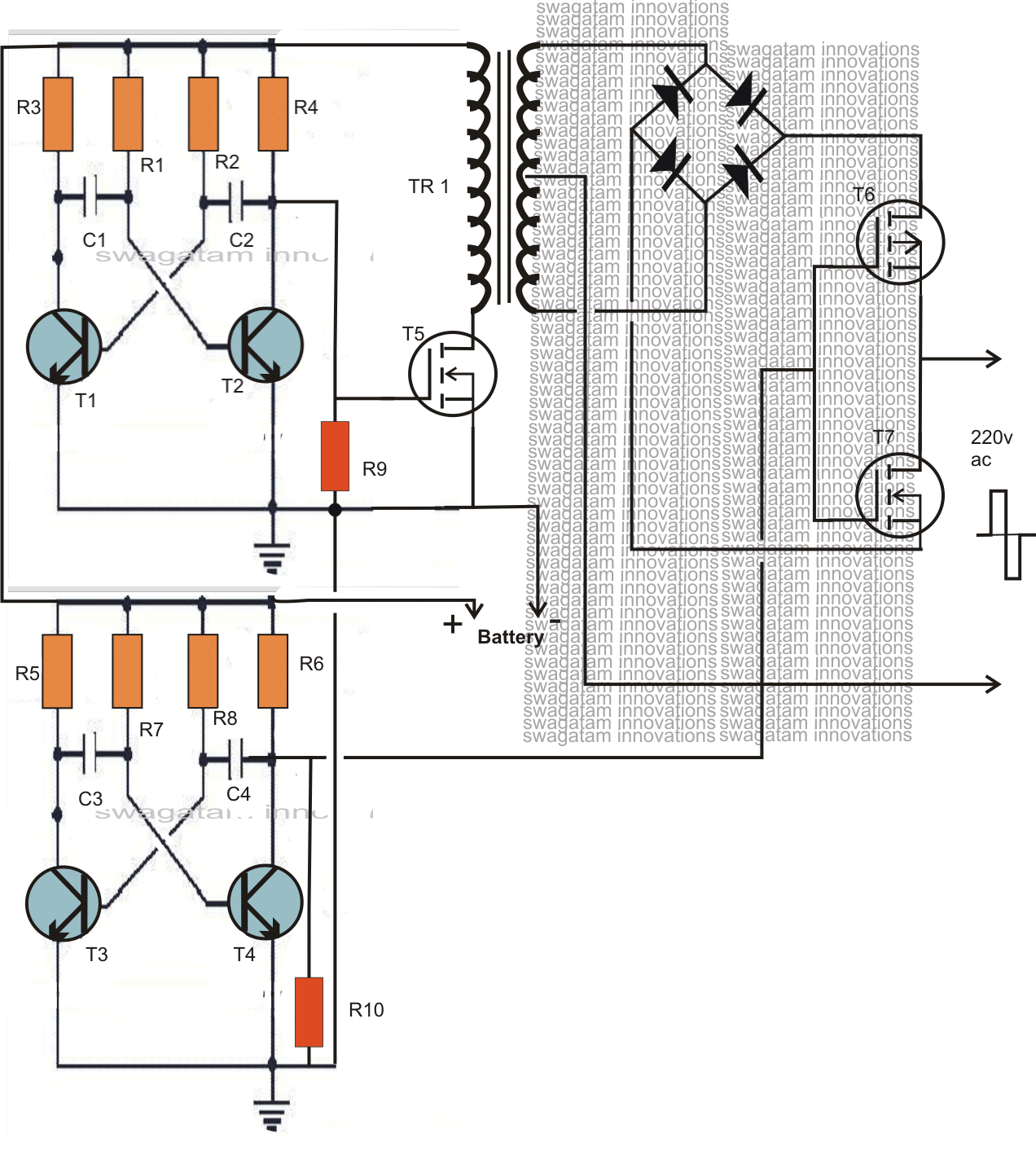
Parts List for 12V DC to 220V AC compact ferrite core inverter circuit.
- R3---R6 = 470 Ohms
- R9, R10 = 10K,
- R1,R2,C1,C2 = calculate to generate 100kHz freq.
- R7,R8 = 27K
- C3, C4 = 0.47uF
- T1----T4 = BC547,
- T5 = any 30V 20Amp N-channel mosfet,
- T6, T7 = any, 400V, 3 amp mosfet.
- Diodes = fast recovery, high speed type.
- TR1 = primary, 13V, 10amp, secondary = 250-0-250, 3amp. E-core ferrite transformer....ask an expert winder and transformer designer for help.
An improved version of the above design is shown below. The output stage here is optimized for better response and more power.
Improved Version
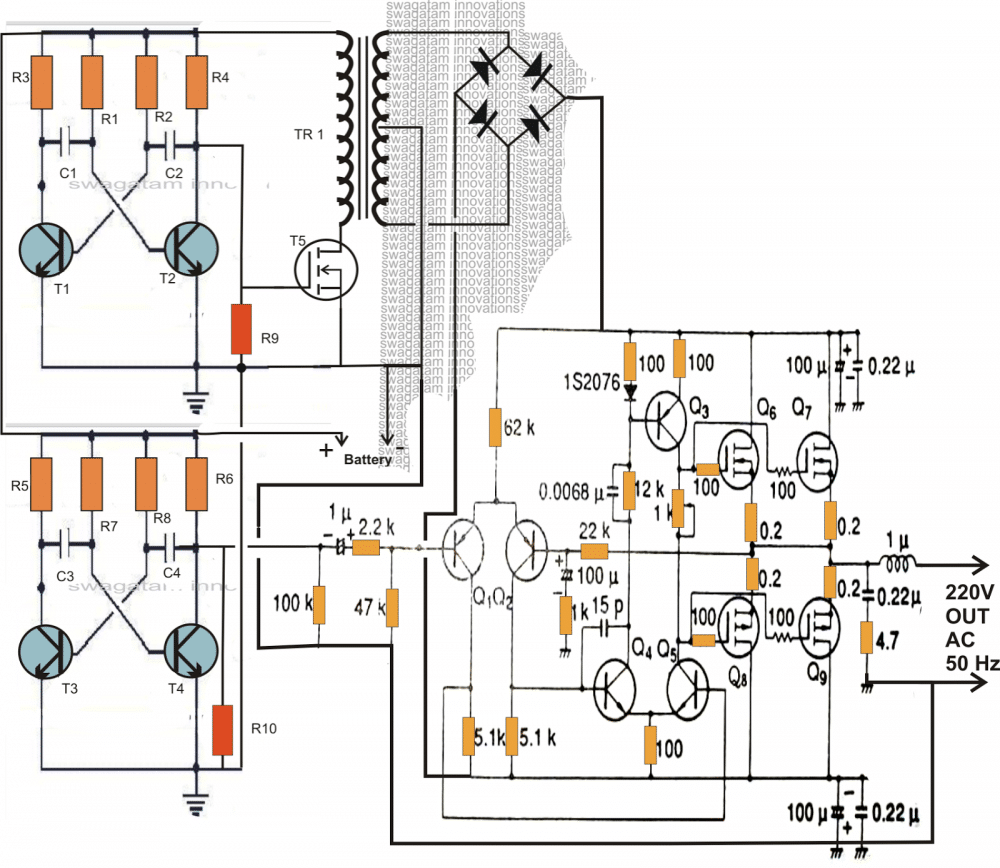




Questions & Answers
Pls…. is dis circuit tested and trusted. Has Dhrubajyoti Biswas
Already tested it to work? Thanks
yes it is a tested design, but the ferrite transformer will need to be designed correctly.
Alternatively a 5kva iron core transformer could be used with primary 50-0-50/100amps and secondary 220V or 120V
Ok… But please am really interested in the ferrite transformer design because of its efficiency and light weight.
you can try it as per the given instructions.
But d concept is different, in d link homemadecircuitsandschematics.blogspot.com/2012/09/making-200-watt-compact-pwm-inverter.html?m=1 high and low frequencies were used, but d configuration in dis 5kva transformer is just like a normal iron core Transformer(no high frequency).
please check the article, now it includes the low frequency stage also….
Good day Sir.
Is it possible for me to have a detailed list of materials for the inverter.
Thanks and best regards.
Radley
Good day Radley,
Please click the diagram to enlarge it, all the numbers are appropriately labelled beside the individual parts, you can easily note it from there.
Good day Sir.
I would like to ask your help again if this circuit is applicable also to 24V input voltage. cause i already have a 24V/220V transformer.
Thanks and best regards,
Radley
Good day Radley,
yes a 24V transformer/battery could be used in the above design, but make sure the IC gets a 12V regulated supply only
Good day Sir.
Is it possible to connect the IC to the battery which is 12 Vdc. Since, I'll be using 4 pcs of 12V. 2pcs connected in series and then connected in parallel with the other 2.
Thanks and best regards,
Radley
Good day Radley, yes that would do, but use the battery which has its negative connected with the circuit negative.
Hello again Sir,
My transformer is 24V-0V. without center tap.
is it still possible for me to use the above circuit.
Thanks and best regards,
Radley
Good day Sir,
Do you other design about a 5kva inverter that has a transformer without center tap.
Thanks and best regards,
Radley
You can try the second circuit separately for your application. Ignore the first circuit.
Connect the mosfet common drains/sources with +/-24V, and connect the transformer primary across the points shown as "load"
Good day to you Sir Swagatam,
Would like to ask you about the symbol load in the diagram.
Does it mean the consumer side already?
Thanks and best regrads,
Radley
Good day Radley, load indicates the appliance you would be interested to operate from the inverter….it's the final output from the inverter which could be used for operating the intended gadgets and appliances.
Good day Sir Swagatam. Hope you're feeling great today. could i ask you for some expert's advice? Which is better to use a Pure sine wave or the pulse width modulation invereter? And also, do you a PWM design which has a capacity of 5kva?
Thanks and best regards,
Radley
Hi Radley, both the counterparts are good, but PWM based are cheaper and more efficient.
Presently I do not have a 5kva PwM based design, if I find one will let you know.
Dear Sir Swagatam,
Thank you very much for the information.
More power to you and may you always be in good health.
Best regards,
Radley
Thanks Radley! It's my pleasure!
Good day Sir, what about the construction of the charging section in the circuit diagram?
Good day Muhammed, I have many battery charger circuit posted in this blog, any one of them can be suitably used with the above circuit for the required operations.
hi sir it been a while thank for the good circuit im interesting in this circuit but there is one thing do not understand and it will be difficult to get it,the two circuit should connect together or it separate? can you please give me any equivalent type of the ic irs2453? or can i replace it with sg3525,TL494?
hi daniel, IRS2453 is a specially designed high side H-bridge driver IC, it cannot be replaced with 3535 or 494 ICs…it can be replaced with another full bridge high side driver only
the output voltage from the first circuit becomes the supply voltage for the H-bridge of the second circuit
ok sir,please sir in the first circuit there is diodes can you please tell me any common diode can 1n4148 or any value of zinner diodes? these are the diods MUR415,DSEM2-06.any replacement of it?
please Google and find the datasheets of the indicated diodes…then check at what voltage and current these are specified…once you know this you would be able to identify and determine a suitable equivalent for the same…..1N4148 will not do.
ok sir thank you ,has this circuit tested?
sir this circuit need another 60v dc? sir please can i ir2110 in place of the two ics? thank you
Not yet tested but I am sure the design is 100% correct technically and will work if built correctly…
yes ir2110 will do..
ok sir i want to ask you again if yes if2110 can replace the two circuit wha t can i do or nothing will going to change? 2110 and irs2453 and ir2153 are they the same pins?
please check the datasheet of the IC, yes the pinouts will be almost the same, but better to confirm from the datasheet
can i use 60v 7ah battery for this circuit? can it power the inverter and make it function well? i am asking this question because i want to connect 12v 7ah in series. Thanks waiting for reply
yes 60V 7AH will work and will provide around 120 watts of power….
Dear sawagatam
second circuit what is CT and RT value please explain
Tks
chandana
Dear Chandana,
It decides the frequency of the inverter, you can select it appropriately for fixing 50Hz at the output
is it possible to get 3000-6000 watt transformers for inverters, like 12v or 24v- 100v ac, because I can never find transformers like that.
no not possible, these will need to be made-to-order
I realize the ready made inverters dont carry big transformers not even for something like a 3000 watt, is there anyway I could do a transformer setup to give me powerful wattage of 3000watts and above without getting custom made transformers?
what you are referring to are inverters using ferrite core transformers, exactly similar to the one discussed in the above article.
Hello Swagatam , you recommended IRF3205 to be use at the output of the H bridge stage that has rail voltage of 310v. Can that mosfet handle such high a voltage.?
Hello Tonyben, IRF3205 will not work since it's rated to handle only upto 55V….instead IRF840 would be more suitable for the mosfet bridge network circuit
I have done the required correction in the article, thanks…
Hello Swagatam, thanks for the good work you doing.
Can i have your email? i want to discuss a design idea with you to see what input you could make to it.
Thanks Tonyben, my email ID is admin@162.240.8.81
I would think so, I think those transformers normally have some yellow plastic covering the coil windings, so if I wish to achieve those results are you saying I would have to use ferrite core transformers?
yes all battery operated compact inverters rely on ferrite transformer, there's no other option…
Hello Swagatam, did you get my email on the design idea ?
Hello TonyBen, I received an email from Mr.McAnthony Bernard, I believe it was sent by you.
Let me assess the requested design, I'll try to figure out an appropriate circuit diagram for the same and post it for you…soon.
Hello Swagatam, yes i did sent the mail. hope to hear from you soon on that.