The IC 4047 is one of those devices which promises an unlimited range of circuit application solutions. The IC is so versatile that on many occasions it easily outsmarts it's close rival, the IC 555, let's study the datasheet and pinout details of this versatile chip.
Main Datasheet and Specifications:
In-built oscillator with variable frequency option through an external RC network.
Complementary push-pull outputs with a separate active clock output, the clock output is actually an extension of the internal oscillator frequency output.
Duty cycle locked to 50% for precision, fail proof operation of the external stages.
The IC 4047 can be configured as a free running astable MV, and also as a monostable MV.
In the astable mode the chip provides the option of integrating external triggering inputs, also called true gating and complement gating modes.
The monostable mode enables positive edge triggering as well as negative edge triggering of the IC.
It further allows retriggerable feature for extending the output timing to the desired calculated level. Meaning after the normal trigger is applied to the IC, more number subsequent triggers can be applied so that the output adds up the timing, generating further delay at the output.
Internal Logic Diagram
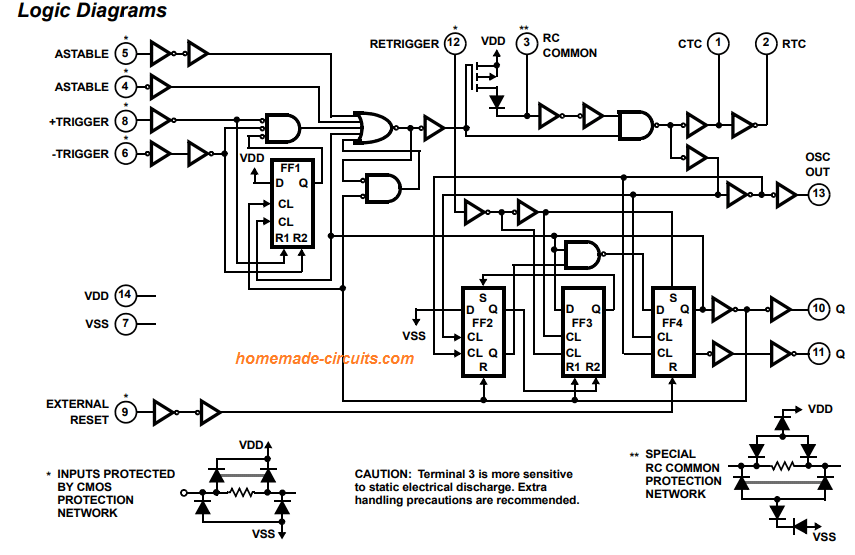
Pinout Details
The following explanation suggests how the pinouts of the IC 4047 may be configured for implementing the above discussed operating modes:
In the free running astable mode, connect pins 4, 5, 6, 14 to positive or Vdd, connect pins 7, 8, 9, 12 to ground or Vss.
Vdd must be supplied with a recommended 3V to 15V and maximum 18V (absolute).
In gated astable mode connect pins 4, 6, 14 to positive or Vdd, connect pins 7, 8, 9, 12 to ground or Vss, connect pin 5 to the reset pin of the external trigger IC, while output of the external chip to pin 4 of the IC 4047.
For the above modes, the output may be obtained across pin 10, 11 (push-pull) while clocks at pin 13.
In positive trigger monostable mode, connect pins 4, 14 to positive or Vdd, connect pins 5, 6, 7, 9, 12 to ground or Vss, connect pin 8 to the reset pin of the external trigger IC, while output of the external chip to pin 6 of the IC 4047.
For the above modes, the output may be obtained across pin 10, 11.
Fundamental Free Running Astable Mode Circuit Diagram Using IC 4047
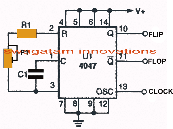
As shown in the figure above, the IC 4047 can be used as a free running astable multivibrator or oscillator by configuring the chip in the above suggested method.
Here R1, P1 and C1 determine the oscillator frequency of the IC and the output at pin10, 11 and 13.
Basically R1, P1 togeter must not be less than 10K, and above 1M, while C1 should not be less than 100pF (higher value have no restrictions) in order to maintain proper functioning of the chip.
Pin 10 and 11 are complementary outputs which behave in a push-pull manner, meaning when pin10 is high pin11 is low and vice versa.
Pin 13 is the clock output of the IC 4047, each high pulse measured at this output enables pin10/11 to change positions with their logic levels, while low logics does not influence any response on pin10/11.
Pin13 is normally kept open when not in use, it may be applied in cases where a frequency or pulsed output may be required for the other stages of the circuit for enhancing purposes, such as for making modified PWM based inverters etc.
Features
- Low-power CMOS design
- Wide operating voltage range: 3V to 15V
- Very few external components required
- Monostable and astable operation modes
- Adjustable pulse and frequency output
- Schmitt trigger input for noise immunity
- Power-on reset
- Pin-compatible with the 4047B
Electrical Characteristics
The following table summarizes the electrical characteristics of the IC 4047:
| Parameter | Condition | Min | Typ | Max | Unit |
|---|---|---|---|---|---|
| Supply Voltage | 3 | 5 | 15 | V | |
| Supply Current | VDD = 5V, No Load | - | 10 | 20 | μA |
| Input Voltage | -0.5 | - | VDD+0.5 | V | |
| Output Voltage | IOH = -0.4mA, VOL = 0.4V | - | - | 0.1 | V |
| Rise Time | CL = 15pF | - | 50 | 100 | ns |
| Fall Time | CL = 15pF | - | 50 | 100 | ns |
| Propagation Delay | - | 100 | 200 | ns | |
| Trigger Voltage | 1.5 | 2 | VDD-2.5 | V | |
| Threshold Voltage | 2.5 | 3 | VDD-1.5 | V | |
| Timing Error | Cext = 0.01μF, TA = 25°C | - | 2 | 5 | % |
| Output Duty Cycle | Monostable Operation, Cext = 0.01μF | 50 | - | 50 | % |
Note: This datasheet provides typical values unless otherwise specified.
Applications
The IC 4047 is commonly used in the following applications:
- Timing circuits
- Oscillator circuits
- Pulse generators
- Frequency dividers
- Switching power supplies
Packaging
The IC 4047 is available in a 14-pin DIP package.
Ordering Information
To order the IC 4047, specify the part number followed by the package type. For example: 4047AN (DIP package).
Making a Power Inverter using IC 4047
The IC is best suited for all types of inverter, converter, SMPS and timer applications.
One typical simple square wave inverter application using the IC 4047 can be witnessed below:
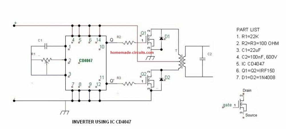
The formula for calculating the frequency or the RC components are:
- In Astable Mode →
tA = 4.4 × R × C
F = 1 / (4.4 × R × C) - In Monostable Mode →
tM = 2.48 × R × C
And this is from the official TI datasheet.



Questions & Answers
Obrigado, Deus abençoe sempre a sua vida.
You are welcome Célio.
hello Ing…delighted with the page,,great and EXCELLENT,,,10 points with your usual help, I ask about the CD4047 for 220Vac 50Hz inverter 1..I
can measure the frequency with a multimeter, that is to say a multitester.
2..In which pin should I measure the frequency to adjust.
Thank you Felix,
Yes you can measure and confirm the output frequency of the IC 4047 using a multimeter having frequency reading capability.
You will have to attach the black probe with the ground line of the IC and attach the red probe with either pin#10 or pin#11. Connect the red probe once on each of these pinouts to check the frequency, they should be exactly equal.
Dear sir,
what is the frequency at pin 10,11. Is it 50 Hz. But sir 50Hz can’t be obtain from the given equation 1/8.8RC. Please help me sir.
Hi Hasai, Pin#13 frequency will be two times that of pin#10 and pin#11. If you wish to have 50 Hz frequency on pin#10, and 11 then pin#13 frequency will be 100 Hz.
In the equation you must convert the capacitor value to Farad. Did you use Farad for the capacitor?
yes sir. I calculated it as below.
f = 1/8.8RC at pin#10 and pin#11
= 1 / 8.8 * ((100+10)*10^3 ohm) * (0.1*10^-6 farad)
= 10.33 Hz
It gives 10.33 Hz. Can you please tell how should we take 50 Hz.
Hi Hasai, I am not able to verify your calculations due to lack of time, however you can easily bring the results to 50 Hz, either by decreasing the value of the capacitor or by decreasing the value of the resistor, or both. You can keep experimenting with lower values until you arrive at the 50 Hz value.
Sir please what is the waveform of pin 2 and 3
I am not sure about pin2, but pin3 will produce triangular waves
Please sir can u help design a pure sign wave inverter using Sg3534/35 with chopped output similar to sign wave.
Hello Moses, a few of those circuits are already present in this website
Can you please tell whether this circuit can be used to supply a tube amp B+? It consumes 100mA.Will a square wave inverter work in tube amplifiers?
Also,using a IRF510 MOSFET? what will be the maximum power output from a 12-0-12,3A transformer?
Square wave AC could produce a buzzing noise at the output of any amplifier, so according to me it cannot be used.
Sir, I’m not an electrician of any kind, but I’m a fast learner. I live out in the dessert off grid and have no electric or running water. I’ve built a wind turbine and with my solar panels charge my 12 volt batteries. Now I need an inverter. Could you recommend some reading that would most quickly givee the knowledge to know how to make one. Thank you.
Signed no more utility bills
Adrian, there are some inverter designing information explained in the following article, which you can refer to for understanding the basic inverter working concept
https://www.homemade-circuits.com/how-to-design-inverter-basic-circuit/
I admire your patience on answering all these comments . may God bless you and your work
swagatam sir,
I have to design a inverter 1KW sine wave will you please suggest how to calculate required MOSFET, IC and resistors and capacitors for required frequency and also for protection and charging circuit
?
Hi Vaibhav,
the mosfet’s Drain-Source Voltage must be ideally twice the battery voltage and Continuous Drain Current should be at least 1.5 times higher than the transformer current rating.
For the above mentioned designs all resistors will be 1/4 watt 1% rated, and capacitors voltage should be rated twice the battery voltage
Dear swagatam
It seems that definition of drain and source pins of IRF150 is mistake in your diagram. Please correct that.
Thank you dear Fereidoon for notifying, I have changed the diagram now!
can you give the value of resistance and capacitor, so i get frequency between 50hz-60hz
I do not have the exact values you may have to practically check it and fix it….
Can’t we convert square wave to sine wave using resistance and capacitor at the output of pin 10 and 11?
you can but you cannot replicate it at the output of the transformer using the conventional inverter topology
Can you please elaborate
you may be able to feed the sinewave to the base/gate of the power devices but the same will not get interpreted at the output of the trafo, it will just be square wave at the trafo output
if I connect the resistance and capacitor to the transformer output will it work?
yes it will work roughly, and might drop some precious power in the course
What’s the difference between CD 4047 and HEF 4047 B and others mark’s.?
no difference
Thanks for answering.,i have another question what is meaning BP, B etc. behind numbers?
According to me those are not relevant to the ICs main technical specifications, so far whenever I have purchased ICs I have looked into the main number for example in this case only the 4047 is relevant and important rest of the things can be ignored….unless there is a CMOS version, for example (7)555 is the CMOS version of IC 555 and may have some technical differences.
Again thanks for answering, another one are different manufacturers have same dimensions of IC for example I have to replace it on PCB board the dimensions of the hole are same?
you are welcome, the dimensions are always standard and precisely identical for all brands that are assigned with same number and package specs.
Is it possible to get a sine wave output from IC 4047?
not possible
nice work,
Thanks sir ,i make this circuit but i want to more efficiency
Syed,
you can try to enhance it as shown in the following article
https://www.homemade-circuits.com/pure-sine-wave-inverter-circuit-using/
Respected swagatam,
I have made small 200w inverter it’s running good but the one filp out 4047 mosfet is to much heating !
I use 4047 ic for ocillator and mosfet is IRF540 use I doing a tryed to
1)Chang old to new mosfet
2)inter changing of mosfet
3) transformer connection Chang
4)Chang with mosfet gate connection to each other
Hello Kanji, If you have swapped the transformer taps with the two mosfets and still experiencing the same issue then that’s very strange, and that looks impossible.
either the mosfet which is heating up could be faulty, or that particular side winding of the trafo could have issues….if all these parameters are swapped, and still the new arrangement is showing heating issues, then that’s understandable.
now the only option left is to swap the 4047 output pinouts, and also the replace the gate resistors of the mosfets, and check the results.
I have checked the output pins through headphones but I didn’t hear any oscillating sound. I think the oscillation is not working. Can you please tell why this is happening? I have tried 10 or 12 ICs and 14 mosfet so all of them couldn’t be damage
If the IC is configured correctly then it should work, there are only two parts that needs to be connected with the IC for a proper working of the IC….and also there are a few pins which must correctly joined with the supply rails…you can confirm the connections from the datasheet of the IC or from other online sources also and check whether you have connected all of them correctly.
Hi,
Above details give osc output as 1/4.4RC(Tosc = 4.4RC) and Q output as 1/8.8RC (TQ = 8.8RC). But the datasheet says Tosc is 2.2RC and TQ is 4.4RC ( 2*(Ton + Toff)). So how you end up in above equation?
Hi, the data was referred from another website so I can’t suggest much on that, you can solve in both ways and test piratically to see which one gives you the right results.
However if I set my multimeter in AC and check the output of the ic I get 27v. Instead of 12v or 6v. I also checked AC current in the battery there is also showing 27v. I think oscillation is not working and I am getting input = output
set it at DC, not AC…it must show 50% of the supply level across the output pins.