Voltage stabilizer in the range of kVAs are powerful AC voltage stabilizer units specially designed for controlling and stabilizing high voltage fluctuations, for high power electrical equipment.
In this article I have explained an easy to build a 7 stage high wattage in the order of 5000 to 1000 watts stabilizer circuit which can be used for controlling our mains AC line fluctuations and for producing very accurate stabilized voltage outputs for our domestic electrical appliances.
Circuit Operation
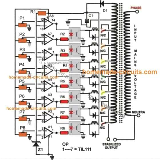
The proposed Accurate 7 relay OpAmp Controlled Mains Voltage Stabilizer Circuit concept is rather very simple. It uses discrete opamps wired up as comparators to sense the voltage levels.
As can be seen in the diagram, each opamp's inverting inputs are provided with sequentially incrementing voltage reference levels through a series of presets which drops a certain amount of voltage across itself.
Each opamp compares this voltage with the common sample mains AC voltage level supplied to the opamps non inverting inputs.
As long as this sample voltage is below the reference level the respective opamps keep their outputs low and the subsequent transistor relay stages remain inactive, however in case the voltage levels tends to shift from its normal range, the relevant relays trigger and toggle the transformer taps so that the output is appropriately equalized and corrected.
For example if the input AC voltage tends to fall, the upper relays may get triggered connecting the relevant higher voltage taps with the output and vice versa in case the voltage shoots upwards.
Here the opamp output inter-connections makes sure that only one optocoupler and therefore only one relay gets activated at a time.
Parts List
- P1---P8 = 10 K Preset,
- A1---A8 = IC 324 (2 Nos)
- R1---R8 = 1 K,
- All diodes = 1N4007,
- All relays = 12 volts, 400 Ohms, SPDT,
- Opto Couplers are all = MCT2E or equivalent,
Transformer = Pink Tap is normal voltage tap, the upper taps are in the decrementing order of 25 Volts, while the lower taps are in the incremental order of 25 volts.
Full circuit diagram of the proposed Accurate 7-Stage OpAmp Controlled Mains Voltage Stabilizer.
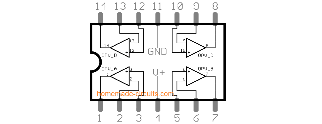
IC LM324 Pinout Details
Circuit Diagram
Upgrading into a Solid State Version using SSR
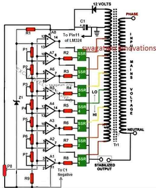
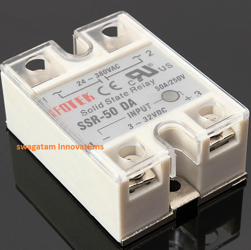
The diagram below shows a rather simple voltage stabilizer design which can hold huge output power in the range of 5 to 10KVA. The use of SSR or solid state relays makes the output stage easy to configure and very accurate - thanks to the modern SSRs which are designed to trigger massive power in response to smaller input DC potentials.
Circuit Description
The proposed circuit of a simple high capacity automatic voltage stabilizer circuit is easy to understand. All the opamps are arranged in standard voltage comparator modes.
The presets P1 to P7 can be adjusted as per the required tripping points, which will correspond to the output SSR switching and the subsequent transformer tap selections.
The central green TAP is the normal voltage output, the lower TAPs gradually produce higher voltages while the upper TAPs are set for lower voltages.
These TAPs are chosen by the appropriate SSRs in response to the varying AC voltages, thus adjusting the output voltage to the appliances close to normal levels.
This circuit was asked by Mr. Alexandar and the SSR data was provided by him.
Parts List
- R1 to R9 = 1K, 1/4 watt,
- R10 = 10k 1/4 watt
- P1 to P8 = 10K preset,
- C1 = 1000uF/25V
- VR1 = 10K Preset,
- opamps = IC 324,
Transformer = Input 230volts or 120volts, Taps - incrementing/decrementing voltage levels (TAPs) as per individual specs.
SSR = 10KVA/230volts = output, 5 to 32 volts DC = input
Full circuit diagram of the proposed A Simple 5 KVA to 10 KVA Automatic Voltage Stabilizer Circuit @220 Volts, 120 Volts
Solid State SSR Voltage Stabilizer Circuit Diagram
SSR Image


Questions & Answers
Sir,
Can you explain igbt based static voltage stabilizer with DSP control popular nowadays.If possible please post a circuit of it.
Nishant, I think I have a similar concept published in this website, you can find it at the end of this post
https://www.homemade-circuits.com/smps-mains-voltage-stabilizer-circuit/
here instead of a transformer I have recommended using large electrolytic capacitor which can add equivalent power to the load during low voltage situations.
hi swag,
what kind of transformer to use?
how many Ampere to meet 5kva – 10kva?
or just only any transformer do well?
thanks..
Hi candra, you will need a transformer which may have a 220V or 120V entry and several outputs producing higher than 220V/120V values in steps, and also lower values than 220V/120V in steps. you will have to contact a professional transformer designer and make to order it or try acquiring readymade from ebay or amazon.
for getting ampere, divide the wattage with the input voltage
ok. thanks
hi swag.please help me with the diagram of electrical series testing board and how to use it.i think it is advisable when testing any short circuit problem.i saw it in youtube but i don’t understand hindi/urdu.thanx
Hi Dennis, for testing an electrical system where a short circuit could be possible, the best technique is to use a lamp in series with the supply. For example you can use a 100 watt series bulb and then freely test the system, if at all a short circuit happens, the bulb will light up preventing any kind of burning or fire hazard issues. This is the most basic idea for safely carrying out a short-circuit prone experiment, if your system is more complex or require a more sophisticated cut off system, then please specify your experiment I’ll try to solve it for you.
ok thanx.i’ll try it first.i want to try it in servicing a tv or any other electronic products.if i have a circuit that i don’t understand,please help me.thanx again.
Sure dennis, let me know if you face any problems.
Hello Dear Swagatam, Please can you guide me on how to setup the two opamps (lm324) for ensuring appropriate shooting/kicking of the relays without crash. Again, at what DC equivalent of 220VAC do I keep the pink (220VAC) tap swiched ON while other stay OFF and vice versa? Please help. Thanks.
Hi Kingsley, you just have to adjust the presets from bottom to the top in an incremental order, such that the lowest relay activates at the lowest voltage threshold, the second lowest at the second lowest threshold and so on until the top preset which activates the topmost relay at the highest voltage threshold..
The lowest threshold could be 150V, and the highest could be 300V.
Thank You very much my dearest electronics mentor! I sincerely do appreciate your effort towards keeping young electronic hobbyists updated. I will try the setup and get back to you with observations.
Thank You once again.
Your are welcome Kingsley, wish you all the best!!
what is the data of Z1 ?
you can use a 6V zener.
thz
Hi my boss swag, this is kaluya moses from Uganda your old student / a follower.
Honestly, thank you for the wonderful job you doing to serve the world electronically God bless you . long live swag.
In fact price of electronic mr swag , I will would like to help me the type of sort ware you use to design or to make schematic diagrams/PBC.
Thank you Kaluya, I am glad you are liking my website! I use Corel-Draw for designing the schematics and PCBs.
Thanks a lot prince of electronics mr Swag, I still need much support from you because i have circuits to design and if at all I need someone to do it for me, what should I do? before I learn to do it myself. please advise me mr Swag. Thanks.
Thanks Kaluya, There are probably many PCB softwares online which you could try, but without learning them it could e difficult. Or you may be you can contact a PCB designer for the job.
Pls can I get a circuit diagram for a 5kva Automatic voltage stabilizer
Assuming a tap is at 170V the next will be at 195v(25v) increment, but the input voltage is at 180v, how will it handle it. Because 180v is in between the taps
Please check and learn how an auto-transformer is designed to work… then try to attach the auto transformer taps into the above circuit accordingly.
please,send transformer data sheets of 5kva and 10kva
Sorry, I don’t have it with at the moment!
Sir swaggatam.
Please I will need your help on a circuit, an AC ADAPTER,19v .3.42A,
Hi Ken,
You can tell me your requirement, if possible I’ll try to help!
Please, advise why pin 4 is of ic1 is not mentioned, IC near to SSR1..?
if we build a 5kv and output voltage is designed 230 v, upon full load, the output voltage will drop to 210v, so how we can keep the output voltage also stable in 230v…?
The position of pin4 is not important in the diagram, it can be seen near the top op amp, pin4 goes to the positive supply
if we build a 5kv and output voltage is designed 230 v, upon full load, the output voltage will drop to 210v, so how we can keep the output voltage also stable in 230v…?
For that you will have to use a transformer that’s rated at 3 times more wattage than the load, in your case use a 12000 watt transformer
Sir,
I am confused between triac and SSR, can you please what is main difference,
I saw a voltage stabilizer cicuit diagram by you using triac. please explain what is the differnce..TKS
Arun, An SSR is a complete module with all the necessary protections built-in…a triac alone may be more vulnerable to damage compared to an SSR.
Happy New 2020, thanks for all your supports Swag. For this circuit, is it possible to use a small transformer of 14v to power the Ic circuit instead of tapping the 14v from the auto transformer. But the auto trafo will be used for the large volt tappings. Thanks
Wish you too a Happy 2020 Adeyemi. Yes that’s definitely possible.
Hi sir, What is the value of C1 and the meaning of P.
Value of C1 can be 1000uF/25V
Thank you for sharing
what is the part number of transfomer..plz send that
i was wondering if you have a 120 volt input and 120 volt output ac circuit stabilizer
Thanks a lot, Mr Swagatam. May God bless you. Please Sir, I want you to show me full video on how to make 1500w including battery charger. Thanks once again.
Thanks Taofeek, I presently do not have the video now but in future if I make one I will surely update it for you….
Hello Swagatam,
great works and thank you for being supportive to students especial on their project works.
I am one of your followers. My question is if you want 1P7S transformer winging coils how do get that from multisim.
Many thanks
Thank you Isaac, sorry I do not know much about it since I do not use simulating softwares very often
Thanks very much for your quick response swagatam. I will be counting on you for your coaching on a project I am currently considering to develop for my research.
God bless you.
Many thanks
Isaac
You are welcome Isaac!
Please provide a circuit for 220VAC and 110VAC stabilizer having an auto transformer with taping of 94V, 109V,127V, 148V, 171V, 199V, 215V, 231V with relays.
You can try the first circuit from the above article and customize the relay contacts as per the tappings of your transformer.
Hi sir.
Please help me with the new generation Stabilizer.
igbt based voltage stabilizer
Hi Amin, I do not have this circuit with me at this moment, but if I find I will post it for you….