Many a times we find it crucial and handy to possess a true three phase signal for evaluating many different electronic configurations such three phase inverters, three phase motors, converters etc.
Since it's not so easy to incorporate single phase to three phase conversion quickly we find this particular implementation difficult to acquire and enforce. The proposed circuit enables the above discussed well calculated spaced and positioned sine waves outputs to be generated from a single master input source.
Circuit Operation
The circuit functioning of the three phase waveform generator circuit may be understood with the help of the following explanation:
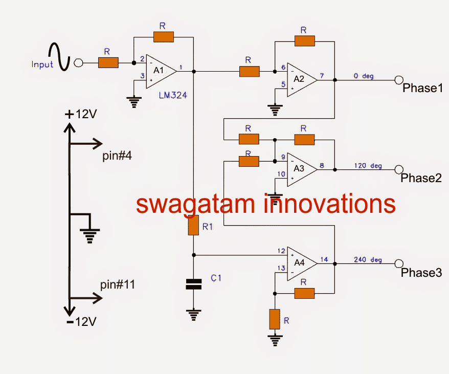
An input sine sample waveform is fed across the point "input" and ground of the circuit.This input signal gets inverted and buffered by the unity gain opamp A1. This inverted and buffered signal acquired at the output of A1 now becomes the new master signal for the forthcoming processing.
The above buffered master signal gets once again inverted and buffered by the next unity gain opamp A2 creating an output with zero degree initial phase across the points "Phase1"
Simultaneously, the master signal from A1 output is phase shifted by 60 degrees via the RC network R1, C1, and fed to the input of A4.
A4 is set up as a non-inverting opamp with a gain of 2 in order to make up for the signal-loss in the RC configuration.
On account of the fact that the master signal is phase shifted 180 degrees from the input signal, and further shifted to an additional 60 degrees by the RC network, the ultimate output waveform gets shifted by 240 degrees, and constitutes the "Phase3" signal.
Now, the next unity gain amp A3 sums up the A1 output (0 degrees) with A4 output (240 degrees), creating a 300 degree phase shifted signal at its pin#9, which is in turn inverted appropriately, shifting the phase to an extra 180 degrees, creating the intended 120 degree phase signal across its output indicated as "Phase2".
The circuit is intentionally wired up to work with a fixed frequency in order to yield better accuracy.
Fixed values are used for R1 and C1 for rendering the intended, accurate 60 degree phase shifts.
For specific customized frequencies, you may use the following formula:
R1 = (√3 x 10^6) / (2π x F x C)
R1 = (1.732 x 10^6) / (6.28 x F x C1)
where:
R1 is in kohms
C1 is in uf
Circuit Diagram
Parts List
All R = 10 kohms
A1---A4 = LM324
Supply = +/- 12vdc
| Frequency (hz) | R1 (kohms) | C1 (nf) |
|---|---|---|
| 1000 | 2.7 | 100 |
| 400 | 6.8 | 100 |
| 60 | 4.7 | 1000 |
| 50 | 5.6 | 1000 |
The above design was investigated by Mr. Abu-Hafss and appropriately corrected for obtaining legitimate responses from the circuit, the following images provide a detailed info regarding the same:
Feedback from Mr. Abu-Hafss:
I needed a 15VAC 3-phase supply to test 3-phase rectifiers. I simulated this circuit the other day but failed to get proper results. Today, I made it work.
IC A2 and resistors connected to pin 6 could be eliminated. The resistor between pin 7 and 9 could be connected between the main input and pin 9. Phase-1 output can be collected from the original AC input. Phase 2 and 3 can be collected as indicated in the circuit.
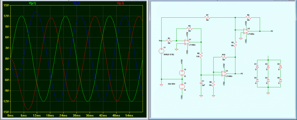
However, my actual requirement could not be fulfilled. When these 3 phases are connected to a 3-phase rectifier, the wave form of phase 2 and 3 gets disturbed. I tried with the original circuit, in that case all three phases gets disturbed
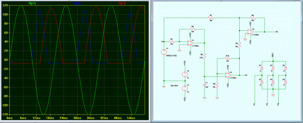
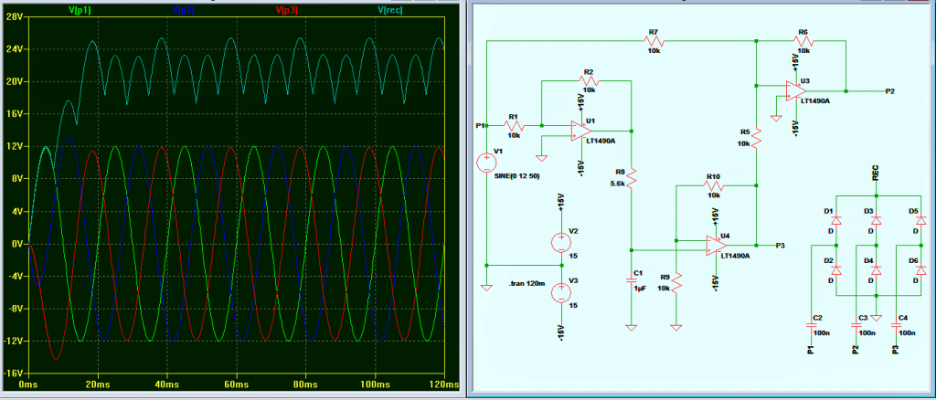
Finally got a solution! A 100nF capacitor connected in series with each phase and the rectifier solved the problem to a great extent.
Though the rectified output is not consistent but, it is quite acceptable
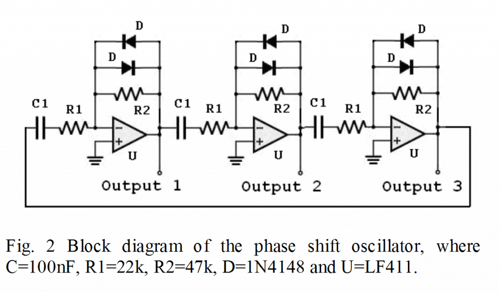
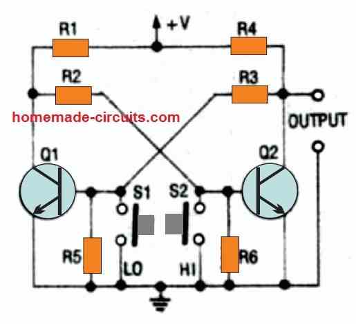
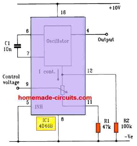
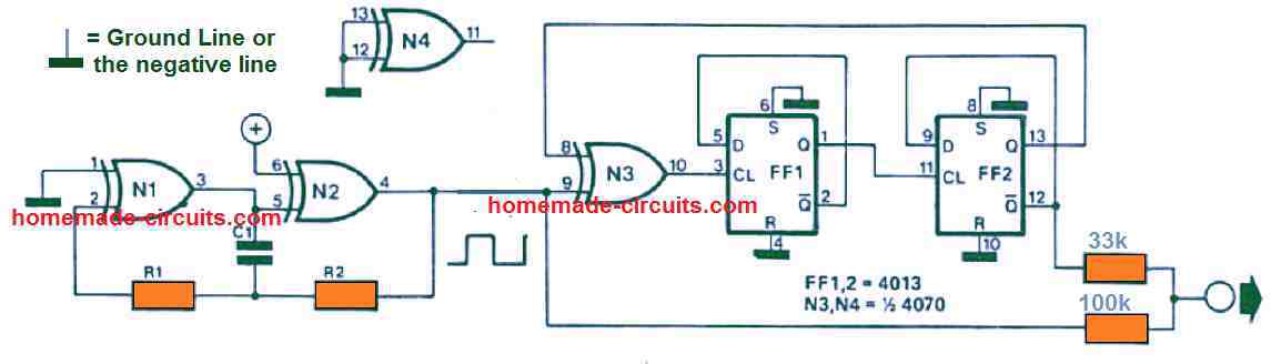
Update: The following image shows a much simpler alternative for generating 3 phase signals with accuracy and without complicated adjustments:

Questions & Answers
You are really helping . sir, Is it possible to convert car alternator to dc motor without PIC? if yes, I need your help on the circuitry. thank you
Thanks Musa, it is possible but it could be a mechanical concept, not within my expertise.
Thank you for the quick reply. I am a proud member of this blog. I can not wait to see the day passing without me visiting this site. I will try the mechanical concept, for the convertion of a car alternator to dc motor. Thank you once again.
You are welcome Musa, I appreciate your interest.
hi sir good day. I'm here again. i have a 3 phase genset(standby generator} i think it was rated 1.5-2kw 440v. My problem is i only need is 1 phase 220v output for my needs can you help me design a circuit to make it 1 phase output. Thank you for your effort of doing this.
Hi Edalcore,
I am sorry I don't any verified approach to do this, so it might be dangerous to suggest something which hasn't been confirmed by me.
Dear edalcor zuproc!
It is possible but only by using a transformer, if your generator has DELTA output, you would require a Delta-Wye Connection three phase transformer with a common neutral on its output to use it for single phase.. (Verified Method)
You may ask for its calculations if you want to design it..!
Hello Swagatam Majumdar…!
I need your kind help please, can you please provide me a frequency converter circuit to convert 220V 50 Hz to 220V 60 Hz for a load of about 5A at 220V using oscillations or any other method using MOSFETS or IGBT's…. please help me regarding this…!!!
plz plz
Hello Muhammad Junaid,
VFD is a very complex circuit, so I don't think it would be possible for me, I'll try though, if I succeed then will surely post it for you.
..a single phase VFD looks slightly easier, I'll try to do it…let's be hopeful
220V 50 Hz to 220V 60 Hz i would say just make from 220 AC –220 DC and after make half bridge mosfet or igbt pulsing on 60 Hz
use 3 phase rectifier and after let it pulsing on halfbridge mosfet or igbt
yes that could be tried….
ok thanks you for you reply.
In your case there are 3 solutions one described by Mohammad junaid.
2nd is to to 3 phase a.c. supply to d.c. supply then again converting it to single phase a.c. supply from d.c. but it is costly.
3rd on is by replaceing old 3phse alternor with new one single phase alternator.
may be 2nd solution is more costly by 1st or 3rd solution.
but before thinking about implemention on any suggesion i advise you to download and read information about preinstalled 3 phase alternator may by its output winding is
star ( Y ) conneted then there is a nutral or common terminal in its connection box.
Hi swatgatam Majumdar you are doing good job and i like your work it is very helpful for bigners or students
Thank you Azam Ali.
Thank you very much sir,
Now just how do we connect these three outputs transistors (MOSFETs) and then to a transformer to realize a usable three phase 380V phase to phase that can be used to power motors?
You will need the following circuits to implement it:
https://www.homemade-circuits.com/2013/10/three-phase-inverter-circuit.html
sir i had one doubt hw did u say the value of R=10Kohms
yes
sir i would like to ask you one question??
i have made a three phase detection circuit in which if the supply goes from RYB TO RBY the circuit detects and gives signal to the relay
but i have one doubt
how should i connect the three phase supply as an input to the circuit
i can not connect directly
i have to create a signal of it
so how will i make that signal which is beyond my knowledge
i can mail you my circuit through gmail
my id is harshal.sharma055@gmail.com
please help me
Hi Harshal, it's a bit tricky, I do not know the correct way of doing it, if i figure it out I'll inform you regarding it.
u have added me in google + so i can mail u the circuit of three phase detection circuit u can then help me out will it work or not …
yes, you can.
hey gud morning swagatam , i have made the three pulse generator , now its shown a single phase source as an input ,from where ill get this single phase source directly from the supply ??
if yes , i did that the the 1st resistor burn out
please help me
in the above circuit what will be the input source i mean what rating
i used it with the230V SINGLE PHASE SUPPLY
and the circuit burn out
Hi Harshal, since the circuit is 12V operated, the input should also be stepped down to 12V AC signal. You can do it by connecting a 0.1uF/400V capacitor in series with the input 10k resistor.
THe outputs will then require half driver circuits to convert the relevant small signal phase shifts into 220V 3-phase AC.
hi swagatam , i m sharing a link from the google drive of the three phase detection circuit
related to that i need ur help
in tat circuit 3 phase input is needed
so i m making a three phase signal using a three phase generator
butwill it work>///?????
link is
https://drive.google.com/file/d/0B7f8SlTe2xORci1SbjMzcGN0LXM/edit?usp=sharing
Hi Harshal,
Make the above circuit and confirm whether you are getting the 120 degrees phase shifts or not by applying a 12V sine AC at the input…..once it's confirmed you can use it with this circuit for the detection.
you will need an oscilloscope for confirming this.
i want to knoe more about this driver circuit is it an inverter circuit??
please refer to the last diagram given in the following link:
https://www.homemade-circuits.com/2013/10/three-phase-inverter-circuit.html
Sir,
How do we generate -12V to connect to pin # 11. And I suppose all the numbers indicated on A1–A4 is the pin numbers of the respective IC.
Jagan, you will need a dual power supply for that, you can easily make a dual power supply by using a center tap transformer or by using a resistive network with a 24V single supply.
Yes those indicate the IC pin numbers.
Jagan ull need to make a dual supply using a centered tapped transformer of 220/15 -0-15 V AND USING 7912 IC u can get -12 volt supply
hi swagatam, i m really thankful to you coz of ur quick response to me
one last question i need to know the use of 0.1 microfarad 400v capacitor y to use it with the input?? is it necessary ??after using this capacitor should i hav to step down the voltage or i can directly connect the input to the supply
Hi Harshal,
with a 0.1uF cap in series you can provide the supply from the mains directly, however it would be rather better to eliminate the capacitor and provide the input from a 0-12V transformer, this would kepp the circuit isolated and ensure safety from mains lethal voltages
Hey swagatam. I want to use this circuit for ac induction motor, please tell me if this circuit is working well. Also I want to know if anyone has build this circuit, thanks and please reply sooners
Emeka, you cannot use the above circuit directly with motor, you will have to employ a three phase driver circuit with it for operating the motor, please refer to the last circuit given in the following link:
https://www.homemade-circuits.com/2013/10/three-phase-inverter-circuit.html
hi swagatam, i made the above circuit, its not working
i m not getting a sinusoidal pulse as an output
also when i measure the voltage across capacitor with multimeter i m getting voltage of 12 v but its d.c. not a.c so now what to do??
Hi harshal,
you will need an oscilloscope to confirm the outputs, there's no other method of confirming an AC sine output with 120 degree phase shifts.
i checked it swagat. but i m not getting a pure sine output also when i m measuring it with the multimeter the output i m getting voltages for both d.c .and a.c
i saw harmonics in the output so couldnt measure the phase sequence
please help me
also the resistance value decreased from 10 K to 8.5 K
so should i change the resistances???
n how to give ground to that single phase source ??
do u have whatsapp messenger so that i can directly be in your contact this will also ease my time as my project dead time is last of april month
???my mobile no. is +918460285967
harshal sharma
In the meter it will only show RMS values, 12V in AC range and 6V in DC range.
Actually the above circuit is not my design and I have not tested it practically, so it will be difficult for me to troubleshoot the circuit correctly.
sorry I do not have a whatsapp account.
what response did you get in the scope? Check the phase shift angle only, that's important…
also i have shared a link previous a circuit of 3 phase phase detection circuit
wich has 10v zener diode , so shold i change it to 5v zener diode???
I haven't yet studied the circuit yet, if you can tell the role of the zener in the circuit then I can suggest whether it needs a change or not
I need a 3 phase pure sine signal
as an input for the three phase detection circuit
also try to study my phase detection circuit
it wil just take a matter of minutes
4 u
also the output of the above circuit is non sinusoidal
but i need threephase pure sine
what kind of waveform are you seeing in the oscilloscope, across the three outputs of the above circuit??
i m trying to make a project which includes the controlling of elevator for 3 floor building, undervoltage and over voltage protection circuit and the three phase detection and protection circuit, well i hav made the controlling and o.v and u.v protection circuit but i am now stuck on this three phase detection and correction circuit??
I'll try to find some other circuit which can create artificial 3-phase signals that you can use for confirming with your detector stage.
the simplest method would be to take a small 3-phase motor and rotate it by coupling it to another motor (by belt or pulley)…once it starts rotating a three phase AC could be achieved across the three wires of the motor.
the zener diodes r just to clip odd the above unwanted waveform and make the sine wave lyk a square wave so it can be taken as a clock pulse
hi swagatam, please i want to know if i can drive a three phase washing machine motor with your Three Phase Inverter Circuit and also i want the motor to run at 8000-12000 RPM
Hi Collins, yes it can be used for the motor but I am not sure regarding the RPM factor.
If I input a square wave with 30Hz, then after passing this circuit become 3 phase square wave? and will the frequency 30Hz changed???
yes it will be converted to a 3-phase square wave with 30Hz frequency
I checked d circuit 0 and 240 are fine but I'm not getting 120 properly on cro.
I think drs prob in à3
240V?? The input sine wave sample should not exceed the IC supply voltage which is 12V here….
hey.. is this possible convert 3 phase to 5vdc without transformer… and by using opamp..
if yes please share …
I have a pcb which convert 3 phase into 5vdc but i am weak in reverse engineering.. could you suggest me the simple way for tracing..
you can try this circuit:
4.bp.blogspot.com/-MR2QAcISl4I/U9z3BuwZ6KI/AAAAAAAAHyw/e1IE6kxm8VA/s1600/3+phase+to+DC.png
connect a 5V adapter such as a cell phone charger across the points "load" for getting the required 5V out
R1 = (1.732 x 10⁶) / (6.28 x F x C1). Hello sir. Thanks for very useful info. From the formula, may i know what are 1.732, 106 and 6.28 represent for?
It was not explained in the original article, so not sure about them
ω = 2πƒ = 1.732/RC as (tan 60 = 1.732)
R1 = (1.732 x 10^6) / (6.28 x F x C1)
the unit of c1 is in nf
the phase shift equation for rc circuit:
Phase shift = arctan (2πfRC)
Will u pls post or mail the original article link
Hi Swagtam
I needed a 15VAC 3-phase supply to test 3-phase rectifiers. I simulated this circuit the other day but failed to get proper results. Today, I made it work.
IC A2 and resistors connected to pin 6 could be eliminated. The resistor between pin 7 and 9 could be connected between the main input and pin 9. Phase-1 output can be collected from the original AC input. Phase 2 and 3 can be collected as indicated in the circuit.
However, my actual requirement could not be fulfilled. When these 3 phases are connected to a 3-phase rectifier, the wave form of phase 2 and 3 gets disturbed. I tried with the original circuit, in that case all three phases gets disturbed 🙁
Any suggestions??
Just got a solution! A 100nF capacitor connected in series with each phase and the rectifier solved the problem to great extend.
Though the rectified output is not consistent but, it is quite acceptable.
Thank you Abu-Hafss,
That's very impressive and this will be quite handy for all the readers out there who may be trying to build the above circuit successfully.
I'll update the corrected images in the above article soon
Thanks for uploading my findings.
However, this line
"Though the rectified output is not consistent but, it is quite acceptable."
should be mentioned at the end.
Hi Genius,
I want a circuit that can convert single phase AC( 220v 15 amps 50-60 hz) to three phase 120 deg phase shift ( 440 v phase to phase 50-60 hz) that can run a 3hp induction motor.
I am an Automation engg. from Mech. background and I have been looking for this circuit from a long time. it happens in VFD but they are too costly for the product that we are planning. Will really appreciate your help in it.
Thanks Debu,
I have already published a few related circuits in this website, you can refer to those in the below given links, if you have problems understanding the concepts you can feel free to interact with me:
https://www.homemade-circuits.com/2014/12/3-phase-vfd-circuit.html
https://www.homemade-circuits.com/2013/10/three-phase-inverter-circuit.html
sir good day…sir have you design a much simple circuit for a single phase to three phase system…
you can refer to the following article:
https://www.homemade-circuits.com/2014/12/3-phase-signal-generator-using.html
Dear Majumdar,
what is the input value of the ac in the above circuit..? and how much will be the out put ac?
Actually i need 3 phase 24 or 12V ac at60Hz out put. and i have 12 and 24 v ac 60Hz.
Dear Basheer,
the output will be equal to the peak to peak value of the IC supply voltage, if the supply is 12-0-12V then the output will be also in accordance with this value,
The input could also be equal to this value but not above this to avoid voltage clipping.
Hie swagatam plz can you help me build a three dc to ac inverter 48/240
Hi Adonis, I already have a 48V inverter circuit in this blog, do you want 3 separate inverters or tied up together.
the request
sir,need pwm coding for three phase multilevel inverter @Swagatam Majumdar
sorry Basit, I have no idea about it….
Hello Mr. Majumdar, I would like to ask you how did you get the 60 degrees phase shift to sum up with the 240 degrees from A4? thanks for your time
Hello Rich This design is not mine, rather taken from another source, I have not yet investigated the calculations so far, so can't comment regrading it..
Oh ok, hehe. I have to check then. The thing is that I used this network for my work. Works fine and I understand all the process except that part I asked you.
Thanks anyway for your time.
thanks for updating your experience!
Can I use Motor of 3-Phase Motor 2 HP with above sequence . ?
yes you can
Hi Swagatam,
Can the variable frequency signal [ from 1 to 60 Hz] circuit from timer 555 to feeds into its controlled board to run a salvage 3phase induction washer motor from 120VAC ?
Hi Cong, if you change the frequency in IC 555, it will also proportionately vary its PWM, it's better to use IC 4060 for getting a variable and perfect 50% duty cycle frequency…but the output will be a square wave which might not suit your induction motor
what software simulator you used to show the graph ?
Hi Amir
The software is LT Spice IV, it free to download at http://www.linear.com/designtools/software/
Hello. for the updated circuit, could you tell me what the resistance and capacitance is to make the 50 Hz frequency? And how to change the frequency with the resistance?
Hello, I assume that it is originally calculated for 50Hz, nonetheless you can practically test it and tweak the results if required by changing the R or C values accordingly…
Hi,
We have connected the circuit as given in picture3 as done by Mr. Abu-Hafss.
The output for 120degree is not coming , it is only 60degree phase shift. for obtaining 120 degree phase shift i had to connect one more RC circuit at the output of U3. please help with this.
Please explain the working of the summer used.
Also, what is the value (1.732*106) is the equation, R1 = (1.732 x 10⁶) / (6.28 x F x C1)
Thank you in Advance.
Chaithra
Hi, This circuit was referred from another article long ago and not designed by me, therefore regarding the circuit functioning I won’t be able to suggest much.
Regarding the formula, I have updated it in the article with more details. Most of the variables in it are constants.
Congrats for your nice job!
Tell me please if this circuit is capable to drive the module PS21245-E.
You see I have one PCB from an old inverter air condition with built in the above mentioned module and I’d like to convert it to a 3-phase power supply unit.
Thanks in advance
Petros
Thank you, yes you can use it for feeding HIN, LIN inputs of the mentioned 3 phase driver module
Because there are six (6) mosfets into this module and I’m not familiar with these deep waters can you give some more help. Can you tell me which are these Hin & Lin on the following Data sheet.
pdf.datasheetcatalog.com/datasheet/MitsubishiElectricCorporation/mXqtqy.pdf
Thanks for your time
Petros
Please look for these pinouts of the IC
HIN = High-side input (PWM)
LIN = Low-side Input (PWM)
Good your publication, your project gave me an idea to convert from a single-phase network system to a three-phase system but without OPAMPs, only with transformers and electronically controlled, it is phase shift and module according to the load variation of the electric motor… thanks… greetings