If you are looking for an option to replace conventional welding transformer, the welding inverter is the best choice. Welding inverter is handy and runs on DC current. The current control is maintained through potentiometer.
By: Dhrubajyoti Biswas
Using Two Switch Topology
When developing a welding inverter, I applied forward inverter with two switches topology. Here the input line voltage traverses through the EMI filter further smoothing with big capacity.
However, as the switch-on current pulse tends to be high there needs the presence of softstart circuit. As the switching is ON and the primary filter capacitors charges via resistors, the power is further zeroed by turning the switching ON the relay.
The moment the power is switched, the IGBT transistors gets used and are further applied through TR2 forward gate drive transformer followed by shaping the circuit with the help of IC 7812 regulators.
Using IC UC3844 for PWM Control
The control circuit used in this scenario is UC3844, which is very much similar to UC3842 with pulse-width limit to 50% and working frequency to 42 kHz.
The control circuit draws the power from an auxiliary supply of 17V. Due to high currents, the current feedback uses Tr3 transformer.
The voltage of 4R7/2W sensing register is more or less equal to the current output. The output current can be further controlled by P1 potentiometer. Its function is to measure the feedback’s threshold point and the threshold voltage of pin 3 of UC3844 stands at 1V.
One important aspect of power semiconductor is that it needs cooling and most of the heat generated is pushed out in output diodes.
The upper diode which consists of 2x DSEI60-06A should have the capacity to handle the current at an average of 50A and loss till 80W.
The lower diode i.e. STTH200L06TV1 also should the average current of 100A and loss till 120W. On the other hand, the total max loss of the secondary rectifier is 140W. The L1 output choke is further connected with the negative rail.
This is a good scenario since the heat sink is barred from hi-frequency voltage. Another option is to use FES16JT or MUR1560 diodes.
However, it is important to consider that the max current flow of the lower diode is twice the current to that of the upper diode.
Calculating IGBT Loss
As a matter of fact, calculating IGBT’s loss is a complex procedure since besides conductive losses switching loss is another factor too.
Also each transistor loses around 50W. The rectifier bridge also loses power till 30W and it is placed on the same heat sink as IGBT along with UG5JT reset diode.
There is also the option to replace UG5JT with FES16JT or MUR1560. The loss of power of the reset diodes is also dependent upon the way Tr1 is constructed, albeit the loss is lesser compared to the loss of power from IGBT. The rectifier bridge also accounts to power loss of around 30W.
Furthermore when preparing the system it is important to remember to scale the maximum loading factor of the welding inverter. Based upon the measurement, you can then be ready to select the correct size of the winding gauge, heat sink etc.
Another good option is to add a fan as this will keep a check on the heat.
Circuit Diagram
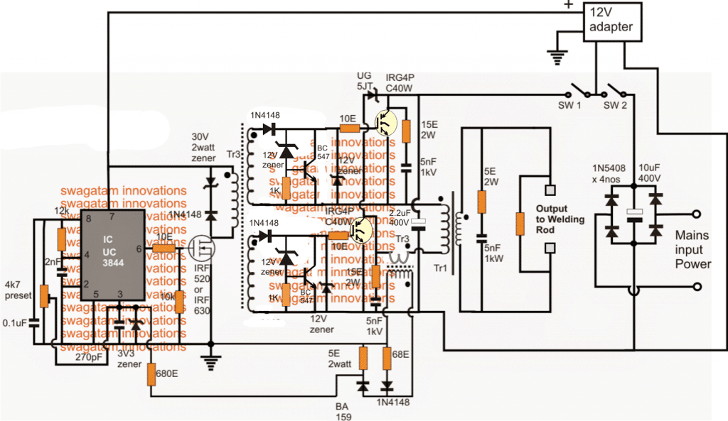
Transformer Winding Details
The Tr1 switching transformer is wounded two ferrite EE core and they both have the central column section of 16x20mm.
Therefore, the total cross section calculates to 16x40mm. Care should be taken to leave no air gap in the in the core area.
A good option would be to use 20 turns primary winding by wounding it with 14 wires of 0.5mm diameter.
The secondary winding on the other hand has six copper strip of 36x0.55mm. The forward drive transformer Tr2, which is designed on low stray inductance, follows trifillar winding procedure with three twisted insulated wire of 0.3 mm diameter and the windings of 14 turns.
The core section is made of H22 with the middle column diameter of 16mm and leaving no gaps.
The current transformer Tr3 is made of EMI suppression chokes. While the primary has only 1 turn, the secondary is wounded with 75 turns of 0.4 mm wire.
One important issue is to keep the polarity of the windings. While L1 has ferrite EE core, the middle column has the cross section of 16x20mm having 11 turns of copper strip of 36x0.5mm.
Furthermore, the total air gap and the magnetic circuit are set to 10mm and its inductance is 12uH cca.
The voltage feedback does not really hamper the welding, but it surely affects the consumption and the loss of heat when in idle mode. The use of voltage feedback is quite important because of high voltage of around 1000V.
Moreover, the PWM controller is operating at max duty cycle, which increases the power consumption rate and also the heating components.
The 310V DC could be extracted from the grid mains 220V after rectification via a bridge network and filtration through a couple of 10uF/400V electrolytic capacitors.
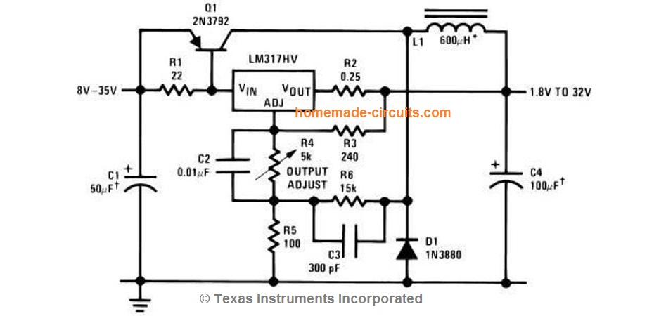
The 12V supply could be obtained from a ready-made 12V adapter unit or built at home with the help of the info provided here:
Aluminum Welding Circuit
This request was submitted to me by one of the dedicated readers of this blog Mr. Jose. Here are the details of the requirement:
My welding machine Fronius-TP1400 is fully functional and I have no interest in changing its configuration. This machine that has an age is the first generation of inverter machines.
It is a basic device for welding with coated electrode (MMA welding) or tungsten arc gas (TIG welding). A switch allows the choice.
This device only provides DC current, this is very appropriate for a large number of metals to be welded.
There are a few metals such as aluminum that due to its rapid corrosion in contact with the environment, it is necessary to use pulsating AC current (square wave 100 to 300 Hz) this facilitates the elimination of corrosion in cycles with inverted polarity and turn the melting in the direct polarity cycles.
There is a belief that aluminum does not oxidize, but it is incorrect, what happens is that at the zero moment that it receives contact with air, a thin layer of oxidization is produced, and which from then on preserves it from next subsequent oxidization. This thin layer complicates the work of welding that's why AC current is used.
My desire is make a device that be connected it betwen the terminals of my DC welding machine and the Torch to obtain that AC current in the Torch.
This is where I have difficulties, at the moment of building that CC to AC converter device. I am fond of electronics but not expert.
So I understand the theory perfectly, I look at the HIP4080 IC or similar datasheet seeing that it is possible to apply it to my project.
But my great difficulty is that I do not do the necessary calculation of the values of the components. Maybe there is some scheme that can be applied or be adapted, I not find it on internet and I do not know where to look, that's why I ask for your help.
The Design
In order ensure that the welding process is able to eliminate the oxidized surface of an aluminum and enforce an effective welding joint, the existing welding rod and the aluminum plate could be integrated with a full bridge driver stage, as shown below:
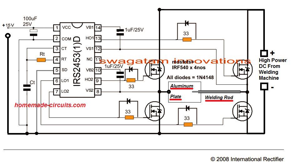
The Rt, Ct could be calculated with some trial and error to get the mosfets oscillating at any frequency between 100 and 500Hz. For the exact formula you could refer to this article.
Th 15V input could be supplied from any 12V or 15V AC to DC adapter unit.




Questions & Answers
Dear,
This Welding Invertor found interesting and I planned to try out. For this I had some queries if you could answer to help me. I was unable to find BC327 transistor in Circuit Diagram which is mentioned in Description. More Elaborate description of Circuit would have been beneficial
Thanks in advance
Actually, the earlier diagram had BC327, which was replaced by me with 7812 ICs for making the design simpler….so you can ignore the BC327 explanation as now it's been replaced with 7812 stage
How many amps were on the mains circuit this was tested on and will it work on 120 without modifications?
Dear Swagatam,
Thanks for Reply , this clarified me of BC327 , Further analysis of the Circuit created some more doubts
that is weather Tr3 is there for High Voltage Protection in Idle More or Over Current Protection When Welding Electrode getting Short Circuited and Tr1 Core getting Saturated at such high Currents
This doubt is due to separate transformer Tr3 used for feed back which is mainly monitors the current in primary winding of Tr1
I feel above both Kind of protection required , hope our discussion will shed some light over this
Thanks
ananda vernekar
Dear Anand,
TR3 is s current sensing transformer, meaning it will activate during overload or short circuit conditions for safeguarding the IGBTs.
TR3 is also supposed to function for high voltage conditions, since a high voltage will force the load to consume excessive current, triggering TR3 into action.
Swagatam I am looking for a switching type power supply that can deliver at least 10amps (prefer 15 to 20amps). The output voltage needs to be at least 100VDC (prefer 115-125VDC). In the past I have built linear supplies but they are very heavy and extensive. This does not need to be highly regulated as I am using it for cutting metal. I just need the current and voltage and mains isolation, the isolation is important as persons could easily come in contact with the cutting action. Any possibility you might have a design that would work or could be modified. I have been looking at inverter welder type power supply hence I stumbled across you very fascinating blog. I have no idea what kind of voltage or current your welder may be able to deliver.
Thanks Ben, I think the above circuit is the one that might perfectly suit your application need.
the voltage can be set by adjusting the given 4k7 preset, and the current can be predetermined by appropriately scaling down the wire gauge of TR1 secondary.
another version of the same circuit can be witnessed in the following llnk:
https://www.homemade-circuits.com/2014/07/adjustable-0-100v-50-amp-smps-circuit.html
Dear Swagatam,
Thanks again for reply and which cleared doubts further, now I am ready to start building the circuit.
another guidance required from you regarding I am Having a Medium frequency Torroid of size OD57mm ID28mm Thickness 28mm also its AL value is 2500 as per supplier Can I use this and what precaution should I take
hope you will guide me
initially I had built a inverter which is running well as per circuit using 4047 and irfz 44n from this site , I wanted to thank you for that also
thanks
Ananda
Thanks Ananda, I'll try my best to help you out, however mains operated SmPS circuits can be very unpredictable and tricky, so it's never recommended for the newcomers, even a slightest of a mistake in the inductor winding, or core misalignment can instantly cause a fire or explosion…therefore please be informed regarding these dangers before you begin with this project….
how to change to 200 amperes?
Hi:
very interesting circuit, but at the first look i have the following question. Please do answer them.
1. after the sw1 and sw2 the positive track, before the igbt, goes down and joins the negative—short circuit.
2. I dont see any diodes at the output of Tr1….so does it work as an AC output?
Waiting to hear from you
1. IGBTs are connected in series…the "short" which you are referring to is for completing the IGBT gate negative biasing from the 7812 IC.
the mains AC power actually passes through the two IGBTs and the TR1
TR1 output diode is eliminated for the sake of simplicity…you can add it if you want.
Dear Swagatam. Nice to read your circuits of inverters…
Can you help with idea to build up circuit for inverter of special: input 220v(AC), output Frequency 4Khz, power 10kva,max current 3000DCA.
Jacky, that looks too huge, for me that would be difficult to design
Hi Swagatam. I am looking for circuit of inverter of special: input 220V(AC) output 4kHz, 10 (KVA), max current 3000 (DCA).
If you can help, pls help with circuit
Thanks in FWD
thanks, anyway no matter it can be huge, can you draw its possible circuit on paper. like what kind tranzistors and how many, diodes, condensators, resistors, transformer MGN etc. would be nice of you
Jacky, so say it's 10kVA and 220V, then it cannot be 3000 amps.
10000/220 = 40 amps
so your current requirement should be 40 amps, not 3000 amps which looks unfeasible.
45 amps to be precise!
I see some of your circuits are about 42KHz, mine is 10 times less 4 Ghz.
Actually need it for me to weld 2mm copper wire onto the brass plate of 1mm
If has any other related circuit for it?
Anyway If its huge what about this: input 220v(AC) , 4 Khz, 4 (KVA), 1000DCA. Probably it is also suitable
again that's incorrect parameter
4000/220 gives 18 amps, not 1000 amps
ок
you can try this
https://www.homemade-circuits.com/2016/05/mini-welding-machine-circuit.html
Dear Swagatam can you provide details circuit having i/p 24vac/vdc to 110vac/vdc and output 0-24vdc , 5amp .
Dear Anandbabu, you can try the following concept
https://www.homemade-circuits.com/2013/11/125v-to-120v-mains-adjustable-voltage.html
for 5 amp you may have to use an additional outboard transistor connected across the IC i/p, o/p terminals
Hi Swagatam, I have been approached by a boiler maker doing most of his work in the remote areas that are off-grid, he was wondering if there is a solution he can weld through solar, if he can provide 310VDC on the input from solar will the above circuit work, if so , what modification are required , the man already has 310VD solar panel he is using for pumping water , he may use same when he is not irrigating , thanks in advance, again I have constructed few of your circuits and are functioning very well , will email PCB layout and final pics for others to use
Thanks Lufono, the 310V DC must also have minimum 10 to 20 amp current for getting good welding joints.
However the above circuit may not be required at all…..a high value capacitor at the output of the solar panel would be enough to allow the welding to happen…the capacitor could be in the order of around 500uF/400V.
Dear Swagatham
Good after noon. Thank you for publishing the smps welding power supply, but i have a small doubt in one of the track short circuiting the positive and negative bus immediately after rectifying the mains supply please clarify. (The same doubt was raised by another person on 23rd Feb 2016 and your answer was not satisfy the doubt properly)
Dear Balakrishnan, yes I think I misunderstood the earlier question, actually there should be a 2.2uF/400V filter capacitor at the center of that line….if possible I'll try to correct it soon..
what was your reason for going igbt over mosfet? Im in the process of building a spot welder, shit ton of parts sitting in front of me…as well as building a high speed drill press with a 1400w hobby rc motor with shaft swapped to collet shank 8mm er11…
im going to need a large psu for that motor. ive got maxwell dcell caps 6 in series 2p strings and balncing bits for the spot welder… being able to charge those up real quick wouldnt hurt either.
also ive always wanted a tig or mig setup in the future so it sort of seems the perfect time to build something like a 200a 220v/240v with say 4-24v dc adjustable output
somewhat new to stuff EEs do but I also just finished a smart bms layout so ive got 2 rather challanging projects under my belt design wise (the ESC was cheap on ebay so i didnt bother for dp)
from what ive read mosfets surpassed igbts in almost all areas a year or 2 ago but im not saying i understand every aspect. just looking for some reasoning to help me grow here
welcome to my site john, To be frank this is not my design, it was inspired from another source.
However as far as I know, IGBTs are better equipped compared to mosfets, due to two basic reasons.
1) IGBT’s gate triggering is neither voltage controlled nor current controlled, simply put a IGBT can be triggered using minimal voltage levels, and with negligible current, whereas mosfets cannot be efficiently triggered below 8V.
2) The second feature of an IGBT is its extremely low conduction path across its collector/emitter, much lower than a mosfet can provide, this resistance becomes crucial when huge current is involved, in which again IGBTs beat mosfets easily…:)
Hey dear friend Swagatam. Your efforts are absolutely remarkable. I learnt alot from your blog and i always pray for your success. Here i need a little help from you as there is no other like you who can help me with this.
I liked your version of smps welding inverter. I actually want to use mosfets in a welding inverter. My plan is as follows:
Mains 220v–>Rectifier–>Mosfet Oscillator driven by sg3525 or ir2153 etc–>Ferrite Transformer–> Rectifier—> welding output. (Only one ferrite transformer, it would be easy for me to experiment)
As i know less about smps so i’m confused. Can you help me with an example of schematic or (roughtly drawn schematic on paper would also be helpful) thanks…
(Will always love your posts, thanks for being great)
Regards
Edeson
Hi Edeson, you can try the following design and modify the transformer with higher rated wire gauge, and see if it works as per your requirement
https://www.homemade-circuits.com/smps-2-x-50v-350w-circuit-for-audio/
I believe it would work. I need to make little modification. Thanks for giving me this brightest idea. You’re amazing man. Hats off..!
Good day Sir swagatam.
I am one of your followers to your electronic project and circuit and I know that this is the right place to ask regarding for the trouble of my inverter welding machine. I have a 200a inverter welding and one day I discovered that my machine is breakdown after used of my friend.
The trouble of my machine is the igbt 1mbh50d-060s in 4 pcs in this parts is blown and after I replaced the parts but same happened in blowing of same part. Can you please help me for this problem. Thank you
Thank you R.Bon.
An IGBT is like a switch, it will burn or break only when the current through it has exceeded its maximum tolerable spec, which might happen due to a short circuit or an overload conditions. The welding machine may have a high frequency circuit, if this high frequency generation stops oscillating may also result in blowing off the devices….so I think the driver oscillator section of the machine may be malfunctioning, and blowing the devices, or another reason may be the tank circuit which is responsible for generating the high power output could be damaged, most probably it’s the driver circuit which may be faulty
Thanks R. Bon, yes that’s right, the IGBT mentioned by you could be driven by an oscillator, and this must be in turn switching a ferrite cored transformer. If the driver oscillator malfunctions or if there’s some kind of short circuit anywhere in the transformer, the devices will keep blowing.
Thank you so much Sir, this is another chance to practice and learn and that is why I can’t throw this machine because I believe that they have an person like you that can’t stop to help to other. Thank you again Sir. By the way, the circuit diagram of my machine is already attached and sent to your email. guesting and pointing the component to check are appreciated.
Hi R. Bon, sorry, I could not find any emails from you!
Good day Sir Swagatam,
Sorry sir, wrong email address. Sir, can you please quide me to insert the circuit diagram here in this forum just to continuemy topic in regarding to the fault of my inverter welding machine.
Thank you again sir.
Hello Sir Swagatam, I mean point of possible fault components to check sir because I don’t hav3 an idea were can I start to trace the fàult parts. By the way Sir Swagatam, the schematic diagrams is already attached to your email that you give. Thank you for your help!
Hello R. Bon, still cannot see any email, not even in the spam folder, alternatively you can upload it on any free online image hosting site and provide the link here.
Ola amigo tem muitos projetos interessantes em seu site sou grato pela ajuda, poderia me passar a indutância do TR2? pois fiz com 14 voltas trifilar em um núcleo toroidal, porem esta consumindo uma corrente acima do normal e com isso aquece o CI e deforma a onda, medi esta em volta de 200uH.
I am sorry friend, I don’t know the inductance value of the transformers. Try adding one more turn and check the response. This design was contributed by another author, so I don’t know all the details.
Hii sir swagatam. Im interest with your answer on the conversation about inverter mma weld, may i question abaout mma welder…? About frequency /square out / voltage and amp . If i have mind want to modif mma weld arc to tig can it set up and what kind it schema and then were it’s the schema put on…? Sorry sir if my english write is bad im on learn and i appreciate your answer
Hi Andi, which schematic are you referring to, is the last one? The frequency details are given at the bottom of the article. The voltage and amp can be as pr the welding capacity, it will need to be calculated by some trial and error method.
Thanks sir for reply, i want to know the position input and output pwm on mma weld arc 200amp. Couse i would like to modife it with volt and frequency rangge , can it be
sorry, I do not have this information at this moment!